What is a reed switch
A reed switch is a type of relay. The word "reed switch" is an abbreviation for the words "sealed contact". This is the main feature of this electronic device.
Sealed contact
Conventional electromagnetic relays have movable and fixed metal contacts. There is an air gap between them. When they close or open, an electric arc is formed. The air between the contacts acts as a conductor. Arcing damages the contacts and shortens the life of the relay.
A reed switch works in a similar way, but the terminals are in an inert gas environment. For this reason, arc ignition is not possible. Consequently, the reed relay contacts do not burn out, which increases the service life of the electronic device.
Part device
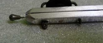
The reed switch sensor looks like a small glass tube made of green translucent glass. There are wire leads on both sides. They allow you to solder the part to the board or connect wires to it. There are also three-pin models.
Inside the glass tube there is a cavity with an airless environment. The cavity contains contacts that are connected to the terminals of the device located outside. This part does not have semiconductors. Therefore, it can operate on alternating current.
Reed switches are quite varied in size. Small models have a length of 10-15 mm. The larger ones are the size of a palm.
This is interesting! There is a tendency to reduce the overall dimensions of reed switches. In 2022, the American company put into mass production a part with a tube length of 4.01 mm. In 2005, the Japanese also had achievements in this area and announced the production of a prototype with a flask length of 2 mm. However, these details have not yet received wide distribution.
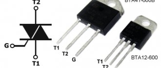
Types of contacts
Reed switches have a classification similar to other types of relays. In terms of contact status, the following models exist:
- With normally closed contacts. If you bring a magnet close, the device's terminals open.
- With normally open contacts. If you bring a magnet close, the terminals will close.
- With changeover contacts. If the magnet is nearby, one group of terminals is closed. If the magnet is removed, the first group will open, but the second will close.
According to the contact arrangement, reed switches are divided into 2 types:
- With dry contacts. Made of solid metal.
- With wetted contacts. There is a drop of mercury inside. It reduces the contact resistance of the device and eliminates contact bounce.
From the point of view of the internal environment, there are 2 types of devices:
- Inside the tube is an inert gas (usually nitrogen).
- A vacuum environment is created inside. This reed switch is used in high voltage circuits, including 220 volts and above.
Vacuum reed switch with mercury
Operating principle of a reed switch
The contacts are activated under the influence of a magnetic field. Its source is usually a permanent or controlled electric magnet.
The field from the magnet easily penetrates through the glass into the sealed cavity. Once inside, it interacts with the metal contacts of the device.
The magnetic field sets them in motion, thereby closing or opening the electrical circuit connected to the terminals of the part. Therefore, to check the functionality of such a relay, it is enough to bring any magnet to it.
Operating principle of a reed sensor
Closing and opening contacts requires some magnetization time. It is measured in units of milliseconds, so in practice it is usually not taken into account. In most cases, it is acceptable to assume that the reed switch is triggered immediately when it enters a magnetic field.
Water level sensor assembly
- Attach the Reed switches to the plastic clamp with hot glue, having previously determined the required distance experimentally. Treat the connection with silicone;
- Place the finished bracelet on the coupling. The length of the float holder determines the actuation stroke of the device;
- The float must be heated with a hairdryer and quickly placed on the coupling, then glued and connected with rivets. The clamp should rotate easily around the coupling with reed switches;
- Install the plugs on the float and attach it to the profile with rivets;
- A neodymium magnet is also attached, which should be within the operating distance of the reed switches;
- Drill a hole in the coupling and install the float stopper;
- Place the assembled structure on the pipe and connect the plug and LED indicator.
I am attaching photos of the assembly:
How to operate a reed switch
Reed switches close (open) contacts when exposed to a magnetic field. The field source is usually a permanent or electric magnet.
If we are talking about a permanent magnet, then the reed switch is in a closed state when the magnet is nearby. If you move it to the side by 5-7 mm, the contacts of the device will open.
With an electric magnet, you don't need to move anything. The reed switch tube is located inside the electromagnet coil. When voltage is applied to it, a magnetic field is generated. It keeps the terminals closed. If the voltage is removed from the electromagnet, the field will disappear and the terminals will open.
Electromagnetic switch with reed switch
How to Choose Professional Technical Services for Reed Switch Connection
It will not be difficult to implement the connection of a reed switch with your own hands, having the abilities and knowledge in this area. If you lack the competence to connect the sensor with your own hands, then it is better to turn to the services of professional services that will carry out the connection cheaply and very quickly.
To select such services using the Yudu service, you need:
- Write a statement on the resource or call the indicated contact numbers
- Set the desired price for the service
- Find the offer that suits you best
- Get acquainted with reliable reviews about the work of performers
- Contact the selected service and arrange a visit
Advantages and disadvantages
Like any electronic components, reed switches have advantages and disadvantages. Advantages:
- increased wear resistance;
- compact overall dimensions relative to conventional relays;
- absence of intrinsic noise and signal distortion;
- contacts are isolated from environmental dust.
- inability to work in conditions of extraneous magnetic fields;
- spontaneous opening and sticking of contacts at high currents;
- fragility, vibration intolerance;
- increased contact bounce due to their elasticity.
Explanation of markings
On electrical circuit diagrams, the reed switch is designated as a circle with normally open or normally closed contacts. The symbol resembles an ordinary button surrounded by a circle.
In the technical documentation, the reed switch is marked with letters and numbers. For the designations of most such devices, the following is true:
- 1st character – name of the part (MK – magnetically controlled contact);
- 2nd symbol – type of contacts (A – normally open, B – normally closed)
- 3rd symbol – the letter “P” is indicated only on devices with mercury;
- 4th character – length of the flask in millimeters (two-digit number);
- 5th character – functional feature of the device (1 – low and medium power, 2 – high power);
- The 6th character is the serial number of the development.
Designation system for reed relays
For example, you can disassemble the MKA-14103 model:
- MK – magnetically controlled contact;
- A – closing;
- the letter “P” is missing, which means without mercury;
- 14 – flask length 14 mm.
- 1 – low or medium power;
- 03 – development order (useless in practice).
Materials for making a water level sensor
- coupling diameter 50 mm, 2 pcs.;
- plug d. 50 mm, 2 pcs.;
- plastic clamps, 2 pcs.;
- plastic furniture profiles;
- heat-shrinkable cambric 30-40 mm;
- plastic plate t. 4-6 mm;
- rivets 10 pcs.;
- neodymium magnet 1 pc.;
- reed switches 3 contacts, 2 pcs.;
- low-voltage button (switch) 1 pc.;
- resistor 680-1.5k. 1 PC.;
- LEDs, 3 pcs.;
- low-voltage wires 5-core;
- plug 4 legs;
- hot glue, silicone;
- power supply 12V, battery 3V.
Tools you will need:
- electric drill;
- heat gun;
- construction hair dryer;
- soldering iron;
- screwdrivers, pliers, etc.
Simple examples of everyday use
The reed switch is a simple part, so radio amateurs willingly assemble various devices on it with their own hands. Below are 3 popular solutions that are implemented using this part:
- Signaling. A secret magnet is attached to the door (it is advisable to use neodymium). A door reed switch is installed on the cladding. It is necessary to fasten it so that when the passage is open, the reed switch terminals are open, and when the passage is closed, they are closed. As a result, the door status is converted into an electrical signal. It can also be converted into an alarm sound.
- Homemade on-board computer for a bicycle. In this case, the magnet is installed on the wheel or drive sprocket of the bicycle. The reed switch is fixed on the frame of the “iron horse”. The higher the speed of the bicycle, the more often the magnet comes into close proximity to the part. Using a microcontroller circuit, these pulses can be converted into the current speed of the bicycle or the distance traveled per day can be calculated.
- Use as a limit switch on moving mechanisms (for example, on automatic gates).
Additional Information! The electronics industry also produces reed switches for security alarms. Such amateur-class devices include the wireless door opening sensor ALD01. Professional systems use mortise reed switches, which do not attract attention. They allow you to hide the fact that the detector is operating.
The operating principle of a reed switch is based on its interaction with a magnetic field. If you bring a magnetized object to the reed switch, its terminals will close. And if you place this part in the field of a controlled electric magnet, you will get a relay with increased wear resistance.
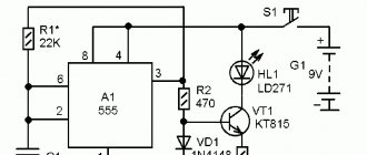
The simplest DIY ANTI-THEFT (two schemes)
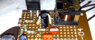
The proposed anti-theft scheme is suitable for protecting against theft of a car, motorcycle or moped. In cars with an installed security system, it can play the role of an additional means against intruders. Its main advantages are simplicity, low cost and reliability. To assemble a circuit with your own hands, you do not need expensive and complex components.
The article describes in simple words all the details, their purpose and operating principle, which will allow even those who have no idea what radio electronics are to understand the topic. In total, two variants of the circuit are offered.
Reed switch for 220 volts alternating voltage
I “invent” a liquid level sensor: a tube inside which has a reed switch and a magnet is put on the tube, which is on foam plastic, for example. The round one is convenient because guides are not needed to maintain the position of the reed switch-magnet axis. The tube can be either HDPE or polypropylene.
I’m preparing for spring so that the drainage wells don’t flood. There is little hope for frogs - they have failed repeatedly, especially when triggering is needed at a low level.
Then it’s especially not worth applying 220 to the reed switch. the ring magnet will be heavy..
But I would advise you to use a system of level gauges without moving parts anyway - if you want, do it yourself, if you want, assemble it from a KIT kit, if you want, buy a ready-made one from the same ARIES:
https://www.owen.ru/catalog/42541599
Liquid level sensors January 13, 2014
In your household, you may need various kinds of water level sensors or other liquids, which you can make with your own skillful hands without much difficulty. I searched the Internet and offer you several options for circuits for various needs related to liquid levels, their monitoring, control, regulation and other things. The circuit options are as follows: LED indication of six liquid levels, automatic pump control and a couple of simple circuits for just sound indication when the container is filled with water.
To turn the pump on and off, it is more convenient to use, in coordination with the control circuit, an actuator relay on an electromagnet. All found circuits use such switching. And this is logical, since electronic keys in the case of engines are less reliable. It is only important to select a relay that matches the parameters of the pump motor, so that later you do not have to look for a replacement if its contacts are damaged.
Six liquid level indicator with light indication
Despite the apparent abundance of wires and elements in the above diagram, in fact, it is ridiculously simple. Since there is only one logical chip among the active elements, the remaining elements are all passive, and the circuit does not require any adjustment at all, since it is “logic” in its purest form. And all the values of the elements of each of the six channels for each logical element are the same, so you just need to connect the input and output of each and repeat this six times. It is further clear: contact 7 is common, and 1-6 are levels, each of them can be placed at the desired height directly in the container for light indication. The LEDs can be arranged in a row (or in another manner), which will indicate the level of liquid in the container being filled: from 1 to 2 pieces light up at the same time. If desired, you can, of course, use LEDs of different colors.