10.09.2021
The circuit diagram for this acoustic switch was found on one of the bourgeois sites. After checking, it became clear that the circuit was not working, after some experiments and alteration of the circuit - lo and behold! she earned it! Almost all the values of the components used were changed to make the circuit more accessible to beginner radio amateurs, and this is the end result.
Perhaps this is the simplest circuit that can exist; it uses a minimum number of components that are available to everyone. As a result of the alteration, domestic parts were used, which greatly facilitates the selection. The microphone was taken from a Chinese tape recorder; you can also use domestic ones, such as pine.
The microphone amplifier is assembled on two KT315 transistors, but to increase the sensitivity of the microphone it is advisable to use transistors like KT368 or its imported analogues; in general, transistors are not critical.
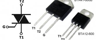
The power part of the circuit is a powerful bipolar transistor that controls the load, and in order to control large loads a relay was used (12-24 or 220 volts).
The signal from the microphone is amplified and sent to the base of a powerful key, the transition opens and it is at this moment that the relay is triggered, the microphone reacts to loud sounds (for example, clap), the sensitivity of such a circuit is 4-5 meters. At the second clap, the circuit is automatically switched off, therefore, the supply of current to the load is stopped.
The capacitors are electrolytic, the voltage is not so important, you can use the appropriate capacitors with a voltage of 10, 16, 25, 50 volts.
The range of supply voltages is also quite wide - from 3.5 to 14 - 16 volts, the current consumption in idle mode (when the circuit is turned off) is practically zero. The circuit can be assembled either on a breadboard or by surface mounting; the values of the parts are not critical and may deviate in one direction or another by 20%, but try not to replace the capacitances of the capacitors used, since the best parameters are obtained with the capacitors indicated on the diagram.
List of radioelements
| Designation | Type | Denomination | Quantity | Note | Shop | My notepad |
| Bipolar transistor | KT315A | 2 | To notepad | |||
| Bipolar transistor | KT818A | 1 | To notepad | |||
| Rectifier diode | 1N4007 | 1 | To notepad | |||
| Electrolytic capacitor | 1 µF | 2 | 10-50V | To notepad | ||
| Resistor | 10 kOhm | 2 | To notepad | |||
| Resistor | 3 MOhm | 1 | To notepad | |||
| Resistor | 48 kOhm | 1 | To notepad | |||
| Resistor | 1.8 kOhm | 1 | To notepad | |||
| Resistor |
set NS048
Based on this acoustic relay, you can independently create security systems, as well as other devices that can respond to sound, for example: automatic sound lighting switches, systems that track the source of sound and, of course, “smart” toys.
Specifications
Supply voltage [V] 9-12
Maximum current consumption [mA] 60
Description of the operation of the acoustic relay
The appearance of the acoustic relay and its electrical circuit are shown in Fig. 1
and
Fig.
2. Fig. 1.
Appearance of the acoustic relay
The electrical circuit consists of two main parts: analog and digital. The analog part includes two operational amplifiers A1 and A2, the digital part includes inverters N1...N4.
From the output of the electret microphone, an electrical audio signal is supplied to the input of the first operational amplifier A1, which matches the microphone with the output stage assembled on the operational amplifier A2. The sensitivity of the circuit as a whole is set by trimming resistor P1. The gain of the output stage is determined by the ratio of resistances R7, P1 and R5.
The amplified audio frequency signal is fed to the driver circuit. As it passes through inverter N1, capacitor C2 is charged to a logical one voltage at the lower input of inverter N2 in the circuit. As soon as the capacitor is charged, the output N2 changes the logical level to the opposite one, thereby forcing the trigger circuit built on the N3N4 inverters to switch to the opposite state. A logical one appears at the output of inverter N4, opening transistor TR1. As a result of this, LED D2 lights up and the winding of the electromagnetic relay K1 is connected to the power source, which switches the load through contacts K 1.1. Diode D1 is necessary to protect the transistor during its switching from current surges resulting from transient processes in the electromagnetic relay winding.
If the electret microphone does not pick up acoustic vibrations for some time, the variable component at the output of operational amplifier A2 will be zero, which leads to the appearance of a logical zero at the output of inverter N1. Capacitor C2 begins to discharge through resistor R1. After the discharge process is terminated, driver N2 resets the trigger circuit to its original state, which leads to the closure of transistor TR1, and consequently, de-energization of the electromagnetic relay winding. The load is switched off. The acoustic relay goes into standby mode.
Acoustic relay assembly
Before assembling the acoustic relay, carefully read the recommendations for installing electronic circuits given at the beginning of this book. This will help avoid damage to the printed circuit board and individual circuit elements. The list of set elements is given in Table. 1.
Table 1.
List of elements of the NS048 set
| Characteristic | Title and/or note | ||
| Brown, green, red* | |||
| R2, R9, Rll, R12 | Yellow, purple, red* | ||
| Brown, grey, orange* | |||
| Brown, black, orange* | |||
| Brown, black, brown* | |||
| Red red, red* | |||
| Orange, white, brown* | |||
| Trimmer resistor | |||
| 100 µF, 16/25 V | Capacitor | ||
| 10 µF, 16/63 V | Capacitor | ||
| Capacitor (22p - marking) | |||
| Capacitor (104 - marking) | |||
| Capacitor (56 - marking) | |||
| Red LED | |||
| Transistor. Replacement BC548 NPN | |||
| 7400 or 74LS00 | Chip | ||
| LF353 or TL082 | Chip | ||
| Electret microphone | |||
| Printed circuit board | |||
| Sockets for microcircuits | |||
| Relay 6V/2A | |||
| Battery connector | |||
| Pin contacts | |||
| * Color coding on resistors. | |||
Form the element leads, install them on the board and solder the leads. Connect the power supply and load according to the diagram shown in Fig. 3.
Rice. 3.
Connection diagram of the power supply and load to the acoustic relay board
Turn on the power to the acoustic relay electronic circuit. Use resistor P1 to set the required sensitivity of the device. Now everything is ready for successful operation of the acoustic relay.
In the event that you want to make a structurally complete device based on the NS048 kit, you can select a suitable stabilized power supply and housing for the acoustic relay in the catalog given in this book or on the website www.masterkit.ru. The design of the board provides for its installation in the case: for this there are mounting holes along the edges of the board for 03 mm screws. A correctly assembled device does not require additional configuration for operation.
Even a novice radio amateur can assemble such an acoustic relay. The NS048 kit is already fully equipped with everything you need, so all that remains is to install the components. Problems that arise during assembly can be discussed at the conference at https://www.masterkit.ru, and questions can be asked at:
NS048 sets, as well as other sets from the MASTER KIT catalog, can be purchased in radio parts stores or at radio markets.
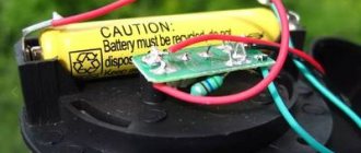
Hello everyone, today we are going to talk about the acoustic switch, and although there are many IC circuit diagrams for this on the Internet for beginners, sometimes it is difficult to find the ICs. With transistors this is already easier and simpler, I saw the diagram - it is surprisingly simple: a two-stage signal amplifier from a microphone on a KT315 or take the modern transistors indicated in the diagram. For example 2sc945 with high gain. You can also replace the power bd140 with the domestic KT818. At first I used 2 pieces of bc547, but later, after testing the circuit with bd140, it turned out that it had burned out, then I replaced it with kt818 and everything worked. The acoustic relay is powered by a 15 V battery. Microphone, taken from a Nokia headset. Transistors bc547 and kt818, load - lamp from garlands, resistors are looking for exactly at nominal value. Capacitors are not a problem. I collected everything on cardboard for the experiment.
The light bulb is designed for 6 volts, so it didn’t last long and burned out after two pops. But it is clear that it works...
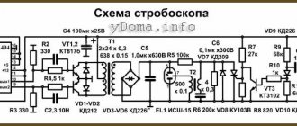
Let's take a look at the diagram. The photo shows the parts we need.
We draw conclusions after the tests - pros and cons.
pros
: the circuit is simple and does not require configuration, scarce parts are not used, simplicity of the circuit, large power range.
Minuses
: the relay reacts to any loud sounds, especially low frequencies. Low sensitivity, unstable operation at sub-zero temperatures, you need two claps, and sometimes three.
As you can see, there were more disadvantages than positive aspects; on the other hand, the design showed itself to be very good, with its simplicity. Good luck to all beginners in their endeavors and good work of electronic devices!
Acoustic switch made easy | DIY master class
A couple of weeks ago, an LED panel for room lighting was assembled and it was decided to assemble an acoustic switch for it, and today I want to look at perhaps the simplest acoustic switch circuit.
The scheme was found on one of the bourgeois sites and slightly altered. The device allows you to turn the power circuit on and off with a clap. I intend to use it to turn on the lights. The device is quite sensitive thanks to a double amplifier using low-power transistors. It responds to clap at a distance of 5 meters from the microphone. All parts were replaced with domestic ones.
The microphone amplifier uses domestic transistors of the KT 315 series with any letter or index. The final stage uses a powerful transistor switch based on a bipolar transistor of the KT 818 series, all other details are the same as in the original circuit. You can exclude the relay from the circuit and connect a load in its place, but this is only in cases where you need to control loads with power up to 12 volts; if you need to control loads with power from the network, you can’t do without a relay. At the moment of clap, the microphone receives the wave, and as a signal it is sent to a power amplifier, which alternately amplify the signal received from the microphone. The amplified signal arrives at the base of the switch, its magnitude is sufficient to trigger the transistor, and at this moment the junction of the transistor opens and conducts a current that powers the connected load or relay.
When assembling, observe all the ratings of the parts; even a slight slope can lead to abnormal operation of the switch. The device responds not only to pops, but also to low-frequency noise (powerful bass, etc.).
The supply voltage range is from 4 to 16 volts, power only from stabilized DC voltage sources and under no circumstances use switching power supplies, the device will not work with them!
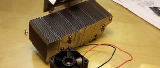
For the trial version, the device was mounted mounted, then it will be transferred to the board, the main thing is that everything works without failures.
sdelaysam-svoimirukami.ru
Principle of operation
This acoustic switch operates on a special microcontroller that allows you to turn off the light by clapping your hands. Of course, such a control device can be used not only to control a lamp, but also many other electrical devices: fans, air conditioners, transformers.
Photo - cotton model EV-01L
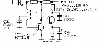
The simplest sound switch consists of an electronic microphone in which a preamplifier is installed. Thanks to this part, any sound that enters the device is amplified several times, due to which even the smallest pops are perceived by the sensitive element. The operation of the amplifier itself is additionally controlled using transistors VT1 and VT2. The circuit is regulated by two resistors R2; rectifying diodes VD1 and VD2 are installed to level the signal.
Photo - diagram
When a clap sounds, the signal passes through the microphone and is amplified, after which it is converted into an electrical impulse. This pulse is equalized by rectifying diodes. The sound at which the light turns on is controlled by a resistor, i.e., if the sound of the clap does not exceed a preset value, the light bulb or other device connected to the switch will not turn on. After leveling the signal on the capacitor (indicated C8 in the diagram), the voltage increases, then the transistor switch VT3 opens.
Turning the light off and on is done by alternately discharging and charging the capacitors. After a full cycle of repeated clapping, the resistor and capacitor C10 will be discharged within 4 seconds, and the device will go into the off state.
SIMPLE ACOUSTIC RELAY
| radioskot.ru An acoustic switch is a very useful and necessary thing in the household, especially if you want to automate some devices or lighting in your home and add creativity to your home! Using an acoustic switch, you can turn the lighting off and on or use it for other devices, such as an electric kettle or fan. This scheme is fully operational, streamlined and stable. There are many diagrams of similar devices on the Internet, but when assembling them, a lot of performance problems arise and some of them lead to long discussions at the end of which, the problem is often not solved. Below is the diagram itself. The circuit is powered by a voltage of 5 to 9 volts, so choosing a power source will not be difficult. You can use, for example, a crown or other batteries and accumulators. If you need stationary power, then there are many power supply circuits online, even a transformerless one will do. The printed circuit board is made for DIP components, but despite this, it has quite compact dimensions and choosing a housing for it will not be difficult. You can download the printed circuit board from the link: akusticheskiy_vyklyuchatel.zip (downloads: 463) List of parts for assemblyPCB manufacturingI will not explain in detail how to make a printed circuit board, as it will take a lot of time. The PCB file is opened using the sprint-layout 6.0 program: sprint-layout-6.zip (downloads: 394) The circuit uses diode VD1; it is needed to protect transistor VT3 from the EMF of the relay coil. If you connect a relay as a load, then you need to install a diode; if you use a light load, then you can install a jumper instead. After making the board, to avoid oxidation, tin the thresholds with tin. Open the sprint-layout 6.0 program and solder all the parts on it according to the location. If everything is done correctly, the parts and values are not mixed up, then the device should work immediately without any problems. This is what the assembled acoustic switch looks like. And one more photo with a connected battery and an LED on the load. I would like to tell you about one problem that may arise. The circuit contains a 1.5 kOhm resistor R8, if you use an LED as a load, you can leave it, if you plan to install a relay, then replace the resistor with a 2 Ohm. There shouldn't be any more problems)) The result was an inexpensive but very effective and useful device that will definitely find its use in the household!)) Source usamodelkina.ru |
Device installation
You can assemble a simple cotton acoustic switch with your own hands; it consists of the following parts:
- Resistors;
- Capacitor C12;
- Diode bridge (say, VD7-VD10);
- Transistors.
Please note that the capacitors must be at least 40 Volts. But not everyone likes to fold electronic devices themselves, so it will be easier to buy a cotton sound switch from the store. There you can choose a model to suit any needs and capabilities.
Photo - assembled cotton controller
The installation of the cotton regulator is carried out according to the classical scheme, in which it is used together with a conventional one-key or two-key regulator. Each individual device has an individual connection diagram, but in principle they are all very similar. In short, you need to connect a single-key model to the network so that it powers the cotton one. How to do it:
- The standard operating diagram of the switch and lamp is as follows: power is supplied from the panel through the distribution box to the standard switch. The neutral from the shield is led to a lamp (or several lamps). The lamps are connected in parallel to the disconnecting device;
- You need to break the power circuit that goes to the key switch and install it on the acoustic one. It's very easy to do. The main advantage of such a device is its small size. There is no need to trench the wall, since such a controller is mainly installed on the lamp body;
- As a standard, the switch has two pairs of wires: white and black. White ones are allocated for power, black ones for load. For example, white ones are connected to the phase and neutral cables from the panel, and black ones are connected to the lamps;
- Individual cords can be connected using special terminals or simple winding. Soldering the fastening points is not recommended;
- After this, you need to turn on the regular key switch and check the operation of the system. If you need to completely remove it from the system, then reinstall the power wires so that they are connected directly to the cotton model.
Photo - arrangement of elements
DIY cotton switch: diagram, video, photo
To increase comfort and simplify everyday routine, people are constantly improving devices and inventing new ones. Today we’ll look at a device for controlling electrical appliances remotely using sound. A homemade cotton machine is useful, for example, for turning on the light in a vestibule or pantry, where for some reason finding the switch in the dark is difficult or inconvenient. Below, for the readers of https://samelectrik.ru, we will tell you in detail how to make a cotton switch with your own hands, what elements need to be prepared and according to what scheme to carry out the assembly.
Assembly diagrams
All cotton or acoustic machines are united by the presence in the circuit of a microphone, which is needed to record sound. The design also provides a trigger or time relay to control the power relay.
In this circuit, operating from a 220V network, the signal from the electret microphone is supplied to transistor VT1 for amplification, then to the resistance matching unit, the emitter follower on transistor VT2. Next, a trigger and a signal comparator are assembled on the TM2 digital chip.
A comparator is necessary to protect the switch from acoustic interference; it cuts off sounds that are too short or long. The signal that has passed through changes the state of the trigger (on or off), and the trigger, in turn, controls the load—an incandescent lamp—through a power transistor and thyristor.
A circuit for assembling a homemade cotton switch with a similar purpose is based on an integrated timer.
To make it easier to study the diagram, we have identified zones on it. A microphone amplifier on a KT3102 transistor, a comparator on a 555 chip, a TM561 trigger and a KT3102 transistor, which controls the power relay.
No less interesting would be the self-assembly of an acoustic relay on an Arduino microcontroller:
To make a cotton machine with your own hands, you need to prepare three boards:
- Arduino Nano;
- sound module;
- power relay board.
You also need a PC, a USB cable, and a 5 Volt power supply. You need to install the Arduino IDE program on your PC to flash the microcontroller firmware.
By copying the text of the sketch (program) and pasting it into the Arduino IDE window, you can immediately flash the controller. By changing some adjustment parameters and rewriting the device, you can fine-tune a homemade sound relay for yourself. As we can see from the diagram, the controller has four wires: two for power, yellow is the wire that goes to control the power relay from pin 13. Green is the control wire from the microphone, connected to the analog input A0 of the controller.
The chip contains 8 analog inputs and 14 digital input/output contacts. For our project, we took A0 and D13, since together with it the LED on the Arduino board lights up.
Arduino sketch for making a sound relay: Sketch
By changing the value of if(analogRead, we set the sensitivity threshold, the maximum value that can be set is 1024. By making changes to the delay line, the execution time of the sketch changes. This sets the readiness time for switching. In addition, a protective threshold is set against interference and false positives. In addition, The microphone sensitivity can be adjusted with a variable control on the board.
To configure and test the circuits, we took an Arduino UNO simulation board. After receiving positive results and testing the program, an article was written.
The video below clearly shows a homemade cotton switch, which we assembled according to the diagram provided:
Video instructions
Several simple ideas for making your own acoustic light switch are shown in the video:
Now you know how to make a cotton switch with your own hands. We hope that the provided assembly options, simple diagrams and video tutorials were useful and interesting for you!
Also read:
samelectrik.ru
Hello everyone, today we are going to talk about the acoustic switch, and although there are many IC circuit diagrams for this on the Internet for beginners, sometimes it is difficult to find the ICs. With transistors this is already easier and simpler, I saw the diagram - it is surprisingly simple: a two-stage signal amplifier from a microphone on a KT315 or take the modern transistors indicated in the diagram. For example 2sc945 with high gain. You can also replace the power bd140 with the domestic KT818. At first I used 2 pieces of bc547, but later, after testing the circuit with bd140, it turned out that it had burned out, then I replaced it with kt818 and everything worked. The acoustic relay is powered by a 15 V battery. Microphone, taken from a Nokia headset. Transistors bc547 and kt818, load - lamp from garlands, resistors are looking for exactly at nominal value. Capacitors are not a problem. I collected everything on cardboard for the experiment.
The light bulb is designed for 6 volts, so it didn’t last long and burned out after two pops. But it is clear that it works...
Let's take a look at the diagram. The photo shows the parts we need.
We draw conclusions after the tests - pros and cons.
Pros: the circuit is simple and does not require configuration, scarce parts not used, simplicity of the circuit, large power range.
Cons: the relay reacts to any loud sounds, especially low frequencies. Low sensitivity, unstable operation at sub-zero temperatures, you need two claps, and sometimes three.
As you can see, there were more disadvantages than positive aspects; on the other hand, the design showed itself to be very good, with its simplicity. Good luck to all beginners in their endeavors and good work of electronic devices!
samodelnie.ru
Application: relevance
A cotton switch is indispensable in cluttered (with poor natural light) rooms where it is difficult to get to or find electrical fittings on the wall.
Sound devices are especially in demand when organizing lighting/equipping electrical control systems for various storage facilities, warehouses and utility rooms.
Acoustic switches in residential areas
Sound devices are installed in the basements of buildings, vestibules and storage rooms of private houses/apartments. The remote control is useful in a children's room: in order to turn off the lights, children no longer need to move a chair or ask their parents for help. A cotton switch is indispensable for people with disabilities: there will be no need to resort to the services of relatives.
Interfloor space lighting
In the entrance (on the landing) of a house, it is justified to install an acoustic module with the lights turned off after a configurable period of time. The option is implemented by integrating an additional node into the circuit: a chain with a time delay on the chip (timer).
The device responds to the sound signal produced by residents and visitors to the house: the creaking of an opening door, clapping of hands, conversation and footsteps. After triggering, the lighting of the interfloor space is turned on, for example, for 5 minutes. This time is enough to open or ring the doorbell. In case of time pressure, an additional clap will update the time delay.
With microcontroller
A microcontroller is a small piece of silicon covered in plastic and has metal terminals that does not perform any functions without software. Its use in any appliance makes it smart and involves use in the Smart Home system.
Difference from standard sound switch:
- reduced response time to 100 microseconds;
- possibility of reprogramming, setting individual parameters;
- increased range;
- the ability to change the signal threshold value (to eliminate interference and avoid responding to false commands);
- smooth change in lighting brightness;
- fewer components;
- short circuit protection.
Connection errors
The main problem during installation is always not taking into account the power of consumers. For most touch-sensitive light switches, the maximum throughput load is limited to 1 kW. In no case should it be exceeded. Most devices of this type do not contain safety elements that block excessive load. Hence their relative fire hazard when the maximum is exceeded.
Another relatively common mistake when installing 220V touch-sensitive light or energy switches is the incorrect connection of the contact groups. For example, it has been noticed more than once that they try to separate the zero of the power supply network with a control device, instead of a phase. Of course, this creates significant problems in its functioning; it becomes simply impossible.
The practical connection of a phase and a COM port for end devices does not make much sense. However, its purpose is different - to communicate with other switches or pass-through switches.
By type of control
The most common classification includes types of switches by type of control. So, the following devices are popular:
Keyboards are the most common devices in which the lighting is turned on and off by pressing a key. This option is budget-friendly, easy to install and operate, but it also has a number of disadvantages: short service life, inability to vary the light intensity.
Push-button ones work on a similar principle to keys and are more original and fit easier into the interior.
Dimmers allow you to select the light intensity through a special regulator, which significantly saves energy consumption. However, there is a drawback - difficulty in connecting and high cost.
Rope ones repeat the principle of operation of a conventional floor lamp or sconce. Among the advantages of such a switch are quick switching on in the dark and easy use even if you are short.
Acoustic ones start and stop supplying electricity to the lamps after clapping, pronouncing a code word or any other sound signal.
Remote switches are able to operate after pressing the remote control button. This light can be turned on from anywhere in the room, the main thing is not to lose the “key” to the lamp.
Connection rules and specifics
Although limit switches themselves are designed quite simply, they are used in equipment with complex electrical circuits. Consequently, their connection must be carried out by specialists and strictly according to the schematic diagrams, based on the technical features.
Let's look at an example of connecting a simple mechanical switch in a 3D printer. This is necessary in order to set the extreme coordinates for its carriage. The plug-in limit switch has 3 contacts - COM, NO, NC. When the sensor is open, the first and last contacts are at +5V. The second contact (NO) is grounded.
In the diagram, contacts COM (1) and NO (2) are in a closed state, and COM and NC (3) are open. When the printer carriage reaches its extreme position, the COM and NC contacts are connected and it rebounds by 2 mm
The sensor is connected using two wires - red and black. When the device fires, you should hear a typical click. The indicator switch is connected in the same way, but it also has a third wire - green.
Its activation is indicated by a lit LED and a click. Its connectors on the board have designations: for the red wire V (+5 V), for black - G (ground), for green - S (signal).
The same letters indicate the connectors on the optical switch. It will more accurately control the operation of the carriage, but may malfunction in dusty conditions and sunlight. The activation of the optical pair is accompanied by the inclusion of a light-emitting diode and occurs completely silently.
Limit switches are widely used by furniture makers, installing them in wardrobes. Connection is carried out according to the instructions included with each model. The diagram shows the location of the fastening of the plastic structure with the key. For the middle door, it must be installed so that it does not interfere with the correct movement of the other section door along the guides.
The diagrams show the procedure for connecting limit switches for sliding doors in sliding wardrobes (option b) and for swing doors (option a)
If a limit switch is installed for a swing door, it is fixed using self-tapping screws inside the cabinet. When the door is closed, the button presses, opens the circuit and the lighting does not work. When open, the door releases the button and the lighting turns on.