Despite the high reliability of the auto electrics of modern cars, you still have to deal with its repair. Most often, lighting devices, headlights, side lights or direction indicators stop working. The cause of the malfunction may be the light bulb itself, or the current-carrying contacts or fuse. All three faults may occur at once. Due to poor contact in the socket or socket of the light bulb, it may burn out. At the moment of burnout, an arc occurs in the light bulb itself, shortening the filament, which leads to a sharp increase in current in the circuit. When a light bulb burns out, the fuse often blows too.
Understanding the cause of a breakdown without instruments is not an easy task. You will have to substitute known good parts. The malfunction can be determined using a dial tester or a multimeter, but not everyone has such a device and it is not very convenient to work with it in a car, especially in bad weather. It is much more convenient to look for a fault with the simplest universal car tester-probe, made by yourself.
A car probe tester can be made from any ballpoint pen by removing the writing rod from it and placing in its body just one LED of any type and a current-limiting resistor. The parts are connected to each other according to the electrical circuit diagram below. As you can see, the scheme couldn’t be simpler. Any car enthusiast who has no experience in making electronic devices can make such a probe with his own hands.
For reliable electrical contact when touched by the probe and the possibility of puncturing wire insulation when troubleshooting, the end of the probe is made in the form of a steel tip. To make such an end from a writing rod, you need to remove the writing unit and insert a thin sewing needle into it from the side where the paste arrives. The needle will squeeze out the ball, and its sharp end will come out of the writing unit. If you insert it with considerable force, it will be firmly fixed. A conductor leading to the LED is soldered to the needle itself.
The writing rod must be taken with a brass writing unit and a large ball (pens with such rods leave a wide line), otherwise the needle may not enter the writing unit sufficiently and will not protrude sufficiently, by 1.5-2 mm.
The conductor for connecting the car tester to the battery negative or the car body can be soldered directly to the terminal of resistor R1. But to be able to change the conductor in case of a break or if a longer length of wire is required, I connected it on a thread.
To do this, it is enough to fuse a piece of tube with an internal thread, heating it with a soldering iron, into the prepared hole in the body of the pen, having previously soldered a conductor of the required length to it.
The LED is installed on the side of the body of the car tester, but you can install it on the end of the body and bring the negative wire out to the side.
Multimeter backlight
A function that the multimeter lacks in poorly lit areas is display backlighting. Solving this problem is not difficult, just apply:
- 2 LEDs soldered in series to each other
- reflector - ordinary piece of gold from chewing gum
- microswitch of any type
Make a hole in the side of the housing for the switch. Glue the reflector under the indication display and solder two wires to the crown contacts.
They supply power to the switch and then to the LEDs. The structure is ready.
The final result of a homemade modification of the multimeter backlight will look like this:
The backlit battery will be used up much faster, so do not forget to turn off the switch when there is enough natural light.
Action check: a reliable way
If you don’t have a multimeter, you can use any device that runs on a battery. This could be an LED lamp, a motor or something similar that consumes a small voltage.
PHOTO: To check, you need to connect the contacts to different poles of the battery. If the battery is working, the device will operate evenly for the couple of minutes that the test lasts
If the battery has a weak charge, the lamp will glow dimly intermittently, and the motor will spin, slowing down.
RF detector attachment for multimeter
The simplest circuit of an attachment to a digital multimeter for measuring RF alternating current. Suitable for measuring the power of an audio amplifier or radio transmitter. The multimeter must be supplemented with a simple remote measuring head containing a high-frequency detector using germanium diodes. This circuit rectifies and filters the alternating voltage signal, turning it into an easily measurable constant.
The input capacitance of the RF head is less than 3 pF, which allows it to be connected directly to the cascade circuit. You can use high-frequency Soviet diodes D9, GD507 or D18. The RF head is assembled in a shielded housing on which terminals are located for connecting the probe or conductors to the circuit being measured. Communication with the tester must be using a shielded TV cable.
Options for caps for probes
Replacement caps for probes can be purchased at any radio store. Separate caps for the tips of the multimeter contacts can be purchased at a radio store. Often these parts are lost, and storing the tool without them is unacceptable, since there is a high risk of breakage. You can use options from improvised means.
- We take a regular cap from a gel pen and pour hot glue inside.
- Be sure to lubricate the dipstick tip with oil or Vaseline.
- We insert the probe inside the product and wait until the adhesive base hardens.
- Carefully remove the tip and wipe off the grease.
Next, we make the second cap in the same way.
Connecting a multimeter to measure voltage should only be done if the instrument is fully operational. Otherwise, operation of the tester is considered unsafe.
Constructor for assembling a popular transistor tester
Today I will try to talk about one of the most popular homemade measuring instruments. Or rather, not only about the device itself, but about the designer for its assembly. I’ll say right away that it can be found cheaper in an already assembled form, but what will replace the interest in assembling the device with your own hands? In general, if anyone is interested, come in. It’s not for nothing that this device is considered one of the most popular multi-measuring devices. It deserves this due to its ease of assembly, great functionality and pretty good characteristics. It appeared quite a long time ago, it was invented by the German Markus Frejek, but somehow it so happened that at one stage he stopped developing this project and then another German, Karl-Heinz Kubbeler, took up it. Since it does not contain very many details, various radio amateurs and enthusiasts immediately began to repeat and refine it. About a year ago I posted a couple of options for repetition. The first had an addition in the form of autonomous power supply from a lithium battery and a charger for it. I modified the second one a little more, the main differences are that the encoder connection diagram has been slightly modified, the control of the boost converter for testing zener diodes has been redesigned, a software modification has been made, as a result of which when checking zener diodes you do not need to hold the button pressed, and the converter for the battery and charger At the time of publication, the second option was almost the maximum, the only thing missing was a graphical indicator.
Repair and operation
Repairing a soldering station assembled with your own hands comes down to replacing faulty elements. The sensor on the soldering iron most often fails. Operation in the correctly selected operating temperature range extends the service life of the tip and the quality of soldering work.
Soldering machines assembled by yourself work no worse than factory models. Minimum cost, little labor, and the installation will last a long time. Correctly selected circuit elements simplify the assembly and launch of the station.
Fitting and installation
To make the tester accurate, you need to adjust the resistor values. This part of the work is the most painstaking. Let's prepare the board for installation. To do this, you need to draw it into squares measuring a centimeter by a centimeter or a little smaller.
Then, using a shoemaker's knife or something similar, the copper coating is cut along the lines to the fiberglass base. The result was isolated contact pads. We noted where the elements would be located, and it looked like a wiring diagram right on the board. In the future, tester elements will be soldered to them.
In order for a homemade tester to give correct readings with a given error, all its components must have accuracy characteristics that are at least the same, or even higher.
We will consider the internal resistance of the coil in the magnetoelectric mechanism of the microammeter to be equal to 3000 Ohms stated in the passport. The number of turns in the coil, the diameter of the wire, and the electrical conductivity of the metal from which the wire is made are known. This means that the manufacturer’s data can be trusted.
But the voltages of 1.5 V batteries may differ slightly from those declared by the manufacturer, and knowledge of the exact voltage value will then be required to measure the resistance of resistors, cables and other loads with a tester.
Assembling the power supply
The power supply for the multimeter is assembled from two 1.5 V batteries connected in series. After this, a microammeter and a 7 kOhm resistor pre-selected at nominal value are connected to it in series.
The tester should show a value close to the current limit. If the device goes off scale, then a second, small value resistor must be connected in series to the first resistor.
If the readings are less than 300 μA, then a high-value resistance is connected in parallel to these two resistors. This will reduce the total resistance of the additional resistor.
Such operations continue until the needle reaches the scale limit of 300 μA, which signals an accurate fit.
To select the exact 97 kOhm resistor, select the closest one that matches the nominal value, and follow the same procedures as with the first 7 kOhm one. But since a 30 V power supply is required here, the multimeter’s power supply will need to be reworked from 1.5 V batteries.
A unit is assembled with an output voltage of 15-30 V, as long as it is enough. For example, if it turns out to be 15 V, then all adjustments are made on the basis that the needle should tend to read 150 μA, that is, half the scale.
This is acceptable, since the tester scale when measuring current and voltage is linear, but it is advisable to work with full voltage.
To adjust the 997 kOhm additional resistor for the 300 V range, you will need DC or voltage generators. They can also be used as attachments to a multimeter when measuring resistance.
Resistor values: R1=3 Ohm, R2=30.3 Ohm, R3=333 Ohm, R4 variable at 4.7 kOhm, R5=7 kOhm, R6=97 kOhm, R7=997 kOhm. Selected by fit. Power supply 3 V. Installation can be done by hanging elements directly on the board.
The connector can be installed on the side wall of the box into which the microammeter is embedded. The probes are made of single-core copper wire, and the cords for them are made of stranded copper wire.
The shunts are connected using a jumper. As a result, a microammeter turns into a tester that can measure all three main parameters of electric current.
Despite the high reliability of the auto electrics of modern cars, you still have to deal with its repair. Most often, lighting devices, headlights, side lights or direction indicators stop working. The cause of the malfunction may be the light bulb itself, or the current-carrying contacts or fuse. All three faults may occur at once. Due to poor contact in the socket or socket of the light bulb, it may burn out. At the moment of burnout, an arc occurs in the light bulb itself, shortening the filament, which leads to a sharp increase in current in the circuit. When a light bulb burns out, the fuse often blows too.
Understanding the cause of a breakdown without instruments is not an easy task. You will have to substitute known good parts. The malfunction can be determined using a dial tester or multimeter, but not everyone has such a device and it is not very convenient to work with it in a car, especially in bad weather. It is much more convenient to look for a fault with the simplest universal car tester-probe, made by yourself.
A car probe tester can be made from any ballpoint pen by removing the writing rod from it and placing in its body just one LED of any type and a current-limiting resistor. The parts are connected to each other according to the electrical circuit diagram below. As you can see, the scheme couldn’t be simpler. Any car enthusiast who has no experience in making electronic devices can make such a probe with his own hands.
For reliable electrical contact when touched by the probe and the possibility of puncturing wire insulation when troubleshooting, the end of the probe is made in the form of a steel tip. To make such an end from a writing rod, you need to remove the writing unit and insert a thin sewing needle into it from the side where the paste arrives. The needle will squeeze out the ball, and its sharp end will come out of the writing unit. If you insert it with considerable force, it will be firmly fixed. A conductor leading to the LED is soldered to the needle itself.
The writing rod must be taken with a brass writing unit and a large ball (pens with such rods leave a wide line), otherwise the needle may not enter the writing unit sufficiently and will not protrude sufficiently, by 1.5-2 mm.
The conductor for connecting the car tester to the battery negative or the car body can be soldered directly to the terminal of resistor R1. But to be able to change the conductor in case of a break or if a longer length of wire is required, I connected it on a thread.
To do this, it is enough to fuse a piece of tube with an internal thread, heating it with a soldering iron, into the prepared hole in the body of the pen, having previously soldered a conductor of the required length to it.
The LED is installed on the side of the body of the car tester, but you can install it on the end of the body and bring the negative wire out to the side.
Replacing the crown in a multimeter with a lithium-ion battery from a phone
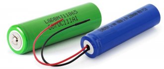
In recent years, it has become very popular to remake a multimeter by replacing the power supply from the original crown with a lithium-ion battery from cell phones and smartphones. For these purposes, in addition to the battery itself, you will need charging and discharging boards. They are bought on Aliexpress or other online stores.
The overdischarge protection board for such batteries is initially built into the battery in its upper part. It is needed so that the battery does not discharge beyond the nominally permissible limits (approximately 3 Volts and below).
The charging board does not allow the battery to be recharged above 4.2 Volts (link to aliexpress).
In addition, you will need a board that increases the voltage from 4V to the required 9V (link to aliexpress).
The battery itself fits compactly on the back cover and does not interfere with its closure.
First, the output voltage on the boost module must be set to 9 Volts. Connect it with wires to a multimeter that has not yet been converted and use a screwdriver to unscrew the required value.
You will have to make a hole in the case for a micro or mini USB charging connector.
The boosting module itself is located in the place where the crown should be.
Be sure to ensure that the wiring from the module to the battery is of the required length. In the future, this will allow you to easily remove the cover and, having halved the body, carry out an internal inspection of the multimeter if necessary.
After placing all the parts inside, all that remains is to solder the wiring according to the diagram and fill everything with hot glue so that nothing moves when moving the device.
It is advisable to fill not only the body with hot glue, but also the contacts with the wires in order to extend their service life.
A significant drawback of such a multimeter on a lithium-ion battery is its operation, or rather not operation, at subzero temperatures.
Once your multimeter sits in the trunk of a car or in a bag in the winter for a long time, you will immediately remember the battery.
And you might think, was such a change useful? Ultimately, of course, you decide, based on the operating conditions of the device.
Smartphone app
After the adapter is soldered, download the application from (active link to the application) and install it. Launch the application and connect the adapter. Everything should work. If you close the probes, you will hear a beep, which means everything is fine and you can use it. Initially zeros are shown:
And when you close the probes together, this word appears and the phone beeps.
Types of probes
Universal probes Probes, like conductors, are one of the main parts of a measuring device. With their help, it is possible to accurately determine the contact, analyze the presence of voltage and leakage. They are always included. There are several types of structures.
Universal
These devices contain PVC conductors, which tend to crack in hot weather. The tips themselves are made of stainless steel. They come with a set of additional attachments. Experienced electricians believe that these parts are unreliable because they quickly lose contact with the conductor.
Branded
The probes have wires with improved flexibility. The tips have excellent sealing, the handles are rubberized, so they are comfortable to work with. Such parts are provided with special caps that provide protection from dust and moisture.
For SMD mounting
Probe-tweezers for checking SMD components Devices are convenient to connect. They are used for periodic measurements during SMD type installation. The tips are needle-shaped and equipped with protective caps. Using probes, you can pierce the cable insulation, as well as clean the solder mask on boards and other surfaces.
"Crocodiles"
Also considered convenient for electrical work. They are much more effective than sharp electrodes and can prevent short circuits during operation. The sizes of these probes usually vary. The parts must be in a dielectric shell.
What to remember when taking measurements
Please note that it is impossible to accurately determine the battery charge with a multimeter. Using a tester, you can verify its performance and find out what power it has, but this does not allow you to draw reliable conclusions about its capacity. For this test, only rechargeable batteries are used.
It is strictly not recommended to check leaking batteries with a multimeter. Such a galvanic cell is not subject to subsequent use and must be disposed of. Moreover, damaged disposable and reusable batteries can be dangerous because they contain caustic substances that can damage the skin and mucous membranes.
It is necessary to measure the battery capacity with a multimeter in a dry place. It is strictly not recommended to use the tester at high humidity. The device must be located on a flat and stable surface.
When measuring the voltage in an element without a load, you cannot close the circuit for a long time. This may render the batteries unusable for future use. On average, the measurement lasts 0.5–1 second. This is enough to read the reading from the multimeter screen. It should also be noted that some types of multimeters are not designed to work with batteries and low-power batteries. Therefore, before work, you need to make sure that the measuring device is compatible with a certain type of element.
Purpose and types of wires for a multimeter
Inexpensive multimeters are equipped with appropriate probes. The conductors that lead to the probes play a big role in the correct testing of any electrical appliance. However, if contact is broken, the device is not able to accurately measure the existing voltage and determine the performance of a particular device.
Usually this part comes with a multimeter, but it is better to have a supply of conductors in case the main ones are broken. Most of them have PVC insulation, which begins to crack with prolonged use. Often these parts are universal, so they fit most meter models.
Conductors can be hard (rubber-sheathed) or elastic (silicone-coated). The latter option is considered the most practical, as it can easily be twisted and any other type of deformation. Such parts are considered reliable and are easy to use even during work in any conditions.
Rigidly insulated conductors are more suitable for performing voltage testing in places where there is little free space. Rubberized parts are considered safe because they do not allow electricity to pass through. Suitable for the event that a breakdown has occurred in the electrical appliance being tested.
Even if the multimeter is equipped with new leads and probes, it is necessary to take into account safety precautions - wear rubber gloves while working.
Determining the exact battery voltage
In order to find out the actual battery voltage yourself, you will need at least one accurate resistor with a nominal value of 2 or 2.2 kOhm with an error of 0.5%. This resistor value was chosen due to the fact that when a microammeter is connected in series with it, the total resistance of the circuit will be 5000 Ohms. Consequently, the current passing through the tester will be about 300 μA, and the needle will deflect to full scale.
I=U/R=1.5/(3000+2000)=0.0003 A.
If the tester shows, for example, 290 µA, then the battery voltage is
U=I*R=0.00029(3000+2000)=1.45 V.
Now knowing the exact voltage on the batteries, having one exact resistance and a microammeter, you can select the required resistance values of the shunts and additional resistors.
Required Parts
This is a tester that has a magnetoelectric mechanism to measure current, so it only measures DC current. The moving coil with an arrow is mounted on guy wires. Used in analog electrical measuring instruments.
Finding it at a flea market or buying it at a radio parts store won’t be a problem. There you can also purchase other materials and components, as well as attachments for the multimeter. In addition to the microammeter you will need:
If a person decides to make himself a multimeter with his own hands, it means that he has no other measuring instruments. Based on this, we will continue to act.

