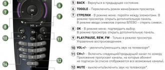
In the age of modern technology and technical progress, it is difficult to imagine your life without a TV that is controlled by a remote control. But what to do if the remote control is broken?
Of course, you can go to the store and buy a new remote control, but not everyone has the opportunity to do this immediately. If for some reason a person does not want to buy a new remote control, there is a simple solution: you can make the remote control yourself.
With the advent of smartphones, assembling a remote control with your own hands has become easier than ever and anyone can do it at home. But the main thing is that such a remote control can control any TV that has an IR port, as well as other household appliances.
Build process
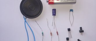
When starting to assemble the remote control, make sure that all the necessary tools and parts listed above are at hand. Assembly consists of several stages:
- Grind off the protruding side parts of the IR diodes on one side only with sandpaper;
- Glue 2 diodes together with superglue, pressing one element to the other with the smooth (ground) side. Wait for the glue to dry;
- Bend the legs of the diodes and bite off the excess parts with wire cutters;
- Solder the anode of one diode to the cathode of the other with a soldering iron. Do the same with the second IR diode;
- Then you need to solder the LEDs to the plug legs; the polarity when soldering is not important at this stage;
- Fill the soldering area with glue and wrap it with electrical tape;
- Insert the resulting device into the headphone jack;
- Download a program to control your TV from the Play Store and install it on your phone.
As you can see, there is nothing complicated in assembling a remote control for a TV; for this you do not need to have a higher education or be a radio physicist.
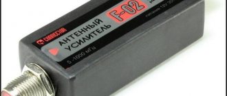
The infrared port returns to smart phones
Anyone can make a remote control for any equipment with their own hands. You don’t have to be a super physicist to do this – just follow the detailed instructions. But before we describe step by step how to make a universal remote control, here is one interesting fact.
Anyone who still remembers what mobile phones were like 10 years ago knows that many models were then equipped with an infrared port. It was used to transfer information (media files). But then it didn’t work out to use it as an element of the remote control. Now mobile phone manufacturers have again begun to supplement gadgets with infrared emitters. They give the smartphone another function - use as a remote control for home electronics.
Meanwhile, you don’t have to buy a new expensive smart remote control, because a similar device can be obtained from any Android phone.
For this you will need:
- smartphone;
- infrared diodes - 2 pieces (which are used in the TV remote control);
- glue;
- sandpaper;
- 3.2 mm plug;
- soldering iron
How to connect a smartphone and TV device
Controlling your TV from your phone is quite easy.
This requires a wireless connection. Moreover, both devices connect to the same network. Synchronization settings are made through direct activation of WiFi Direct. Or a router. If your TV does not have WiFI functionality, you can connect it via cable. By the way, sometimes this option is more acceptable, since the transmission speed over the cable can be higher, especially if the WiFi signal is weak. Before you can continue with the settings, make sure the following:
- The phone and TV are on the same network.
- The router has UPnP mode enabled.
- The firewall is configured correctly.
Article on the topic: Why they don’t show football on TV
If all of the above is observed, there should be no problems connecting the device.
By the way, if your TV does not have WiFi and you cannot synchronize it via the network, Xiaomi offers a solution using the infrared port of its gadgets. Moreover, you can control not only televisions, but also other household appliances in this way. Now let's move on to looking at the software.
Applications from TV manufacturers
Most TV manufacturers have dedicated companion apps for their smart TVs. These apps usually have everything you need to turn your smartphone into a full-fledged remote control. The app connects to your TV via Wi-Fi. These types of programs allow you to change the channel or adjust the volume, launch applications on the TV, and so on. Almost all smart TVs from Samsung, LG and Sony have similar programs. So just visit the manufacturer's website or take a look at the user manual.
Add a link to a discussion of the article on the forum
RadioKot >Schemes >Digital devices >Household appliances >
| Article tags: | Remote control remote controlAdd tag |
Universal teaching remote control
Author: GoldenAndy Published 09/01/2021 Created using KotoEd.
When there are more remote controls than hands or how not to become Shiva the Many-Arms
(picture from the Internet)
What the remote control can do.
A learning remote control is a remote control that can remember an IR message from another remote control and then try to reproduce it. But since there are many remote control command formats in the world, the task becomes non-trivial. Especially for the ATMEGA8 microcontroller.
But I hope that I have solved this problem at least partially.
Brief characteristics: ATMEGA8A controller 30 buttons Power supply 3-5 volts Battery voltage indication, parcel control (2 LEDs - red and green) Consumption in standby mode ~2 µA (at 3 volts)
The remote recognizes several common formats and attempts to emulate them according to specifications. Unknown formats are also analyzed and tried to be reproduced.
Recognized formats with emulation according to specifications:
- SONY (SIRC-12, -15, -20 bit), 40 kHz
- NEC, 38 kHz
- SAMSUNG, 38 kHz
- SHARP, 38 kHz
- JVC, 38 kHz
- RC5 (Philips), 36 kHz
Typical formats, emulated with a 38 kHz carrier:
- Format with constant pauses, encoding is carried out by pulse length, a separate start pulse is possible (like SONY). Up to 64 bits of data.
- Format with constant pulses, coding is carried out by the length of the pause, a separate start pulse and start pause are possible (as with NEC). Up to 64 bits of data.
- Format with constant pulses, encoding with different pause lengths (like SHARP). Up to 64 bits of data.
Unrecognized formats are emulated with a 38 kHz carrier.
- The remote control also tries to record such formats of messages, analyzing the lengths of pulses and pauses in order to reproduce them later. Depending on the complexity of the format, the remote control can store up to 16 or up to 32 pulses. More information about such preservation will be given below.
Initially, the remote control was made in a 12-button version, in the housing of a car remote control on the steering wheel. But then the scheme “matured” to 30 buttons.
The option for repetition is a 21-button Chinese remote control “IR remote control HX1838 for Arduino” or a maxi version - a 30-button remote control with clock buttons - a board measuring 115 * 40 mm.
History of development.
It so happened that I got the car in the “homeless” configuration. Those. there was minimal audio preparation, but there was no radio. Prology DVS-1140 was chosen as the head unit .
The main reasons for choosing are the picture from the rear view camera and support for flash drives and SD.
This “combine” came with a remote control. It's like a waffle with 40 buttons.
The remote control is not ergonomic at all. It's almost impossible to use by touch. Which automatically makes it impossible to use the remote control while moving. And I bought a universal learning remote control on Ali with a steering wheel mount. Here it is. The issue price is about $4.
10 buttons (volume control buttons on the back) + learning button.
Excellent training and very comfortable. About a year. Then it began to glitch, and then stopped working altogether. A fresh battery didn't help. The remote control seemed to be learning, when sending a command it sent something (it was visible on the phone’s camera), but no device responded to this message. And the remote control was put on the shelf for a long time. But the thought of restoring the remote control remained.
And now we got around to breathing new life into the remote control.
The first stage of development involved making a new board for the car remote control and writing the basic functionality for the remote control to work in the car. And in a short time, so that you have time to get a working remote control before going on vacation. The remote control worked, the trip was a success, about 3800 km were driven. The remote control successfully drove the entire trip and showed its best side.
The second stage of development is to teach the remote control to learn various commands of various remote control formats and use the acquired knowledge.
| Somewhere I have already seen the process of switching the processor into learning mode. Feel like Sarah Connor |
| “And the consoles will rise from the ashes of nuclear fire, and the war will begin to control the TVs!” |
 Thudum-tum-thudum!
Universal learning remote control.
Analysis of protocols.
IR control protocols vary. But most protocols boil down to the fact that the remote control sends data, encrypting it with the duration of IR pulses and/or pauses between pulses. Also, the information parcel may be preceded by a starting impulse of individual duration. In addition, in the vast majority of modern protocols, a pulse does not imply a constant glow of an infrared LED, but modulation of the carrier frequency by these pulses. And for different protocols this frequency is also different. For example, for RC5 it is 36 kHz, for NEC, Samsung - 38 kHz, Sony uses 40 kHz... There are other, more exotic formats with a carrier frequency of up to 56 kHz. Modulation allows the receiver to more clearly distinguish the message from the remote control from external light and interference. In addition, this allows, while maintaining average power, to increase the current through the emitting diode, which helps to increase the range.
This design uses 38 kHz as the base carrier frequency for unknown protocols. However, for known formats, the carrier frequency is set according to the format. To train the remote control, a receiver with a frequency of 38 kHz (type TSOP1838, HX1838, VS1838, HX1838, VS1838) is used. It accepts both 36 and 40 kHz satisfactorily...
There are quite a lot of different formats. For example, RC5. The so-called bi-phase, Manchester coding. Easy to recognize, easy to decode.
Or a format with a fixed pause between pulses (Sony). Here the starting pulse and then pulses of various lengths with fixed pauses are clearly monitored.
A format with a fixed pulse and different pauses (NEC, JVC, Samsung, etc.)... Here, too, there is a start pulse, a start pause, then there are pulses, and the information is encoded by pauses between pulses.
Format with information encoding by pause lengths (Sharp). It can be seen that the message has three durations - pause 1, pause 2 and impulse.
Another coding option. Some nameless fan remote control. Information is encoded by pulse length with a fixed pulse repetition period.
The above graphs (by the way, real ones, taken by a logic analyzer) show that the different durations of pulses, pauses, start pulse and start pause differ quite greatly from each other in duration. At least 2 times. Often, all these durations are also multiples of the shortest one. This allows, by recording the signal in the form of pulse durations and pause durations in a buffer array, to analyze and group these durations. A tolerance of ±25% is in most cases sufficient to distinguish one duration from another. Well, in any case, I didn’t have any problems with receiving the parcel correctly. The resulting durations are added to an array. Durations in the buffer array are assigned indices, after which you can already work with the index array. It is lighter and, in the case of the 8-bit ATMEGA8, even faster.
Moreover, if this is an unknown format, then for this format it is possible to save an array of ordered durations and indexes of pulse and pause durations for the entire message.
From the above graphs it can be seen that the number of ordered durations is from two to four. Four is good. Because it is encoded in two bits. An unknown protocol with two durations is generally encoded with one bit per send/pause duration, with three or four - two bits.
The remote control has 30 buttons. EEPROM in ATMEGA8 - 512 bytes. Of these, 10 bytes are occupied by service information. If the remaining information is divided into 30 buttons, you get 16 bytes of data per button.
These 16 bytes are divided like this:
The type of saved package is 1 byte. Number of information pulses - 1 byte Array of measured durations - 4 bytes Clock period - 1 byte Pause duration between sendings - 1 byte.
There are 8 bytes left for writing data. Or 64 bits.
For recognized formats, this allows 64 bits of data to be stored.
Simple mathematics shows that for unrecognized formats, when the durations of both bursts and pauses are stored, with 2-bit encoding we can store a maximum of 32 duration indexes. In reality, this will be a maximum of 31 indexes - 16 impulses and 15 pauses. With 1-bit encoding (when there are only two durations) we can store up to 63 duration indexes. (32 pulses, 31 pauses).
In principle, I believe that for most equipment such as televisions, media players, cable/satellite decoders, etc. - It's enough.
Scheme.
Clicking on the diagram will open it larger. And for those who don't need it, here's the diagram in PDF.
The buttons are connected to the controller by a 2 x 15 matrix. The applied controller can exit the most energy-saving mode only by applying a low level to the INT0 or INT1 input. INT1 is occupied by the photodetector. That leaves INT0. Accordingly, the first wire, the column of the button matrix, is connected to the INT0 input, and the second is connected to it through a diode. Unfortunately, such a connection will not allow recognizing the simultaneous pressing of buttons on the same line (SW1 and SW16, for example). The first 15 buttons will have priority. But for remote control this is not critical.
Button SW1 is special. Pressing it for a long time (more than 2.5 seconds) enters the remote control into learning mode. Accordingly, for this button, auto-repeat of commands when holding the button is disabled. The remaining 29 buttons are absolutely equivalent from the program's point of view. And if you wire the board yourself, you can place them as you like, in any order and configuration. There are also no requirements for the placement of the SW1 button, but for the convenience of using the special function, it is advisable to place this button somewhere on the edge of the keyboard field. For example, in two versions of the board I placed this button in the upper left position. When training the remote control, you can assign a command to this button that does not require a long press and hold of the button. For example, on/off, input selection, play/pause, etc.
If you are planning a stripped-down version of the remote control with fewer buttons, you can remove any buttons except SW1 (otherwise you will not be able to put the remote control into learning mode).
A photodetector is connected to the INT1 interrupt input. To reduce current consumption, the power of the photodetector is turned on only when teaching the remote control.
The controller's power supply is additionally decoupled by a diode and capacitors C2, C3, so that power supply interference during command transmission does not affect the operation of the controller so much. SS14 is used as a decoupling diode - a fairly powerful (40 V, 1 A) Schottky diode. Oddly enough, at low currents it has a lower voltage drop than the originally planned small BAT46.
Printed circuit board.
2 versions of the printed circuit board have been developed.
Option number one. "Spherical remote control in a vacuum." This is just a board, without fitting into any case. Size 115 x 40 mm, 30 tact buttons. The wiring is one-sided, with a relatively small number of jumpers.
Gerberas.
Option number two. The board layout is made for a Chinese remote control.
Hint: If you buy a set from the Chinese - a remote control plus a receiver - then you don’t have to look for a photoreceiver separately. If you're lucky, the receiver board also has a red LED of size 0805.
Features of the board. The native Chinese board is about 0.9 mm thick. Accordingly, your board must also be made on thin (0.8 - 1.0 mm) PCB. Since the top side of the board is also a plane for gluing the front film with rubber bands, there should be no protruding elements on this side.
Adapters should ideally be soldered with a very, very thin wire (hair from mgtf, for example) with a minimum amount of solder. Only keyboard polling signals pass through the transitions; there are no power circuits there. Tin the contact pads with a minimum amount of solder and then, perhaps, walk over them with a stream of air from a soldering hair dryer so that all the nodules/lumps are removed.
Information LEDs of standard size 0805 are soldered on the back side of the board, upside down, with the crystal in the hole. So that the diode lens does not protrude above the front of the board. Then they will shine through the sticker, but will not lift it.
Photodetector. The Chinese receiver is too thick, almost 5.5 mm. And the space between the board and the bottom surface of the case is 4 mm. Accordingly, in order not to look for expensive flat receivers (and Vishay has such), a hole is drilled in the lower plane of the case for the receiver lens. You can drill with a 2 mm drill, and then select a thicker chamfer from the inside. You can also peel off the metal screen of the receiver. At least 0.5 mm will also be gained.
Gerberas.
Fuses and firmware.
Fuses:
For those who are closer to the numbers, here they are: High 0xD1 Low 0xE4
Firmware.
To flash the firmware, you need to solder the wiring from the programmer to the corresponding contact pads - Ground (GND), MO(MOSI), MI(MISO), SCK, Reset. Connect +5 volts from the programmer to the “+” contact of the battery compartment. The battery must be removed. If the programmer supports logical levels of 3.3 volts when flashing, the “+” from the programmer can not be connected to the remote control, but flashed with the battery inserted.
On the version of the board for a small Chinese remote control, I also added a separate patch + power supply, so that it would be easier to supply power from the programmer.
In principle, the firmware has been debugged and tested. But if any errors are suddenly discovered or additions are made, I will post the updated firmware here and on my blog.
Brief instructions for learning the remote control and its use.
Power supply to the remote control. Data about saved commands is stored in the EEPROM of the controller. A checksum is used to verify data integrity. When power is applied, the remote control turns on the green control diode and checks the data stored in the EEPROM. If the data is valid, after about 0.2 seconds the LED will go out and the remote control will go into energy saving mode. If there is no data or it is invalid, the red LED will light up and the remote control will format the EEPROM to the required information storage structure. After a little more than a second, the LED will go out and the remote control will go into energy saving mode.
Remote control mode. In normal mode, pressing a remote control button sends a command recorded on that button.
In this case, while the command is being sent, the green control LED lights up or, if the battery voltage is below 2.7 volts, the red LED lights up. All buttons except the first one, when held, send a command repeat as long as the button is pressed. When you press the SW1 “Set” button, the remote control will send a command and one repetition, then the time will be counted to enter the training mode. If there is no written command on the button, the control LED lights up briefly and no data is sent.
Training mode. A long press (more than 2.5 seconds) of the SW1 “Set” button puts the remote control into learning mode. When you press and hold the button, the red LED lights up after 2.5 seconds. When the button is released, the red and green LEDs begin to flash. In this mode, the remote control turns on the photodetector and waits for a message from the external remote control.
Within 6 seconds, you must point the external remote control at the photodetector and press the required button. If the remote control correctly recognizes the command, the green LED will begin to blink rapidly and you must press the button on the remote control within 6 seconds to which you want to record the received command. The green LED lights up and stays on for a little over a second. Data about the received command is stored in EEPROM. If you do not press any button within 6 seconds, the remote control will return to standby mode. After saving the command, the remote control will return to learning mode and will wait for the next command from the external remote control. If the remote control does not recognize the command, the red LED lights up for about a second, signaling an error, after which the remote control will return to learning mode and will wait for the next command from the external remote control. If no command is received by the remote control within 6 seconds, the remote control will go into standby mode.
Deleting saved commands. To delete a command stored on a button from a button, you must put the remote control into learning mode. In learning mode (red and green diodes flash), you must press the button from which you want to delete the saved command. The red diode will begin to flash rapidly and within 2 seconds you need to press the SW1 “Set” button to confirm the deletion of the command. If a saved command is successfully deleted, the green LED will light up for a little over a second and the command will be erased from non-volatile memory. If you do not press anything during these two seconds or press any other button (not SW1), the deletion will not occur, the remote control will return to learning mode.
Files:
Gerbera remote control for 21 buttons Firmware Gerbera remote control for 30 buttons Diagram in PDF
All questions in the Forum.
| What do you think of this article? | Did this device work for you? | |
| 47 | 2 | 2 |
| 0 | 0 |
New work for the remote control system of an old TV
Rating: / 5
Details Category: Remote control Published: 06/30/2018 11:30
In the 80s and early 90s, TVs 2-USTST and 3-USTST appeared. But the time of USCT has passed, but some components and modules of such TVs can be used almost for their intended purpose. For example, a remote control system designed to switch eight programs can be adapted to remotely transmit a three-bit binary code or to control loads or devices.
Pros and cons of controlling lighting from a distance
Main advantages:
- economical energy consumption;
- ease of use, especially if you need to control lighting at several points;
- ease of installation - no need to break down walls or lay a separate branch of electrical wiring;
- possibility of pairing with a dimmer for smooth switching on of light;
- saving on consumables - a wireless system requires wires and cables;
- comfortable process of turning the light on and off;
- the user is not subject to an emergency power outage - the sensor cabinet and the machine are connected via radio waves, and the lighting is controlled without connecting to a local network;
- safety - remote lighting switches operate from small current values, which are not dangerous to humans;
- the ability to control the backlight both from the remote control and from a smartphone or tablet with the installed program;
- the presence of a presence effect helps to protect the apartment from burglars.
Disadvantages of remote lighting control:
- the cost of such devices is slightly higher than that of stationary switches;
- problems may arise related to a poor Wi-Fi signal or its absence, or a dead battery in the remote control;
- complexity of setup - strict rules must be followed, otherwise there will be errors in the operation of the device;
- precise adjustment of trigger conditions is required;
- the possibility of false alarms - to remove this effect it is necessary to develop systems with several sensors.