Nightingale trill generator
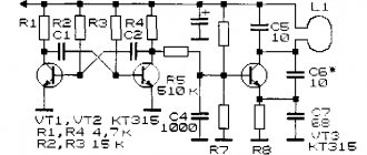
The nightingale trill generator, made on an asymmetric multivibrator, is assembled according to the circuit shown in Fig. 1. The low-frequency oscillatory circuit formed by the telephone capsule and capacitor SZ is periodically excited by pulses generated by the multivibrator. As a result, sound signals are formed that resemble nightingale trills. Unlike the previous scheme, the sound of this simulator is not controlled and, therefore, more monotonous. The sound timbre can be selected by changing the capacitance of the capacitor SZ.
Rice. 1. Generator-simulator of nightingale trills, device diagram.
Refinement of standard devices
Many people are not happy that the touch zone on the panel is quite small, and to record a signal you need to touch it in the indicated place. Let's give an example of how you can increase the area of indirect surface contact.
Increasing the sensor sensitivity area
You should take the wire and carefully solder it to the place where the signal is supplied from the sensor on the touch board (for this you need to study the circuit diagram of the device). The connected wire is laid around the perimeter of the housing. As a result, such a frame will make it possible to trigger the sensor when touching the front panel without amplifying the signal level.
It should be noted that such an improvement will void the manufacturer's warranty.
Duck quack simulator
The duck quack simulator (Fig. 3), proposed by E. Briginevich, like other simulator circuits, is implemented on an asymmetric multivibrator [R 6/88-36]. The telephone capsule BF1 is included in one arm of the multivibrator, and the LEDs HL1 and HL2 connected in series are included in the other.
Both loads work alternately: either a sound is made, or the LEDs flash - the eyes of the “duck”. The tone of the sound is selected by resistor R1. It is advisable to make the device switch based on a magnetically controlled contact, which can be homemade.
Then the toy will turn on when a disguised magnet is brought to it.
Rice. 3. Scheme of a duck quack simulator.
How to make a diagram
Many homeowners, in order to create the correct project for the electrical supply of their home, engage specialists who know the requirements of the PUE by heart and, taking them into account, effortlessly place all these cables, wires, RCDs, sockets and overhead lights. The project drawn up by a specialist will be approved without unnecessary quibbles, and when the wiring is ready, the inspector will accept it the first time. But people who firmly know Ohm's law draw up electrical wiring diagrams independently and successfully.
Proper electrical wiring lasts about 20 years.
At the stage of drawing up an electrical wiring diagram in a private house, you need to choose whether the wiring will be laid in a closed or open way: in most cases, in stone houses they choose closed, in wooden houses - open.
AlexIvKUser FORUMHOUSE
I did it openly, because I do not accept idiocy in the form of chiseling and drilling logs for hidden wiring.
To lay power lines in a hidden way, they can use a corrugated sleeve made of non-flammable material (or maybe not, it depends on the material of the walls). To conduct an open power line, decorative twisted retro wiring is used, which is attached to insulators or less aesthetic cable channels.
A practicing electrician and FORUMHOUSE user with the nickname Kostya Ivanov tells how to create a wiring diagram. According to him, most people start by forming a diagram of the shield, but there is an easier way. You need to start by placing technical points on the house project, first - distribution panels. Different power supply schemes can be implemented, but it is better that there is more than one panel. This is always true in a country house.
Electrical installation64FORUMHOUSE user
They are building a two-story house, which will have a full basement, a garage and other outbuildings. It is more profitable to install separate panels on the second and ground floors, in the garage, etc. There are also cases when repairs are done gradually and the installation of the existing main panel will entail alterations.
Next, you should place socket points on the house plan for powerful loads (oven, living room air conditioner, etc.), loads with increased protection sensitivity (dishwasher, washing machine, outdoor sockets) and loads with uninterrupted operation (pumping station, heating boiler, signaling). Each of these devices must have an individual line from the panel, and each such line must have its own protection.
Ivanov KostyaForumHouse user
So in the panels we draw the first automatic machines and RCDs (residual current devices).
Then the house plan should be divided into zones and each designated with its own color, adhering to the following rules:
- Each line should have no more than two residential premises: if the heating boiler suddenly fails, heaters will have to be installed in the rooms, and with this approach there will be two heaters per line.
- Do not separate overhead lights from sockets. This will reduce the number of wires on the walls (and the risk of drilling into the wire). Each room will be completely turned off, but if the division of the house into zones is done correctly, then light will enter the emergency room through the door, and there will be working sockets nearby.
The next stage: “arrangement of furniture” in the plan and choosing a place for sockets. It is necessary to provide for everything: where the air conditioner will be, where the laptop is, the reading lamp by the chair, the table lamp on the bedside table, the wall lamps, the socket for the vacuum cleaner. After this, you need to arrange the furniture in a different order and add the number of sockets; a lot is not a little, but in the life of the owners of this house there will not be endless extension cords and hanging cords.
Sockets of the same color zone are brought together into a common line, which is pulled to the nearest panel: new machines and RCDs appear in the panels.
Now it’s the turn of the overhead light: you need to mark switches and lamps on the plan; for convenience, it is better to turn on some lamps through walk-through switches. It is also recommended to power street lamps at the exits to the house from walk-through switches to organize a rational and comfortable method of lighting: the owner left the house early in the morning, while it was still dark, locked the doors, then turned off the lights and went to work...
In the diagram, the overhead light is combined with sockets, and each color zone has its own lamp with its own switches. This way the plan is not overloaded with other lines leading to the shields. But if there is a need to separate the overhead light from the sockets, you need to make another scheme with a different color division of the building; combine different rooms into groups and extend new lines to the panels. New automatic devices and RCDs will appear in the panels.
Wiring without distribution boxes is the dream of any novice installer: to draw a separate line with an RCD from the switchboard to each outlet. But if there are many outlets in the room, you have to combine consumers into groups and run cables to the junction box. In the diagram you can see the place where they are mounted - where the vertical and horizontal lines intersect.
Many homeowners prefer to make boxes in the hallway; there is always less furniture there, and if the box has to be opened to run through the cable, it is morally easier to damage the wall decoration in the hallway than in the room. And you definitely don’t need to make boxes under the ceramic tiles.
The kitchen requires special attention when drawing up a diagram. From an ergonomic point of view, this is the most difficult area, in which sockets, boxes and lines are most dependent on the number of household appliances and furniture. The worst thing is that in most cases electricity is installed when it is unknown what kind of furniture will be there and what kind of equipment the housewife will need. There is a technique that experienced electricians often offer to customers:
place 3-4 lines (one for an electric stove or electric oven, two more for conventional kitchen appliances, one more for a dishwasher or washing machine) on the kitchen working wall, leave a supply of wires, roll them into a hoop, cover them with cardboard on top and preserve them them, begin plastering work.
And only then, having received a kitchen design with all the cabinets, table, space for the dishwasher and stove, draw sockets. To implement them, you will have to strip the walls: this method is more expensive on all sides, but the sockets will be located conveniently, and not above the gas stove or behind the built-in closet or other structures.
Light switches (if they are not built into the furniture) need to be prepared together with sockets, leaving tails to connect the lamps. If built-in, the lighting is connected to a double socket for the hood.
When working on the diagram, it is important not to forget utility rooms, attics and basements and take into account possible changes. Country life is designed in such a way that today in the garage there is only light and an outlet for a vacuum cleaner, but tomorrow it may have “a drilling or lathe, a welding station, an automatic gate, a mini-car wash... and for working outside it would be nice to place an outlet ( under an RCD) in the garage or on the garage...” Taking this into account, the garage should have not just a shield, but a large shield, with a reserve for 5-6 positions.
Another important recommendation from a professional:
first you need to install the water supply and heating, and then lay out the electrical part so that it doesn’t turn out that the boiler needs to be installed where the distribution box is already hanging.
Let's summarize: by drawing up such a diagram on the building design with all the partitions and doors, the homeowner will know the number of all lines, know what kind of protection they need, how and where the sockets will be located. And such a document will become an excellent basis for the estimate: it is easy to calculate how many sockets and switches need to be purchased, how many meters of wires will be required and what additional materials will be needed.
Rain noise generator
Rice. 4. Schematic diagram of a “rain noise” generator using transistors.
The “rain noise” generator described in the monograph by V.V. Matskevich (Fig. 4), produces sound pulses that are alternately reproduced in each of the telephone capsules. These clicks vaguely resemble raindrops falling on a windowsill.
In order to make the droplet fall random, the circuit (Fig. 4) can be improved by introducing, for example, a field-effect transistor channel in series with one of the resistors. The gate of the field-effect transistor will be an antenna, and the transistor itself will be a controlled variable resistor, the resistance of which will depend on the electric field strength near the antenna.
Electronic telegraph key
The electronic telegraph key on one K561J1E5 chip (Fig. 14) is made according to the traditional scheme for such keys [RL KB and VHF 1/96-23]. The relaxation generator is assembled on logic elements with different RC circuits responsible for generating dashes and dots.
Rice. 14. Scheme of an electronic telegraph key.
When you press the telegraph key (closing the charging circuit), the group of capacitors C1 - SZ (dash) or C2, SZ (dot) is charged. When the voltage at the input of logic element DD1.1 exceeds a certain threshold level, it will switch and the output will be set to logical zero.
The charging process of the capacitors will be interrupted, and they will begin to discharge through resistances R2 and R3. When the voltage on the capacitors drops below a certain value, the first logic element will switch again, and the process of charging/discharging the capacitors will repeat.
This process will continue as long as the contact group of the telegraph manipulator is closed. The duration of the dots and dashes is determined by the time constants of the charging and discharging circuits (RC). Capacitors C1 - SZ must have low leakage currents.
For sound indication of generated telegraph signals, a generator is designed, made on the third and fourth elements of the microcircuit.
The generator is loaded onto a piezoceramic emitter of the ZP-19 type. When using an inductive emitter (telephone capsule) in series with it, it is necessary to include a separating capacitor with a capacity of more than 0.1 μF.
Simultaneously with the sound, a light indication on the NI LED (AL307) was introduced into the circuit, which allows you to visually monitor the presence of telegraph parcels. To switch the circuits of the transmitting device, a buffer cascade on transistor VT1 (KT315), loaded on a relay, is used.
As with other simple telegraph keys that use a similar method of forming dots and dashes, this design has the same disadvantages: the need to adjust the dot/dash duration ratio with resistance R1 when the transmission speed changes.
The mechanical part of the manipulator can be made from a piece of hacksaw blade with adjacent contact groups. As such contacts, you can use the contacts of a disassembled large relay.
Electronic drum attachment
Electronic drum - a circuit that generates a sound signal of the appropriate sound when touching a sensor contact (Fig. 5) [MK 4/82-7]. The operating frequency of generation is in the range of 50...400 Hz and is determined by the parameters of the RC elements of the device. Such generators can be used to create a simple electric musical instrument with touch control.
Rice. 5. Schematic diagram of an electronic drum.
Scope of application
Initially, this type of switch was planned to be used to turn on/off lighting, but the design turned out to be so successful that the scope of its application has expanded significantly. Today, most modern household appliances have touch controls; examples include kitchen stoves, hoods, microwaves, etc.
Kitchen hood Cata Midas 900
The only limitation on connecting to touch switches is the power of the equipment; its permissible parameters are indicated in the device passport.
Additional functionality
Modern technical base has made it possible to install microcontrollers in the electronic control unit of a touch switch, which has significantly expanded the functionality of switches and allowed them to fit into the concept of a smart home. Such switches can be controlled by voice, infrared or radio remote control, smartphone via WI-FI or a programmable timer.
The touch switch can be connected to the smart home system and controlled using a mobile phone
Touch switches can be used in conjunction with sensors that respond to motion or light levels. In the first case, such devices turn on a lamp, table lamp or other lighting fixtures when someone enters a room, such as a bathroom. With the second implementation option, the light will turn on at a low light level.
Sesoo triple touch switch and motion sensors
Some manufacturers, for example, Livolо, produce touch switches with a dimmer function or that control combined sockets, to which almost any household appliance can be connected.
Livolo touch switch with socket block
Electronic violin with touch controls
Rice. 6. Circuit of an electronic violin using transistors.
A sensor-type electronic “violin” is represented by a circuit given in the book by B.S. Ivanov (Fig. 6). If you put your finger on the touch contacts of the “violin”, the pulse generator, made on transistors VT1 and VT2, is turned on. A sound will be heard in the telephone capsule, the height of which is determined by the electrical resistance of the area of the finger applied to the touch plates.
If you press your finger harder, its resistance will decrease, and the pitch of the sound will correspondingly increase. The resistance of the finger also depends on its humidity. By changing the degree of pressing of your finger to the contacts, you can play a simple melody. The initial frequency of the generator is set with potentiometer R2.
Electronic traffic light model
The electronic traffic light model (Fig. 4) allows you to alternately switch multi-colored LEDs, simulating the operation of a real traffic light [Рл 10/98-15].
The timing circuit of the generator (R2, C2) determines the switching frequency of the green and red LEDs, and the circuit R1, C1 determines the glow time of the yellow LED. The duration of the green and red LEDs is about 10 seconds and is determined by the time constant R2C2, where the resistance is expressed in MOhms and the capacitance in μF.
Rice. 4. Electronic “traffic light” circuit.
Electric musical instrument
Rice. 7. Diagram of a simple homemade electric musical instrument.
Electric musical instrument based on a multivibrator [V.V. Matskevich] produces rectangular electrical pulses, the frequency of which depends on the resistance value Ra - Rn (Fig. 7). Using such a generator, you can synthesize a sound scale within one or two octaves.
The sound of rectangular signals is very reminiscent of organ music. Based on this device, a music box or organ can be created. To do this, contacts of various lengths are applied around the circumference of a disk rotated by a handle or an electric motor.
Pre-selected resistors Ra - Rn are soldered to these contacts, which determine the pulse frequency. The length of the contact strip determines the duration of the sound of a particular note when the common movable contact slides.
Blown fuse indicator
L. Teslenko's fuse blown indicator (Fig. 10) contains a pulse generator on a microcircuit and an LED indicator [P 11/85-44].
Rice. 10. Fuse blown indicator diagram.
When the fuse is intact, a high level voltage is supplied to the inverter input (pin 8 of the DD1 chip), prohibiting the operation of the generator.
Once the fuse blows, pin 8 is connected to the common bus through the load resistance. The generator will start working, and the LED will blink at a frequency of about 5 Hz.
To indicate a blown fuse when the load is “broken,” it is advisable to include a resistor of about 1 MOhm in parallel with the load resistance.
Simple color music using LEDs
A color and musical accompaniment device with multi-colored LEDs, the so-called “flasher,” will decorate the musical sound with an additional effect (Fig. 8).
The input audio signal is divided by simple frequency filters into three channels, conventionally called low-frequency (red LED); mid-frequency (green LED) and high-frequency (yellow LED).
The high-frequency component is isolated by the chain C1 and R2. The “mid-frequency” component of the signal is isolated by a sequential type LC filter (L1, C2). As a filter inductor, you can use an old universal head from a tape recorder, or the winding of a small-sized transformer or inductor.
In any case, when setting up the device, you will need to individually select the capacitance of capacitors C1 - S3. The low-frequency component of the sound signal passes freely through circuit R4, NW to the base of transistor VT3, which controls the glow of the “red” LED. “High” frequency currents are short-circuited by the capacitor SZ, because it has extremely little resistance to them.
Rice. 8. Simple color and music installation using transistors and LEDs.
To help car enthusiasts
This section is devoted to radio-electronic devices for cars . Here you will find a large number of circuits: digital tachometers , UZ installation devices, electronic ignition circuits , battery chargers , wiring diagrams for various domestic cars and many other electronic devices. We also invite everyone to the forum on automotive electronics, where competent specialists and forum participants will try to answer your questions.
Car devices:
- On-board computer for VAZ with color display and touchscreen (for ECU January)
- On-board computer for Bosch ECU 7.9.7+ on MSP430
- On-board computer for Bosch ECU 7.9.7+ on MSP430 (version 2)
- On-board computer for VAZ 2110
- Mini instrument panel on LCM12864 and ATmega64 display
- Clock - Tachometer - Thermometer - Voltmeter based on ATmega16 MK and LCM12864 graphic display
- Mini on-board vehicle for a car
- On-board minicomputer
- On-board computer (clock, two-channel thermometer, voltmeter on ATmega8 and LCD 16x2)
- Upgrading the on-board computer to ATmega8
- On-board computer based on AVR microcontroller
- A simple on-board computer for Italian cars and VAZs
- Reverse engineering of the Daewoo Nexia diagnostic protocol
- Digital speedometer, clock and thermometer for car
- Digital car speedometer based on GLCD
- Speedometer on PIC16F628A
- Car clock - voltmeter on ATtiny261
- Fuel and battery voltage indicator for car V.4
- Rear view mirror data display
- Simple heater control unit VAZ-2110
- Information screen for iPod
- CAN towbar coordination unit and alarm system
- Car siren on PIC with recording of audio fragments
- Police quack (siren) on a PIC microcontroller
- Thermometers and voltmeter for cars on PIC controllers
- Automotive digital voltmeter on MK
- Pointer voltmeter with extended scale 10…15 V
- Voltmeter with an accuracy of 0.1 V
- Multi-level voltage indicator
- Additional regulator for car generator
- DIY cable tester version 2.0
- Auto electrician tester for ATmega
- Automotive indicator probe with 1 V resolution
- Automotive test indicator
- Voltage indicator for moped
- Connecting GSM and GPRS trackers to the on-board network with a backup power supply
- Turn signal - running fire on thyristors
- Controller American size
- Autolight - control of external car lighting devices
- Running lights controller on ATmega like in a premium car
- DRLfar - daytime running lights as high beam headlights
- Daytime running lights control unit
- A simple car “forget-me-not” for DRLs
- DRL control unit
- Automatic headlight switching
- Automatic anti-glare flashlight
- Smooth high beam switch-off
- Device for smoothly switching on/off light in the car interior
- Smooth dimming of interior light
- LED driver for automotive lighting equipment
- Brake light fault indicator
- Sound indication device in the fuse box
- Remaking an old car flasher
- Fuel flow meter for car
- Device for modifying the physical properties of hydrocarbon fuel
- Reducing the energy consumption of the Webasto preheater
- Car cooling fan soft start relay
- Cooling system relay VAZ-2103…2108
- Simple tachometer with large numbers on ATmega8 and LCD 16×2
- Universal tachometer for MK PIC16F628A
- LED tachometer scale based on LM3914 chips
- Tachometer using MC14553 chip
- Tachometer with dot scale on 74NS chips
- Tachometer with dot scale on 40XX chips
- Tachometer with LED dot scale on popular logic chips
- Tachometer
- Tachometer-2
- Tachometer-3
- Electronic tachometer for car
- Electronic tachometer for motorcycle
- Motorcycle gear indicator
- On-board computer for a motorcycle with LCD from Nokia 6280
- Motorcycle improvement: emergency warning and thank you functions
- Controlling the heated windshield of a car on MK
- Automatic control of wipers and windshield washer for Niva
- Windshield wiper control unit BUS-01
- Windshield wiper stroke regulator
- Digital wiper control unit
- Pause relay for rear wiper
- Glass closer
- Car steering column joystick controller
- DIY parking sensors (Arduino)
- Brake fluid level indicator
- Handbrake warning light
- Radiator water level indicator
- Bluetooth Pressure Gauge
- Oil pressure warning indicator
- Radiator water level indicator
- Automotive temperature gauge
- Sound indicator "anti-sleep"
- Control module for electric lock drives
- LF spectrum analyzer for automotive suspension data analysis
- Balancing technology
- On-board control system with voice information output
- Car dashboard backlight controller
- On the dashboard
- Radar detector
- ATX-compatible computer power supply for car
- Power supply of radio equipment from the vehicle’s on-board network
- Car alarm blocker
- CAN interface bus converter to USB
- Generator for checking odometers
- Speedometer winder for NE555
- Winding up mileage readings in 3-phase speedometers (KAMAZ, etc.)
- Deception of the standard odometer
- Combiset adapter
- Electronics for a spotter from what is at hand
- Soft start of DC starter motor
Ignition:
- Diagnostics of high-voltage electrical equipment of cars
- Autostart gasoline engine
- DIY start-stop button for a car
- Car strobe flashlight on PIC
- Device for setting the ignition timing
- Automotive stroboscopic devices STB-1 and "Auto-Iskra"
- Car strobe light for setting OZ
- Automotive strobe light for adjusting ignition angle advance
- Universal digital switch (motorcycles)
- Contactless electronic ignition system breaker
- Blocking generator on a field-effect transistor in thyristor ignition
- Electronic ignition unit
- Ignition timing corrector - 1
- Ignition timing corrector - 2
- Octane corrector attachment
- Device for setting the ignition timing
- Electronic distributor for 6-cylinder internal combustion engines
- Electronic distributor ET-6S for 6-cylinder internal combustion engine
- Electronic distributor for 4-cylinder internal combustion engine
- Electronic distributor for 2 or 4-cylinder internal combustion engines with start synchronization ET2-4S
- Improved ignition unit
- Device for monitoring ignition systems
- Optimal ignition timing generator
- Electronic ignition system for car heater
- Electronic ignition
- Electronic ignition - 2
- Stabilized electronic ignition unit
- Ignition system for "SAMARA"
- Thyristor electronic ignition unit
- Transistor ignition unit with octane corrector
- Ignition system without runner
- Electronic ignition for motorcycle
- Electronic ignition IZH – Jupiter
- Electronic ignition switch KET - 1A
- Electronic stand “Car contact ignition system”
Chargers and everything for batteries:
- Buffer charger for car battery
- Car charger from an ATX computer power supply
- Converting a computer power supply unit LC-200C into a charger for car batteries
- Smart charger - version 2
- Smart Charger - Version 3
- Smart Charger - Version 4
- Smart Charger - Version 5
- Automatic charger of car batteries on PIC16F628A using triac control
- Powerful pulse charger for car battery
- Staged charge-discharge device
- Charger for car batteries with adjustable charging current 0-5 A
- Automatic charger for car lead-acid batteries
- Charger for car battery 12V
- Dual channel charger/discharger
- Desulfating charger circuit
- Charging batteries with asymmetric current
- Charging and desulfating automatic machine for car batteries
- Charger for starter batteries
- Automatic charger
- Rectifiers with electronic regulator for charging batteries
- Charger for car batteries
- Reliable thyristor controlled charger
- Push-pull inverter with pulse current amplifier
- Jump Charger
- Starting device
- Inverter power supply for starting a car (starter)
- Reconditioning of lead batteries
- Restoring and charging the battery
- Battery regenerator
- Electrolyte production
- Car battery discharge sensor in the cigarette lighter connector housing
- Low battery indicator
- Battery electrolyte level indicator
- Battery current indicator
- Battery voltage indicator
- Simple temperature compensated voltage regulator
- Voltage stabilizer for battery
- Garage rectifier GV-3
Electrical diagrams of cars:
- Electrical diagram of a VAZ-21011, VAZ-21013 car
- Electrical diagram of the VAZ-2101 car: Fuses
- Electrical diagram of the VAZ-2105 car
- Electrical diagram of a VAZ-2106, 21061 and 21063 car (1976-1987)
- Electrical diagram of a VAZ-2106, 21061, 21063 and 21065 car (1988-2001)
- Electrical diagram of the VAZ-2107 car
- Electrical diagram of the VAZ-2107 car (2 versions)
- Electrical diagram of a VAZ-2108, VAZ-2109 car
- Electrical diagram of a VAZ-21093, VAZ-21099 car
- Electrical diagram of the VAZ-2110 car
- Electrical diagram of the VAZ-2114 car
- Electrical diagram of the VAZ-2115 car
- Electrical diagram of the VAZ-2121 (Niva) car
- Electrical diagram of the VAZ-21213 (Niva) car
- Electrical diagram of the Moskvich M-412 car
LED electronic “guess the color” toy
The electronic machine is designed to guess the color of the LED that turns on (Fig. 9) [B.S. Ivanov]. The device contains a pulse generator - a multivibrator on transistors VT1 and VT2, connected to a trigger on transistors VT3, VT4. A trigger, or a device with two stable states, alternately switches after each of the pulses that arrive at its input.
Accordingly, the multi-colored LEDs included in each of the trigger arms as a load are illuminated in turn. Since the generation frequency is quite high, the blinking of the LEDs when the pulse generator is turned on (by pressing the SB1 button) merges into a continuous glow. If you release the SB1 button, generation stops. The trigger is set to one of two possible stable states.
Since the switching frequency of the trigger was quite high, it was impossible to predict in advance what state the trigger would be in. Although there are exceptions to every rule. Players are asked to determine (predict) which color will appear after the next launch of the generator.
Or you can guess what color will light up after releasing the button. With a large set of statistics, the probability of equilibrium, equally probable illumination of LEDs should approach the value of 50:50. For a small number of attempts, this relationship may not hold.
Rice. 9. Schematic diagram of an electronic toy using LEDs.
Selecting a touch light switch
Before purchasing a device, you need to determine its functionality. To do this, the following criteria must be taken into account:
- Power of connected equipment and its connection diagram.
- Execution corresponding to the type of wiring.
- Operating conditions (if installation is planned in the bathroom, then a device with moisture protection is selected).
- Possibility of remote control (remote control or smartphone).
- Compliance of the design with the interior of the room, etc.
Having decided on the main tasks, you can begin to select a manufacturer. Naturally, you should give preference to well-known brands whose products are reliable. But at the same time, it is necessary to take into account the presence in the model range of switches of devices with the necessary functions. For example, Delumo has devices controlled by a radio remote control, and Sonoff specializes in Wi-Fi devices, Capsens Domuns Line lamps are “tailored” only for their touch switches, etc. There can be many nuances, so we recommend that you study the various options in detail.
Based on practical experience, in addition to well-known brands such as Legrand, we can recommend Vento Electric, Wemmon, Fanri, Merten, CGSS, Steu, Schneider, Ariston, etc.
MakeGood Classic wireless touch switch with remote control and backlight
We recommend monitoring online reviews where ratings of the best manufacturers are published. Selection criteria are made both by the model range of manufacturers, taking into account functionality and cost, and by other indicators.
Electronic toy “who has the best reaction”
An electronic device that allows you to compare the reaction speed of two subjects [B.S. Ivanov], can be assembled according to the diagram shown in Fig. 10. The indicator that lights up first is the LED of the one who presses “their” button first.
The device is based on a trigger using transistors VT1 and VT2. To re-test the reaction speed, the power of the device should be briefly turned off with an additional button.
Rice. 10. Schematic diagram of the toy “who has the best reaction.”
Electrical wiring design rules
It should be said right away that the set of rules, norms and requirements for the design of electrical wiring in a private house, apartment or country house is published in special documents and GOST standards. But in most cases there is no need to use such literature, especially when drawing up a wiring plan yourself. It is enough to comply with the most necessary standards, the list of which is presented below.
- All switches on the circuit diagram must be powered from the top line of wires, and the sockets from the bottom. Sockets must be located at least 30 cm from the floor level, and free access to them must be provided. Switches should be located at the entrance to the room, preferably in a place where it will not be blocked by an open door or other interior elements. According to the standards, sockets are prohibited from being installed in bathrooms and toilets, without including special current protective devices or step-down transformers in the electrical wiring diagram.
- All cables and wires in the circuit diagram must be routed in horizontal and vertical directions, and the angle of rotation of the lines must be straight at 90 degrees. Electrical wiring should not have any diagonal outlets, although such installation allows saving on materials, but according to the standards this is unacceptable. On the installation diagram, hidden wiring is shown in relation to the walls, floor and ceiling, that is, the distance from it to these structural elements of the house is indicated. A plan for the location of hidden wiring is necessary when carrying out various repair work.
- The cable or wires must be located at a certain distance from the structural elements of the house and communications. For example, for horizontal wiring lines, this distance to the ceiling should be more than 15 cm, from the floor more than 20 cm, and between the gas pipe and the cable it should be at least 40 cm. Vertical wiring lines should be located no closer than 10 cm from the corners, door and window openings. The distance between parallel-laid cables and wires must be at least 3 cm and they must be placed in protective boxes or corrugation, metal or plastic.
- It is not allowed to include the use of wires and cables made of different metals in the electrical wiring plan. If you cannot do without this, then it is necessary to connect conductors from different metals through a special coupling, otherwise they will quickly oxidize and fail. To connect lines or install a branch from them, on the electrical wiring diagram you need to indicate the locations of special branch boxes in which the conductors are connected on special mounting strips. It is not recommended to use twisting, as it is an unreliable connection.
How to make a simple feather removal machine for home use from a washing machine with your own hands
The time of slaughtering a bird is a troublesome stage. This is usually done in the fall, when the ducks and broilers have reached the desired weight, and it is no longer profitable to keep them in the winter. You need to pluck several dozen or even hundreds of carcasses very quickly. You can get rid of hard labor with the help of a feather removal machine, and it’s easy to do everything from the same parts of the washing machine.
The only thing that can cause difficulties is the search for rubber fingers with threads - beaters. You will have to order them, so keep in mind that you need to think about making the machine long before slaughter
The device does not require disassembling the washing machine. It is especially convenient to use machines with vertical loading. You just need to fix the beats in the drum so that they point inward. Before plucking, the chicken carcass must be scalded with boiling water and then simply thrown into a rotating drum. Here's what happens:
Important! To prevent water from getting on the engine of the feather removal machine, you need to protect it with a plastic casing.
And the last point - the feather removal device must be firmly fixed, since the vibration when loading the carcass will be very strong.
How to use - frequently asked questions
What should I do to apply the handbrake while parked?
It is enough to depress the brake pedal, then press the handbrake button. In this case, the ignition does not have to be turned on.
How to disable the electronic handbrake?
You can release the car from the handbrake only with the ignition on and the brake pedal pressed. When these conditions are met, press the power button for the electromechanical handbrake.
What is the algorithm for automatically disabling the electronic parking brake?
If you start the engine, put the automatic transmission in D/R mode and press the accelerator pedal, the parking brake will release automatically. On cars with manual transmission, the control unit determines the start of movement by pressing the clutch, engaging a gear and increasing load on the engine. This takes into account the tilt of the vehicle.
What happens if you use a modern electronic handbrake while driving?
If the car speed is less than 7 km/h, the ECU will block the pads using servos. If the speed is higher, the hydraulic drive of the brake system will be activated. In this case, holding the key will activate all 4 brake mechanisms.
After putting the handbrake on, the car sometimes tries to roll away after a while, after which it stops again - is this normal operation or a sign of a malfunction?
The system is operating normally. When the vehicle is stopped using the service brake, the ABS ECU closes the valves in the valve body, maintaining the braking force on the pads using a hydraulic drive. After some time, the system relieves pressure in the brake lines and engages the electromechanical drive. In some cases, due to misalignment in braking force calculations, this transition may be felt, but it is not something to worry about.
Drawing up a wiring diagram
Let's make a reservation right away: we are talking about a single-phase network with a voltage of 220 volts, which is already connected to a private house with an area of 100-150 m² or an apartment. Specialized organizations are engaged in the design and installation of three-phase 380 V electrical networks for large country cottages. In this case, it makes no sense to take on the electrical wiring yourself, since without a power supply project and agreed-upon as-built documentation, the management company will not allow you to connect to its communications.
Electrical wiring in a private house can be done with your own hands
Electrical wiring in a private house is done before finishing work begins. The frame of the house is out, the walls and roof are ready - it's time to start work. The sequence of actions is as follows:
- Determination of the input type - single-phase (220 V) or three-phase (380 V).
- Development of a scheme, calculation of the capacity of the planned equipment, submission of documents and receipt of the project. Here it must be said that the technical specifications will not always determine your declared power; most likely they will allocate no more than 5 kW.
- Selection of components and components, purchase of meters, machines, cables, etc.
- Input of electrics from the pole into the house. Performed by a specialized organization, you need to decide on the type - overhead or underground, install an input machine and a counter in the right place.
- Install the panel, bring electricity into the house.
- Laying cables inside the house, connecting sockets and switches.
- Ground loop design and its connection.
- Testing the system and obtaining a certificate.
- Electrical connection and operation.
This is only a general plan; each case has its own nuances and features, but you need to start by obtaining the technical conditions for connecting to the electrical network and the project. To do this, you need to decide on the type of input and the planned power consumption. It must be remembered that the preparation of documents can take six months, so it is better to submit them even before the start of construction: two years are given to fulfill the technical conditions. During this time, you will probably be able to build a wall on which you can put a machine and a counter.
Making a barbecue from a drum from a washing machine, photo examples
A metal grill is a temporary product. Sooner or later it burns out and requires replacement. You can buy a new one each time or use improvised material, for example, a drum from a washing machine. Making this craft from a washing machine drum takes a couple of minutes. The beauty is that oxygen easily enters the perforated container, which causes active combustion.
Kebab coals burn quickly, and the process of cooking meat is significantly accelerated
The metal of the drum can withstand a couple of seasons. Make a comfortable stand for it so you don’t have to bend over, and you’re done. Standard length skewers will fit comfortably on a small roasting pan. If necessary, you can lightly weld a couple of guides.
Selection of cables and components
Today's standard wiring diagram for a private house includes two circuit breakers. One - input - is installed before the meter, usually on the street. It and the meter are sealed upon commissioning. The second RCD machine is placed in the house in front of the panel. The operation (shutdown) current of these devices is selected so that the circuit breaker installed in the house is turned off first (its current value is slightly less). Then, in the event of an emergency, you will not need to crawl under the roof.
Typical wiring diagram for a private house: there can be many different groups
If the estimated load is less than 15 kW, the circuit is standard - RCD + automatic circuit breaker, meter and then division into groups. For higher power consumption, it will be necessary to install a transformer; its parameters and the parameters of all equipment will be indicated in the project.
Recently, when connecting a private house to the power grid, they are required to install a meter and a machine on the street. This requirement is not supported by law; it is simply easier for the electricity service to control consumption. If you want, you can fight, if not, choose a meter and machine in a case with increased dust and moisture protection - a protection class of at least IP-55. For installation inside a building, the protection must be less - IP-44, and accordingly the price will be lower.
Cable selection
For electrical wiring in a private home, it is better to use cables rather than wires. Their insulation is at least twice as good, therefore the laying requirements are not so stringent, and they are safer to use. All internal wiring in a private home must be made with protective grounding. Previously, there were no such requirements, but now many electrical appliances have three-pin plugs and require grounding for safe operation. Therefore, the cable must be three-core.
In electrical cables, the cores are made of copper or aluminum. Although aluminum is cheaper, it is used less often: it is rigid, more likely to break, and more difficult to work with. If you install electrical wiring in a private home yourself and lack experience, this can become a problem. In addition, it cannot be used inside wooden houses at all.
Determination of core cross-section
Once you have decided on the material, you can select the diameter of the cable cores. This is done depending on the planned load on the line according to the table.
Calculation of electrical wiring - the selection of the cross-section of the cable cores is carried out according to this table
The cross-section of the core is selected according to the current or power of all consumers connected to one circuit breaker. This is where your home electrification plan, where you have outlined consumer groups, will come in handy once again. You calculate the sum of the currents or powers of all devices and select the desired cross-section of the cores according to the table.
How to use the table? If you decide to lay copper wires, the input voltage is 220 V, then the left part, the corresponding column, is suitable for internal wiring. The found power of all consumers connected to the group will be compared (it is easier to find and calculate). In the part where we are talking about copper wires laid in trays, voids, channels, in the “220 V” column, find the nearest higher value. Follow this line to the right to the column “Section, sq. mm". The number indicated here will be the required core size. From conductors of this diameter it will be necessary to make electrical wiring from the machine to sockets or switches.
In order not to get confused when counting and laying, designate wires of the same diameter on the plan with a certain color (write it down so as not to forget what color you designated what). After the diameter has been determined for all consumer groups, the length of the required cables for each size is calculated, and a margin of 20-25% is added to the found figures. You have calculated the wiring for your home.
Shell type selection
There are certain requirements for the type of sheath only when laying electrical wiring in wooden houses: it is recommended to use triple (NYM) or double (VVG) cable insulation. In houses of less flammable materials, any insulation can be used. The main thing is that it is intact, without cracks, sagging or other damage. If you want to play it safe, you can use conductors with enhanced protection. This makes sense in rooms with high humidity (kitchen, bathroom, swimming pool, bathhouse, etc.).
Selection of sockets and switches
For some powerful devices, sockets are selected according to the maximum (starting) current. For other low-power consumers they are standard. You need to know that they exist:
- External - when the body sticks out from the wall. They are easier to install: a backing is attached to the wall, and a socket is attached to it on top. But few people use such models now, even at their dachas. The reason is aesthetic: not the most attractive sight.
- Internal. A recess is made in the wall for the electrical part, and an installation box is installed and walled up in it. The electrical part of the socket or switch is inserted inside this box.
It is indoor electrical sockets and switches that are most often used today. They are decorated in different styles and painted in different colors. They are selected mainly to match the finish, and if this is not possible, they are installed in white.
What is more: advantages or disadvantages?
Electronic handbrake brakes (EPB) have made cars more comfortable to drive thanks to several points at once:
- cheaper production. When assembling a car, you do not need to mount the handbrake cable from the handle to the rear pads through a special tunnel in the body;
- improving interior ergonomics. The space concealed by the handle, casing and cable mechanism can now be more effectively used to accommodate other controls, a niche for things, and an armrest;
- more functionality. Thanks to the electronic handbrake control, it is now possible to implement assistance when starting on a road with a slope. The car no longer rolls away, there is no need to play with the clutch pedal, gas and handbrake lever. The ECU registers the start of movement using sensors and automatically releases the rear brake pads;
- the presence of self-diagnosis, which allows you to light a warning lamp on the dashboard if the electronic handbrake is not working properly.
The main disadvantage of the electromechanical system is the increased cost of maintenance. Due to the increasing complexity of the design, the reliability of the unit has also decreased. The wires and the electric drive itself are in extremely unfavorable conditions. Often the plastic casing of the accuator cracks, causing moisture and reagents to leak inside. Over time, corrosion blocks the operation of the electric motor. Diagnosing the cause of a malfunction of the electronic handbrake is more expensive.
Wheel parking brake mechanism
3 - drive belt;
4 - gearbox with a swinging washer.
The electric motor is connected through a toothed belt drive to a gearbox, which reduces the rotation speed of the output shaft by tens of times and makes it possible to develop the force necessary for the operation of the braking mechanisms.
If the car is stationary or moving slower than 7–10 km/h, the electric motors turn on, activating the brakes. At higher speeds, the ABS unit turns on the hydraulic pump - the pressure in the brake circuits increases. The car slows down and then puts the handbrake on.
Oscillating gear reducer:
How to build a generator from an old washing machine
We continue to look at homemade products from a washing machine motor, and the turn has come to the generator. You won't be able to assemble a powerful device, but in the event of an emergency shutdown, you can be well prepared. To turn the engine into a generator, you will have to disassemble it and partially cut off the core. In the remaining part of the core you need to make grooves for neodymium magnets.
The magnets must be placed in two rows with the same spacing
The gaps between the magnets are filled by cold welding. To operate the device, the kit must include a motorcycle battery, a rectifier and a charge controller. Details of the work in the video:
Electronic parking brake device
The electric parking handbrake consists of several components.
- Button to enable the Auto Hold function. Allows you to activate the automatic parking brake when stopping the vehicle on a slope.
- A key that turns the electronic parking handbrake on and off.
- Clutch pedal position sensor. On cars with manual transmission, it is designed to automatically turn off cruise control and select the moment to turn off the handbrake when starting the car with the Auto Hold function enabled.
- Rear brake mechanisms.
- Electronic handbrake control unit.
- ABS control unit.