Hose tension clamp
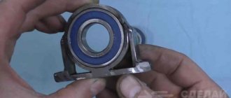
It is necessary to weld the jaws of the pliers to the inner race of the bearing with a diameter of 20 mm.
Then it is cut in half into half rings.
The result is a tool for gripping and pulling the hose onto fittings or pipes. It is suitable for a diameter of 20-25 mm.
Tool for replacing the ball joint VAZ 2110
There should not be any difficulties when replacing the support. The only thing that can overshadow the replacement procedure is the pressing out of the support pin cone from the steering knuckle. There is a special puller for this, but if the situation is not very advanced, then you can do without a puller. Although a set of pullers for dismantling steering rods and supports simply must be, if not in the trunk, then certainly in the garage.
To replace the support, we will need keys from a standard road set, the same mount, a new ball joint and a puller. The puller can be of several types, a universal puller can be used, this is not a problem, you can buy such a thing at any auto store, but when it is not at hand, it has a very noticeable effect on the work time.
Retaining Ring Puller
Nuts with screwed-in sharpened short pins are welded to the jaws of the pliers.
The edges of the latter need to be heated red-hot and hardened in oil.
This tool can be used to stretch and remove retaining springs.
You can also tighten the grinder discs.
Universal wrench
Strips are welded to one cheek of the pliers on the sides.
A nut and bolt are welded to their edge.
You need to weld a piece of strip to the head of the latter in order to rotate it by hand.
As a result, the bolt can be used to clamp the jaws of the pliers. This allows them to be used as a wrench. This tool will be especially useful if you need to unscrew a bolt with licked edges.
Useful tips
- Do not undertake restoration of the hinge if the pin is removed from it without disassembly; repair will not help such an assembly, but only replacement. The hole for the finger in the body must be smaller than the diameter of the ball in order to. If the liner wears out, the finger cannot fly out of the body, causing an accident.
- When restoring a hinge with your own hands, disassemble it completely and grind the ball of the finger, no matter how you intend to restore the assembly. Then the fruit of your work will not need replacement so soon. Even if you are planning to use an extruder for restoration, do not be too lazy to disassemble the hinge to see if the pin needs replacement. If you don't need it, then just polish his ball.
Greetings, dear subscribers and readers. Today in our issue of “crazy hands” I will tell you how to assemble a cold thermonuclear fusion installation at home from shit and sticks and replace the ball joints with non-original ones from Mitsubishi Karizma/Speystar. Why from Karizma? It's simple. Ball bearings from Mazda and Kia require turning the ball body or boring the seat of the levers. Ball joints from Renault Logan require grinding of the adapter sleeve because... the body is much narrower. And only ball ones require practically nothing from Karizma, just a little.
The work can be done in two ways. Homemade vanilla, using a Dremel, chisel and hammer, 400 grams (the more the better). Or harsh garage BDSM fucking, using entrenching tools in the form of a sledgehammer, a pry bar and a chisel. I did one lever this way, the other that way, so I’ll tell you about both methods.
Method number one (home): You will need a grinder (optional), a Dremel (engraver) with a flexible drive and cutting diamond or carborundum discs (required), as well as a small chisel and hammer (the bigger the better). 1) Remove the lever. We bring it home, clean it, wash it. We remove the boot from the ball, pick out the shit from the ball. 2) Saw off the ball finger at the root. If you don’t do this and knock the ball out by hitting your finger, the ball joint will disperse the blow in all directions and you won’t be able to knock out the ball this way. This is why you need a grinder. Actually, you can saw it off with a Dremel, which is exactly what I sawed with it. The question is time. 3) Using an awl or scriber, draw a line along the weld seam, along the border of the ball and lever. 4) Take a Dremel and cut along the drawn line. To begin with, it is better to take a large reinforced carborundum disc and work with it, then switch to a small diamond one. The diamond cutting surface gets washed out quickly and cuts only so-so. 5) When the Dremel disk is immersed a third into the weld seam, you need to take a chisel and, using it and a hammer, cut the groove to be cut. Those. make it wider so that the Dremel disk, God forbid, does not bite into it. It is better to cut towards the shoulder of the ball joint so as not to shred the lever. 6) When we decide that it has been sawed and cut enough, try hitting the ball joint with a hammer. It’s better to do this not by weight, it’s of little use. You need to put something inelastic, a piece of rail or channel for example. 7) At a certain moment we will see that the ball began to come out of the lever. We look at where the welding is interfering with it and cut it there. So over several cycles we slowly knock the ball out of the lever. The time for everything about everything is from an hour or more.
Bar bender
It is required to weld the halves of the pipe cut along the length, turned in one direction, to the jaws of the long-nose pliers.
This tool allows you to bend even rings and springs from wire.
Rotary pliers
The handles of the pliers are cut off.
Holes are drilled in the protrusions remaining from them and threads are cut.
A piece of square rod 10-20 mm long is welded to the cut handle. Holes are drilled in the extended edges. The handles are then screwed to the main part of the pliers.
The tool is now rotary.
Formwork
The use of old slate can significantly reduce wood consumption during the construction of formwork: instead of boards, material removed from the roof is used. Before starting work, the sheets are inspected and holes and cracks are sealed using sealant.
Dig a trench as wide as the thickness of the formwork and carefully level the walls. Fill the bottom with a 10 cm layer of sand or crushed stone and compact it. Along the entire perimeter of the trench, posts made of timber with a cross-section of at least 50 mm are driven in. They are placed at a distance equal to the length of the slate.
Pre-cut sheets are installed in the trench, placing them so that the posts are on the outside. They are fixed with self-tapping screws, screwing the fasteners not all the way, so that the fragile material does not crack.
A frame made of reinforcement is mounted in the trench. Wooden posts are additionally tied with bars. The space between the slate and the walls of the trench is filled with a mixture of clay and sand. Prepare cement mortar and fill the formwork.
Important! The composition should be poured in small portions, leveling with a shovel along the entire length of the trench. If you supply a large volume of cement, the structure will not hold up.
After the solution has hardened, the racks are dismantled.
1. The first step, of course, is to remove the wheel.
2. Next, using a metal brush, clean the ball joint mounts.
3. Treat all connections that will be removed (as shown in the photo) using WD-40 or similar thread penetrating fluid.
4. Take a “22” wrench and unscrew the nuts of the upper and lower ball joints by about one and a half to two turns.
5. Now install the special ball joint remover.
6. As a rule, in one step, it is possible to pull out two ball joints at once: the upper one “shoots off” first, and then the lower one. If for some reason the ball does not give in and remains in place, then using a steel drift and hammer, you can help it come out. The blows must be applied to the protrusion, which is on the steering knuckle.
7. When the ball joints of the VAZ 2107 have been pressed out, unscrew the fastening nut of the upper ball joint and remove the ball joint from the knuckle.
8. If the finger rotates, clamp the lever using a pry bar.
9. Unscrew the fastening of the ball joint to the upper arm.
10. Now you can remove the ball joint.
11. Next, you need to carefully clean the seat of the ball joint on the lever, while carefully looking at the lever to see if there is any damage or cracks on it.
12. Remove the sealing washer from the old ball joint and install it on the new ball joint.
13. Before installing the ball joint, it must be thoroughly lubricated; for this use ShRB-4, Litol-24 lubricant.
14. Install the boot with the washer.
15. Now you can tighten the ball to the lever. Install the ball into the fist and tighten the nut.
16. Unscrew the lower ball nut, almost always the pin starts to rotate, to avoid this, install the mounting between the knuckle and the brake shield, then make a lateral tension in the connection between the pin and the knuckle.
17. If it doesn’t help, install an adjustable wrench in the gap between the lower arm and the fist and use it to keep your finger from turning.
18. The nut is unscrewed, you can raise your fist upward. In the cut between the upper part of the fist and the lower arm, set the key to “22”, this will make further work more convenient.
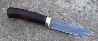
Marking compass
The hinge on the wire cutters or pliers needs to be drilled out.
The edges of the handles are then sharpened and their sharp edges are hardened in oil.
The disconnected halves are connected back, but with a bolt and a wing nut.
The result is a marking compass.
Recovery
- Emery or grinder.
- Extruder.
- An electric drill with a large chuck (so you can hold your finger in it to sand the ball with sandpaper).
- Metalwork yews.
- Welding machine (preferably semi-automatic).
- Compressor.
Restoration of supports can occur in two ways:
- Converting a non-separable hinge into a collapsible one, grinding the pin ball and replacing the liners.
- Repair by injecting softened plastic into the gap between the ball and the body using an extruder.
Of course, you shouldn’t buy equipment for a one-time repair, but you can quickly make a simple extruder with your own hands from an old brake master cylinder by attaching a lever to it to press the piston. You can heat it to soften the plastic with a torch or blowtorch.
End pliers for nails
A segment is cut out in the inner race of the bearing.
Instead, the jaws of the pliers are welded in. Next, the clip is cut in half, and the edges of the cuts are sharpened.
The result is end pliers for pulling out nails and cutting through wires.
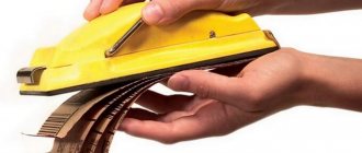
Holder for trimming pipes and rods with a grinder
This tool requires clamping pliers. A hole is drilled into them, into which a machined pin with a bushing and a spring is inserted.
The edge of the finger is welded into the pliers.
A strip is welded to the bushing on the pin. A hole is made in it to screw the angle grinder. For reliability, the body of the angle grinder is additionally attracted to the strip with a clamp.
Such a tool can be used to fix the grinder when cutting pipes, fittings, and rods. Thanks to him, the cuts will be smooth. This will help if you don't have a miter saw.
Ball joints: how they work and how to change them
Ball joints: how they work and how to change them
How do ball joints work in a suspension?
Why are they integrated into the suspension arms, why do they wear out and how difficult is it to change them on a modern car? Let's look into this issue in every detail.
Why do you need a ball joint?
A ball joint is, structurally, nothing more than a hinge with which the wheel hub is attached to the suspension arm. Its main task is to give the wheels freedom of movement in the horizontal plane and exclude it in the vertical. In general, ball joints are used not only in hub supports - they can be found in camber arms, in the steering linkage, and even in fastening the hood gas stops.
But until a certain time, instead of movable ball joints on swivel wheels, a kingpin joint was used - heavy, requiring periodic lubrication, and most importantly, providing the wheel with only freedom of rotation along one axis, which negatively affected handling.
The designers understood that the ball joint would take every hit from the road, so the wear and tear would become colossal. There was no point in making a part with particularly durable diamond coating, so it was deliberately turned into almost a consumable. So that if something happens, you can easily unscrew a couple of bolts and a nut and replace it with a new one.
Ball design
Initially, the support was a housing in which a ball pin was installed and pressed through a metal plate with a spring, and covered with a boot on top. To prevent the pin from wearing out after two days, they added lubricant and instructed everyone involved in maintenance to regularly check and replace the lubricant in the housing by pressing it through the oiler.
Then came the era of plastic, and the spring disappeared from the design. The ball part of the finger was placed in a hemisphere formed by liners made of the above material. Since then, essentially, the design has not changed, the only thing is that the plastic was replaced with more wear-resistant nylon.
Ball joints were divided into serviceable and non-serviceable, that is, with oilers and the possibility of disassembly and without, respectively. But the closer to the present decade, the less collapsible supports were used. Ball joints with grease nipples for storing lubricant remain an echo of the era, but maintenance-free bearings have long been installed on almost all machines.
How many ball joints are there in the suspension?
It all comes down to the type of suspension. The simplest MacPhersons have two balls - they are located at the bottom. The more levers, the more balls. On double wishbones there are upper and lower ball joints, and on the most complex suspensions, mainly for Volkswagen and Audi, there can be five ball joints on one side.
Fastening to the lever
Now the entire classification comes down not to the type of design of the ball itself, but to the method of its installation - replacement costs greatly depend on this. The simplest and most peaceful design for the car owner is the one with the support housing attached to the suspension arm using bolts, nuts or rivets. In this case, disconnecting the worn ball from the lever will not be difficult. It would seem that the design was brought to perfection, but since the late 1990s, engineers gradually began to abandon it in favor of a support integrated into the suspension arm.
THERE IS AN OPINION THAT THIS DESIGN WAS LOBBYED BY MARKETOLISTS WHO WANTED TO INCREASE THE PROFITABILITY OF SALES OF SPARE PARTS, BECAUSE NOW WHEN THE BALL IS WEARED, YOU NEED TO CHANGE THE LEVER ASSEMBLY, EVEN IF THE LEVER ITSELF IS OK. BUT IN ACTUALITY ALL THIS HAS A PURELY ENGINEERING SENSE: A SUSPENSION WITH BALL JOINTS INTEGRATED INTO THE ARMS IS SIMPLY EASIER THAN DISASSEMBLY.
There is a compromise design in which there are no fastening elements to the lever, but there is a fixation element - a locking ring. In this case, the support is simply pressed into the lever (for example, Zafira C and Jeep Patriot). To replace it, you will have to use a press or another forceful method (more on this below).
Fasteners to the steering knuckle
We have considered the main types of fastening to the lever; now let’s turn our attention to fixing the ball joint to the steering knuckle, provided that the support is on the lever. There are only two options: the support pin can be connected and secured with a nut, which is either cottered, or a self-locking nut with an internal locking ring is used. An alternative fastening option is a pinch bolt, as, for example, in the Hyundai Santa Fe since 2006. The latter option is more troublesome, since the bolt, in practice, is prone to souring.
IT ALSO OFTEN HAPPENS THAT IN ORDER TO OPEN THE ENDS OF THE FIST BRACKET IN WHICH THE SUPPORT FINGER IS FIXED, IT IS NECESSARY TO USE A SPECIAL WEDGE, WHICH IS OFTEN SIMPLY NOT AVAILABLE. A PROBLEM MAY APPEAR WHERE YOU DON'T EXPECT IT.
Take the Audi A6 C7, for example: there is a wonderful design of the front multi-link suspension, in which the ball joints of the upper arms are connected to the steering knuckle and secured with one long pinch bolt, which very often sticks so much that it is impossible to remove it. Neither heating the fist (it is made of an aluminum alloy), nor cooling the bolt, nor even applying five or even ten tons on a hydraulic press will budge this ill-fated bolt even a millimeter. And, as often happens in this case, the owner finds out that his wallet is empty by another 400–500 dollars - this is the average price for a new steering knuckle for the A6 C7.
Clamp pliers
You will need to cut the outer race of the large bearing in half.
The halves are joined, and the nuts on the bolt are welded to them.
Then a handle from a bent square is welded to each of them.
Between the handles you need to weld hooks for the spring and tighten it. The result is a quick-release locksmith clamp, which can also be used as pliers.
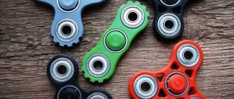
Cool DIY machine made from Bearing!
I'll show you what can be made from a bearing and old metal scraps, yet another homemade product exceeded all my expectations.
Products for inventors Link to the store.
The conductor should be an ideal shape, like a snail's curl, an even circle with an exit, like mosquito coils, only there are fewer rings. And your jig is angled and oval, so the curls are ovoid. Try to make another conductor, from the sole under the railway rails, where the nails are driven into the sleepers. Just make the jig in the shape of a drop with a curved tail, and it’s easier to cut, and smooth shapes look better, even if there is only one curl.
Source