Autonomous operation of all kinds of devices, from mobile gadgets to personal electric vehicles, is ensured by batteries. Taking into account the required capacity and voltage values, they are combined into batteries. The key characteristics of the battery - capacity, voltage, weight, charge replenishment time, permissible temperature conditions - depend on the type of chemistry used.
Lithium-ion batteries are successfully used to autonomously power modern equipment. They have a long cyclic life, low self-discharge, a wide temperature range and a solid specific capacity. The cathode of such cells is made of lithium derivatives, and the charge is carried by Li ions. Next, we will take a closer look at the design of Li-ion batteries and the principle of their operation.
How does a lithium-ion battery work?
The design of a lithium-ion battery is based on two components: an anode made of porous carbon on copper foil, and a cathode made of lithium oxide on aluminum foil. They are separated by a porous polypropylene separator, richly impregnated with electrolyte, which acts as a conductor. The system is housed in a sealed housing. The electrodes are connected to current collectors. Some batteries additionally have a safety valve to relieve internal pressure.
Plates of copper and aluminum, lubricated with an electrolyte and separated by a porous layer, are usually rolled up. The result is a cylindrical element. With another method of laying plates, products are obtained in the form of prisms and packages. The composition of the cathode varies: LiMn2O4, LiFePO4, LiCoO2, LiMnO2, LiMnRON, LiC6, LiNiO2, etc.
Types of Li-ion batteries
Depending on the cathode material used, lithium cells are:
- Lithium-manganese (LiMn2O4, LNO). They have lower internal resistance, high power and moderate capacity - 100–150 Wh/kg. Standard charge and discharge currents are up to 1C, but there are models with a C-rating for charging up to 3C and a C-rating for discharge up to 10C, and in pulse mode - up to 50C. Resource – about 500 cycles. Such drives are used in power tools, power units, and medical equipment.
- Lithium-cobalt (LiCoO2, LCO). They have high energy intensity (150–200 Wh/kg), but are inferior to analogues in thermal stability and service life (500–1000 cycles). Charge and discharge currents for such elements should not exceed 1C. Cobalt-based energy storage devices are becoming less common, but are still used in mobile phones, digital cameras, and laptops.
- Lithium-nickel-manganese-cobalt oxide (NMC, NCM). Provide high power and capacity - 150–220 Wh/kg, withstand 1000–2000 cycles. Standard charge and discharge currents are 1C. Used in medical and industrial equipment, electric bicycles and other types of electric transport.
- Lithium Nickel Cobalt Aluminum Oxide (NCA). They are characterized by high specific energy intensity - 200–260 Wh/kg. They have a service life of about 500 cycles, charging currents of 0.7C and discharge currents of 1C. Provide autonomous power supply for industrial and medical equipment, electric power units and other devices requiring high capacity.
- Lithium iron phosphate (LFP, LiFePO4). They are distinguished by a long service life (more than 2000 cycles), thermal and chemical stability, high operational safety and low internal resistance. Their specific energy intensity is 90–120 Wh/kg, charging current is 1C, discharge current is up to 25C. Such batteries are used in devices for which battery endurance, the ability to operate in cold weather and withstand high load currents are important.
- Lithium titanate (LiTi). They are characterized by a low nominal voltage (2.4 V) and a specific energy intensity of 70–80 Wh/kg, but they charge quickly, have a wide temperature range and a service life of 3000–7000 cycles. Rated charging currents are 1C, maximum – 5C. Permissible discharge currents are 10C, and for pulse charging - 30C. Lithium titanate cells are considered the safest. They are used in street lighting, UPS, and electric vehicles.
How does a lithium battery work?
The principle of operation of Li-ion batteries is identical for elements of all types, regardless of the cathode material. When voltage is applied to the electrodes - “plus” to lithium oxide and “minus” to graphite - positively charged lithium ions are detached from the oxide molecules and transferred to the carbon plate. As a result, an oxidation reaction occurs and the battery is charged.
When a lithium battery operates under load, the reverse process occurs. The Li+ ions return to the lithium oxide plate to their standard state. A graphite plate on a copper foil becomes a “minus”, and a lithium oxide on an aluminum foil becomes a “plus”.
Control/indication chips
The basis of the line of “battery microcircuits” of any manufacturer is precisely the battery charger microcircuits (Battery Chargers IC), which were discussed above. But many manufacturers supplement the range with “related” microcircuits, which include battery status monitoring microcircuits (Battery Status Monitor) and battery charge level indicating microcircuits (Battery Gas Gauge). In the STMicroelectronics nomenclature, both of these roles are performed by STC3100 and STC3105 . The STC3105 connection diagram is shown in Figure 6.
Rice. 6. STC3105 connection diagram
From a functional point of view, the microcircuit periodically measures the voltage values at the output of the microcircuit and the current flowing through it. The received and processed data is transmitted to the microcontroller via the I2C channel. These microcircuits, on the one hand, can be an effective addition to simple charging microcircuits in applications where there is no point in complicating the charging procedure itself, but it may be useful to expand the control functions over the process. On the other hand, the I2C interface assumes the presence of a microcontroller that must receive data and, as a result, make some decision based on it. But in this case, the decision begs to use smart chips STBC21 and STw4102, which already implement some monitoring functions.
Features of charging Li-ion cells
Lithium-ion batteries are sensitive to overcharging. When overcharged, lithium metal is deposited on the anode surface. It appears as a fine mossy residue and is capable of reacting with the electrolyte. Oxygen is actively released at the cathode during recharging. Externally, this can manifest itself in the form of intense heating, increased pressure and depressurization of the element.
Li-ion batteries are charged in 2 stages:
- With a stable current value of 0.2C–1C up to the voltage recommended by the manufacturer, usually 4.1–4.2 V. This stage lasts about 40 minutes.
- At constant voltage. The charging process is completed when the charging current decreases to 3% of the initial value.
Charging occurs faster in pulse mode. But to extend the service life of lithium cells, it is recommended to charge them with a current whose nominal value is 50% of the capacity value, i.e. 0.5C.
CC/CV controllers
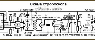
In addition to functionally complete battery charging chips, STMicroelectronics offers a family of CC/CV controller chips, in particular the TSM101x . These chips include a voltage reference and two operational amplifiers, usually with a combined output. Figure 7 shows a fragment of a network charger circuit for a lithium battery using a TSM1012 . The first operational amplifier (CV - Constant Voltage) implements a stabilized direct voltage circuit, and the second (CC - Constant Current) implements a stabilized direct current circuit. The remaining components are a typical switching power supply wiring and master circuits.
Rice. 7. Mains charger on CC/CV controller TSM1012
Recall that the charge cycle of a lithium battery consists of two phases in which the device acts as a constant current source and one phase in which the device acts as a constant voltage source. Of course, designing a charger based on universal “bricks” is a more troublesome and time-consuming task than using specialized circuits. However, in this case it becomes possible to create devices in which some parameters are at a significantly different quality level. For example, work [5] presents a number of solutions that can significantly reduce the power consumption of a network charger in idle mode. Calculations are given according to which a typical solution provides a total power consumption value of 440 mW. Initial optimization of the circuit using the TMS1011 results in a value of 140 mW, and further optimization of the circuit using the TMS1012 controller provides a further reduction in power to 104 mW. Of course, in most cases you can get by with standard solutions that do not give record-breaking, but quite acceptable indicators. However, it is worth keeping in mind the fact that the product line contains components that allow, if necessary, to develop a device with “elite” values of individual parameters.
Lithium battery protection
Lithium-based batteries are protected from short circuits within the system, for example, using a 2-layer separator. One of its layers is made not from polypropylene, but from an analogue of polyethylene. If there is a risk of a short circuit, for example, if lithium dendrites grow towards the cathode, the protective layer locally heats up, partially melts, becomes impenetrable and blocks subsequent dendritic growth.
To protect against overcharge and deep discharge, energy storage devices are equipped with special limiters - current and voltage protection boards. They do not allow the voltage to go beyond the recommended range and, in critical situations, automatically disconnect the element from the power supply or load.
Therefore, for the safe operation of cells and batteries, it is important to use BMS boards. Otherwise, there is a high risk of damage to the batteries and their premature failure. Such a charge-discharge process controller can be installed on both individual batteries and a battery assembled from them.
Settings recommendations
- After the first launch of the program, a special screen will appear.
- You have to press spacebar. This is how the user ends up in the main menu.
- Press F1, and then select Configure.
- Next, you need to click the “number of Axis” item. Use the Enter key.
- All that remains is to enter the amount of soybeans that you plan to use. In this case, we have one motor, so we click on number 1.
- To continue, use Enter. We will need the F1 key again, after using it in the Configure menu, select Configure Axis. Then press the space bar twice.
Drive Type - this is the tab we need, we reach it by numerous Tab presses. The down arrow helps you get to the Type item. We need a cell called Scale. Next, we determine how many steps the engine takes during just one revolution. To do this, just know the part number. Then it will be easy to understand how many degrees it rotates in just one step. Next, the number of degrees is divided into one step. This is how we calculate the number of steps.
The rest of the settings can be left as is. The number obtained in the Scale cell is simply copied to the same cell, but on another computer. The value 20 should be assigned to the Acceleration cell. The default value in this area is 2000, but it is too high for the system being built. The initial level is 20, and the maximum is 175. Next, all that remains is to press TAB until the user reaches the Last Phase item. Here you need to put the number 4. Next, press Tab until we reach the row of X’s, the first in the list. The first four lines should contain the following items:
1000XXXXXXXX 0100XXXXXXXX 0010XXXXXXXX 0001XXXXXXXX
No changes need to be made to the remaining cells. Just select OK. That's it, the program is configured to work with the computer and the actuators themselves.