It is hardly possible to meet a motorist who has not encountered the problem of a dead battery . In such cases, you cannot do without a reliable power source that uses composite transistors. If you don’t have the necessary device at hand, we’ll tell you how to make a charger from an uninterruptible power supply with your own hands without spending a lot of money. Finding this device is not difficult - it may be a non-working or unnecessary UPS that has long been replaced by a newer model. Why did you choose this product? It's simple - the uninterruptible power supply contains the necessary elements of the electrical circuit. If the UPS is not working, then the most important part for us in it is the transformer.
You can make a charger either from an old and non-working device, or from a working one, if you do not plan to use it further for its main purpose. This operation is relatively simple if you have knowledge related to electronics.
Otherwise, we advise you to familiarize yourself with this issue first.
Safety regulations
Safety precautions in our case are no different from those with other electrical appliances . It is strictly forbidden to disassemble devices connected to the network, as well as to carry out any additional manipulations with them. Do not forget that if a malfunction is detected, electrical equipment must be repaired or replaced as soon as possible.
Also, to assemble the charger, you will need certain knowledge in the field of electronics in order to correctly place certain elements of the circuit.
Is it possible to connect a car battery to a UPS?
Opinions on this matter are twofold, but radically different. Often, according to various reviews, car batteries cope with this task quite well and work stably. The main problem: gases that will be released when charging the battery and overheating of the transformer and power switches. The last problem can be at least partially eliminated by using additional fans, etc. But no one can escape from the gases when charging. When charging, not only explosive hydrogen is released, but also other gases, and these are far from vitamins. If an inverter from an uninterruptible power supply is used in a car, then this question disappears by itself. It is also important to remember that the battery is charged from the mains with a fairly small current and the charging process can take a long time. You can safely avoid this if you charge the battery separately from the UPS, for example, for these purposes you can use a homemade charger from a computer power supply. Whether to use a car battery in UPS is up to you to decide.
Scheme
Another option for making a charger yourself. This method differs little from the previous one, but there are diagrams here - this is very convenient for working with electrical devices. Such a device includes powerful composite transistors KT947, KT827. The dotted lines shown in the diagram are additional capacitors. Diodes with transistors can be structurally placed on a common large radiator; insulating gaskets are not required.
If there is no transformer with a 16-volt center tap, you can use a circuit that includes a rectifier bridge. Resistor R1 is needed to protect the composite transistor from short circuits.
If you assemble devices using these circuits, the output voltage will be adjusted from 0 to 15 V, and the maximum charging current will be up to 10 A.
Having converted the uninterruptible power supply to an inverter, at the output we get:
- Voltage regulator;
- Charger;
- and of course the inverter.
After our modification, if the uninterruptible power supply is 300 W, then you can load it with 200 W. Of course, the more powerful the uninterruptible power supply, the more you can increase the load on it.
In some UPS systems there are places where you can further increase the power. These places are called transistor switches. As soon as you solder them, the power of the uninterruptible power supply will increase.
Manufacturers sometimes do not solder such transistors in order to reduce the cost of the product. Transistors need the same rating as those installed.
You should also increase the cross-section of the wires from the board connector to the alligator battery.
From the secondary winding transformer to the board terminals,
you need to add one more wire in parallel to increase the cross-section.
The transformer had to be pried apart a little to get to the output of the secondary winding. There are three of these wires coming out.
To prevent the uninterruptible power supply from beeping every minute, we must remove the round beeper.
Next, in the case, I drilled a hole for the fan using a plaster or wood bit and positioned it so that it would blow on the switches of the transistors and radiators.
On the back wall I removed unnecessary connectors and left a hole for them to allow air to escape.
From these terminals we find two 220 volt power wires - the output from the board after the converter and we bring these wires out, we fix our socket.
Our uninterruptible power supply inverter is almost ready. To monitor the battery discharge of a car battery, you can build in a digital voltmeter. Just in case, I also connected a temperature sensor to monitor the temperature on the transistor switches. I attached the thermocouple from the multimeter to the radiator of the field operator’s transistor.
An important point: the inverter from an uninterruptible power supply must have a cold start - this is a function when it can be turned on without external power from a 220-volt household outlet. In some models, the cold start button is pressed twice at different intervals.
That's all the changes. You can take such an inverter with you on a trip - on a picnic, fishing, at home - through it you can connect lamps, a laptop, charge phones, flashlights, in the country and in the countryside - connect an incubator, greenhouse lighting, etc., but no more 70% of the power of our product.
For lighting it is better to use diode lamps; they have little draw and burn brightly. I also connected an 80 W soldering iron, even the TV works without problems.
Alex Oleynik
In everyday life, sometimes there is an urgent need for uninterrupted power supply to various devices. This could be emergency lighting, incubators, aquarium equipment, or a simple amplifier with which the company went outdoors. Modern budget computer uninterruptible power supplies can operate for no more than half an hour from autonomous power supply, and those that can and are specifically designed for this cost completely different money. Car inverters do not always output a frequency of 50 Hz. If you need autonomy for several hours, then the thought immediately comes to mind whether it is possible to power the UPS from an ordinary car battery. We will try to answer this question today; we will make an inverter from a UPS with our own hands.
What kind of batteries are used in uninterruptible power supplies?
The UPS uses sealed (maintenance-free), mainly 12-volt batteries with a capacity of 5 to 250 Ah with output terminals (knife) Faston 187/250 (F2). The UPS uses the following types of batteries;
- with AGM technology;
- gel batteries.
- nickel-cadmium.
Batteries for UPS are produced by brands such as;
- IPPON - UK;
- Delta - China;
- Energy - Russia;
- CSB - Taiwan;
- BB Battery - Hong Kong;
- Fiamm - Italy;
- Leoch - China;
- C&D Technologies - USA;
- Yuasa - Japan;
- Sonnenschein - Germany;
- SVEN - China;
- Tudor - Portugal.
All UPS battery models are sealed and maintenance-free. The body material used is ABS (acrylonitrile butadiene styrene) plastic, which is resistant to mechanical and chemical influences and is a non-flammable material. The batteries for the UPS are located both inside the UPS and outside, depending on the power of the UPS. One of the common battery sizes for internal installation in a UPS is 151x65x94 (mm). Table 1 shows battery dimensions depending on capacity.
With a high output power of the UPS, high-capacity batteries are required, up to 250 Ah. Given their size and weight, they are installed externally. Table 2 shows the characteristics of some batteries for high-capacity sources.
| Picture | Name | Weight, kg) | Manufacturer country | Capacity (A/h) | Dimensions (mm) | Voltage | Type |
| SB HRL 12280W | 28,50 | Taiwan | 70 | 261x168x210 | 12 | AGM | |
| Delta HRL 12-100 | 33 | China | 100 | 330x171x215 | 12 | AGM | |
| LogicPower SILVER LP-MG 12-250 | 69 | Ukraine | 250 | 522x268x220 | 12 | AGM | |
| Fiamm 12FGL150 | 46.2 | Italy | 150 | 483x171x220 | 12 | AGM |
Table 2. Characteristics of powerful batteries.
Before the end of the warranty period of the battery or when the uninterruptible power supply begins to malfunction, it is necessary to check its energy capacity, which shows the ability to discharge in constant power mode for a short time (up to 15 minutes).
The UPS design provides for independent battery replacement. When replacing, you must take precautions when working with batteries. To maintain the performance characteristics of the UPS, the same type of drive (type and capacity) must be used when replacing.
Old uninterruptible power supply
Our valiant organization has a workshop that periodically assembles its crafts. And they go to installations like “drill 2 small holes, and the nearest outlet is 3 kilometers away” very often. Naturally, they have to carry a hefty 3 kilowatt generator. Deere decided to buy a 12-220V converter (inverter), but it costs from 1500 rubles, which is much more money spent on gasoline for the generator in a year. and then the thought came to us, what do we need a hill of uninterruptible power supply systems?
The first uninterruptible power supply that came across did not survive the test runs. Sintered in 5 minutes(, eternal memory to him.
The most powerful victim was quickly chosen, an Ippon UPS with 800 volt-amperes output.
The transformer does not hold up without a battery; I had to screw it tightly with self-tapping screws.
It was decided to eliminate the overheating problem by forced air cooling. Several holes had to be made in the front part.
The mesh is metal, glued with a heat gun.
Of course, it was also necessary to glue a fine dust mesh, but this came to mind after assembly. I'm too lazy to take it back apart, I'll glue it while cleaning.
All connectors on the back
Removed due to their complete uselessness. The mesh is also glued.
A couple of fans were needed. The 8cm Chinese fit perfectly. The insulation is laid in places where the fans do not come into close contact with the housing.
The 12-volt wires are extended with long wires with alligator clips to connect to the car battery. The holes from the telephone connectors in the case of the uninterruptible power supply also came in handy. The USB was accidentally torn off.
An outlet was installed on the side of the UPS)
That's almost all
The beeper was also pulled out, he got it, honestly. This is how the beautiful 12-220V inverter turned out:
Quietly pulls a small hammer drill at 550W, a drill at 600, and does not heat up (stupidly cannot keep up with the powerful air flow)
The entry was published in the Alterations section. Bookmark the permalink.
sdelalsam.com
UPS charger with dimmer
I made chargers from old uninterruptible power supplies several times, but they were completely ugly, quick-made crafts, assembled on a board, without adjustment and even without a fuse. One of them was even published on homemade
Of course, somewhere in the forest, in a village 100 km from the city, a dead battery, if absolutely necessary, you can try to charge it from anything, but for constant use you need a good and safe design.
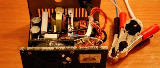
We disassemble the uninterruptible power supply and remove everything unnecessary. We leave the mains connector with a fuse, an output socket (still useful), a transformer, and a switch.
You will also need a powerful diode bridge with a radiator, a 4700 uF 35V capacitor, a cooler from a computer (but this is not necessary), a microammeter (I got it from an old cassette player), a shunt of about 0.3 Ohm and a dimmer. The most common dimmer, used for adjusting light in rooms, is suitable for 300 watts.
First you need to check the transformer. We find the winding with the highest resistance. This was most likely the output winding, with a voltage of 220V.
Now it will be the entrance. We apply voltage to it from the outlet and measure how much will be at the output.
It turned out to be 14.2V. alternating current. After rectification, the filter capacitor will produce about 19V.
We also disassemble the dimer, we only need its electronic filling with a regulator.
Well, then everything is simple. Using corners and screws with nuts, we secure all these spare parts in the body and connect all the above spare parts. There is no particular point in providing a wiring diagram, because there is nothing complicated in it.
The socket, which used to be the output of the uninterruptible power supply, is soldered directly to the network connector, and now simply serves as an extension cord.
The dimer is connected to the mains wire, in series with the mains switch, and regulates the mains voltage at the transformer input.
The output of the transformer is connected with its terminals to a diode bridge, which has the corresponding marking:
The positive, brown wire from the diode motor is soldered to a shunt assembled from three parallel-connected ceramic resistors with a resistance of 1 (one) Ohm. The result is 0.33 Ohm. Resistor power 5 watts. From the output of the shunt, the brown wire goes to the “plus” of the battery.
The microammeter wires are soldered directly to the shunt terminals. The microammeter itself is fixed to the plastic front panel using hot-melt adhesive. The holes in the plastic panel for the microammeter and the dimmer knob are made with a regular knife. The regulator handle is also attached with the same hot glue.
The battery is connected with special collet terminals purchased at a car store for the occasion.
Source
Do you have an old uninterruptible power supply? Then we go to you.
Our valiant organization has a workshop that periodically assembles its crafts. And they go to installations like “drill 2 small holes, and the nearest outlet is 3 kilometers away” very often. Naturally, they have to carry a hefty 3 kilowatt generator. Deere decided to buy a 12-220V converter, but it costs from 1500 rubles, which is much more money spent on gasoline for the generator in a year. and then the thought came to us, what do we need a hill of uninterruptible power supply systems?
———————————————
The first uninterruptible power supply that came across did not survive the test runs. Sintered in 5 minutes(, eternal memory to him.
The most powerful victim was quickly chosen, an Ippon UPS with 800 volt-amperes output.
The transformer does not hold up without a battery, so I had to screw it tightly with self-tapping screws.
It was decided to eliminate the overheating problem by forced air cooling.
Several holes had to be made in the front part.
The mesh is metal, glued with a heat gun.
Of course, it was also necessary to glue a fine dust mesh, but this came to mind after assembly. I'm too lazy to take it back apart, I'll glue it while cleaning.
All connectors on the back
Removed due to their complete uselessness. The mesh is also glued.
I needed a couple of fans.
The 8cm Chinese fit perfectly. The insulation is laid in places where the fans do not come into close contact with the housing.
The 12-volt wires are extended with long wires with alligator clips to connect to the car battery. The holes from the telephone connectors in the uninterruptible power supply also came in handy. The USB was accidentally torn off.
There is a socket installed on the side)
that's almost all
The beeper was also pulled out, he got it, honestly. This is how handsome the guy turned out:
Quietly pulls a small hammer drill at 550W, a drill at 600, and does not heat up (stupidly cannot keep up with the powerful air flow)
nnm.me
Rules for first charging and further use
For reliable operation of the battery during the warranty period, the manufacturer indicates restrictive data on the label;
- Rechargeable - rechargeable.
- Do not recharge - do not recharge (not charging).
- Initial current ХХ.Х А — charging current (no more).
- Floating (Standby) use XX V. - the maximum voltage at which the battery can remain for a long time (buffer mode).
- Cycle use - maximum voltage in cyclic mode (charge-discharge).
- Risk of fire, explosion, or burns - risk (danger) of fire, explosion or burn.
- Do not short circuit the battery - do not short-circuit the battery.
- Do not disassemble, heat above 40 °C or incinerate - do not disassemble, heat above 40 °C or burn.
- Recharge after use - recharge after use.
Figure 2 shows an example of a label (stencil) on a UPS battery.
The operating mode indicated on the case of your drive must be maintained at all times. A working uninterruptible power supply supports this mode. To check the functionality of the UPS battery charger, you need to disassemble the unit and use a multimeter to measure the voltage at the battery terminals (without disconnecting from the network). It should be (Floating use) 13–14 V. If it is less, then most likely the charging control circuit of the unit is faulty and it was not charging. Let's look at how to properly charge it yourself and check its performance.
Before installing a new battery, it must be recharged (several hours), as it loses charge during storage (from the date of manufacture to the date of sale). If the charge is lost by 25%, the battery must be recharged with a simple charger with a voltage of no more than 14 V, and in case of a deeper discharge (battery voltage below 10 V), automatic (smart) chargers with three charging stages must be used. The voltage at the terminals is measured with a multimeter.
Important. All switching must be done with the mains voltage turned off.
Before using a new battery, it is necessary to carry out a control and training cycle for the battery (discharge-charge). For this it is necessary;
- Install, secure and connect the battery (red +, black -).
- Disconnect the load from the UPS.
- Turn on the uninterruptible power supply to the network. Further restoration of the capacity will be carried out in normal mode, by the internal UPS circuit under the control of the controller.
- Turn off the UPS after a few hours (up to 24 hours).
- Connect the load to the UPS. You can turn on an equivalent load - an electric light bulb, an electric stove, etc., but the power is not greater than the power of the UPS.
- Disconnect from the network and turn on the UPS. When the storage is low, the UPS will shut down and the green indicator will flash and beep rapidly.
- Repeat the cycle 2 or 3 times.
- If there are no failures, connect the standard load, and you can use the device.
Power supply, UPS charger
Having considered all possible options for the future power supply, I ordered the necessary components from China and prepared the case so as not to waste time. I moved the transformer from its original place and secured it to the bottom with four M4 screws, where the trans stood. installed a radiator for the future diode bridge. I also cut a hole for the fan in the back of the case.
About a month later, a pulsed step-down converter for XL4016 12A 0-32V arrived, here is a link to it. Why did I bother to take a photo before remaking the converter, so I’ll explain what I did.
Instead of native trimming resistors, Soviet resistors were installed. For the voltage regulator, the resistor is set to 4.7 kOhm, I will bring it out with two wires to the front panel. This rating makes it possible to regulate the voltage within 1.2V-18.5V. For the current regulator, I installed a 1 kOhm variable resistor, and added a 25 kOhm resistor along the positive wire, which makes it possible to regulate the current within 0-10A. Also, instead of the block, I soldered wires, wires 0.75 mm square. twisted in pairs to increase the cross-section.
Another month later, literally yesterday, the rest of the components arrived and I got to work. Again, there are no photos of the process, so I’ll go through the finished device. There were two regulators on the front panel: current and voltage. A 10A type 91C4 ammeter, an electronic voltmeter and terminal blocks left over from the previous regulated power supply were installed. I also brought out a voltage stabilization indicator LED from the board.
In the rear part, an XL4016 converter board is installed on the partition, a KBPC5010 diode bridge is installed on the radiator, and a 35V 4700 uF capacitor is glued to the case. The capacitor is needed to filter the mains voltage, after the bridge with it the voltage was 22V. To power the fan and voltmeter, I used an additional winding from a transformer and installed a diode bridge with a 2200 uF capacitor. After the 25V diode bridge, this voltage is suitable for powering a voltmeter, but this is too much for powering a fan, so the fan will be powered through two parallel 470 Ohm 2 W resistors. The bridge with the condenser was secured with a canopy. By the way, to protect against any cases
