We talked about how to independently calculate a wind generator in one of our previous materials. Today we will present to your attention models of wind turbines built by users of our portal. We will also share useful tips that will help you assemble the installation and avoid mistakes. Building a wind generator with your own hands is a difficult task. Not every (even experienced) practitioner can cope with its solution accurately. However, any error detected in time can be corrected. That's what the master needs his head and hands for.
The article addresses the following questions:
- From what materials and according to what drawings can wind generator blades be made?
- Assembly procedure for the axial generator.
- Is it worth converting a car generator to a wind turbine and how to do it correctly.
- How to protect a wind generator from a storm.
- At what height should the wind generator be installed?
Manufacturing of blades
If you do not yet have experience in making screws for your home wind turbine yourself, we recommend that you do not look for complex solutions, but use a simple method that has proven its effectiveness in practice. It involves making blades from ordinary PVC sewer pipes. This method is simple, accessible and cheap.
Mikhail26 FORUMHOUSE user
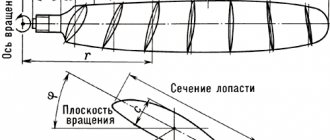
Now about the blades: I made them from a 160-gauge red sewer pipe with a foamed inner layer. I did it according to the calculation shown in the photo.
The “red” pipe was not mentioned by the user by chance. It is this material that holds its shape better, is resistant to temperature changes and lasts longer (compared to gray PVC pipes).
Most often, pipes with a diameter of 160 to 200 mm are used in home wind energy. This is where you should start your experiments.
The shape and configuration of the blades are parameters that depend on the diameter of the pipe from which they are made, on the diameter of the wind wheel, on the speed of the rotor and other design characteristics. In order not to bother yourself with aerodynamic calculations, you can use a ready-made table, which its author posted in the corresponding topic on our portal. It will allow you to determine the geometry of the blades by substituting your own values (pipe diameter, propeller speed, etc.) into the calculation table.
Mikhail26
I got used to sawing with a jigsaw. It turns out really quickly and efficiently. Note: be sure to place a large free stroke of the file on the jigsaw so that the file does not bite or break.
Wind generator with vertical axis of rotation
In wind generators of this type, the rotating axis of the generator is located vertically relative to the surface of the earth.
Over the years of using devices of this type, various designs have appeared that are combined into groups, these are:
With a Darrieus rotor - the units are equipped with two or three blades curved in the shape of an oval.
The positive features of this design include:
- Independent orientation in relation to air flows;
- Convenient installation maintenance.
- Simplicity of the unit diagram.
The negative ones include:
- There is no possibility to independently spin the blades;
- Significant load on structural elements;
- The blades must be identical and correspond to the specified profile;
- Increased noise level during operation.
- With a Savonius rotor - the units are equipped with blades in the form of cylindrical surfaces.
The advantages of this group are:
- Insignificant wind flows are required to start operation;
- Ability to quickly gain torque;
- Reliability of the design;
- Low cost.
The disadvantages include:
- Low efficiency of devices in this group.
Devices with a Savonius rotor are used when installing combined wind generators; they are used to accelerate units with a Darrieus rotor.
With vertical-axis rotor designs - the units of this group have blades that resemble the shape of an airplane wing and are located vertically, the rotor axis is parallel to the shaft.
In appearance, the units of this group are similar to devices with a Darrieus rotor.
The positive qualities of the devices include:
- Ease of manufacture;
- Ability to quickly increase rotation speed;
- Low noise level.
- Reliability in operation.
- With a helicoidal rotor - units of this group are a more developed version of devices with a vertical axial rotor. The blades have a helicoidal curve shape.
Positive traits:
- Lower loads on structural elements;
- Quick set of rotation speed.
Flaws:
- Increased noise level;
- High price.
- Multi-blade rotor - units of this type are based on a vertical-axis design with an additional outer ring of fixed blades.
Advantages of units of this group:
- Higher efficiency of installations;
- Sensitivity to wind currents.
Flaws:
- High price;
- Increased noise level.
Sun
In the first position is the simplest one, most often called the Savonius rotor. In fact, it was invented in 1924 in the USSR by J. A. and A. A. Voronin, and the Finnish industrialist Sigurd Savonius shamelessly appropriated the invention, ignoring the Soviet copyright certificate, and began serial production. But the introduction of an invention in the future means a lot, so in order not to stir up the past and not disturb the ashes of the deceased, we will call this windmill a Voronin-Savonius rotor, or for short, VS.
The aircraft is good for the home-made man, except for the “locomotive” KIEV at 10-18%. However, in the USSR they worked a lot on it, and there are developments. Below we will look at an improved design, not much more complex, but according to KIEV, it gives bladers a head start.
Note: the two-blade aircraft does not spin, but jerks jerkily; The 4-blade is only slightly smoother, but loses a lot in KIEV. To improve, 4-trough blades are most often divided into two floors - a pair of blades below, and another pair, rotated 90 degrees horizontally, above them. KIEV is preserved, and the lateral loads on the mechanics weaken, but the bending loads increase somewhat, and with a wind of more than 25 m/s such an APU is on the shaft, i.e. without a bearing stretched by cables above the rotor, it “tears down the tower.”
Daria
Next is the Daria rotor; KIEV – up to 20%. It is even simpler: the blades are made of a simple elastic tape without any profile. The theory of the Darrieus rotor is not yet sufficiently developed. It is only clear that it begins to unwind due to the difference in the aerodynamic resistance of the hump and the tape pocket, and then it becomes sort of high-speed, forming its own circulation.
The torque is small, and in the starting positions of the rotor parallel and perpendicular to the wind it is completely absent, so self-spin is possible only with an odd number of blades (wings?) In any case, the load from the generator must be disconnected during spin-up.
The Daria rotor has two more bad qualities. Firstly, when rotating, the thrust vector of the blade describes a full rotation relative to its aerodynamic focus, and not smoothly, but jerkily. Therefore, the Darrieus rotor quickly breaks down its mechanics even in a steady wind.
Secondly, Daria not only makes noise, but screams and squeals, to the point that the tape breaks. This happens due to its vibration. And the more blades, the stronger the roar. So, if they make a Daria, it is with two blades, from expensive high-strength sound-absorbing materials (carbon, mylar), and a small aircraft is used for spinning in the middle of the mast-pole.
Orthogonal
At pos. 3 – orthogonal vertical rotor with profiled blades. Orthogonal because the wings stick out vertically. The transition from BC to orthogonal is illustrated in Fig. left.
Carousel and orthogonal rotors
The angle of installation of the blades relative to the tangent to the circle touching the aerodynamic foci of the wings can be either positive (in the figure) or negative, depending on the wind force. Sometimes the blades are made rotating and weather vanes are placed on them, automatically holding the “alpha”, but such structures often break.
The central body (blue in the figure) allows you to increase the KIEV to almost 50%. In a three-blade orthogonal, it should have the shape of a triangle in cross-section with slightly convex sides and rounded corners, and with a larger number of blades, a simple cylinder is sufficient. But the theory for the orthogonal gives an unambiguous optimal number of blades: there should be exactly 3 of them.
Orthogonal refers to high-speed wind turbines with OSS, i.e. necessarily requires promotion during commissioning and after calm. According to the orthogonal scheme, serial maintenance-free APUs with a power of up to 20 kW are produced.
Helicoid
Helicoidal rotor, or Gorlov rotor (item 4) is a type of orthogonal that ensures uniform rotation; an orthogonal with straight wings “tears” only slightly weaker than a two-bladed aircraft. Bending the blades along a helicoid allows one to avoid losses of CIEV due to their curvature. Although the curved blade rejects part of the flow without using it, it also scoops part into the zone of highest linear speed, compensating for losses. Helicoids are used less often than other wind turbines, because Due to the complexity of manufacturing, they are more expensive than their counterparts of equal quality.
Barrel raking
For 5 pos. – BC type rotor surrounded by a guide vane; its diagram is shown in Fig. on right. It is rarely found in industrial applications, because expensive land acquisition does not compensate for the increase in capacity, and the material consumption and complexity of production are high. But a do-it-yourselfer who is afraid of work is no longer a master, but a consumer, and if you need no more than 0.5-1.5 kW, then for him a “barrel-raking” is a tidbit:
Vertical rotor with guide vane
- A rotor of this type is absolutely safe, silent, does not create vibrations and can be installed anywhere, even on a playground.
- Bending a galvanized “trough” and welding a frame of pipes is nonsense work.
- The rotation is absolutely uniform, the mechanical parts can be taken from the cheapest or from the trash.
- Not afraid of hurricanes - too strong a wind cannot push into the “barrel”; a streamlined vortex cocoon appears around it (we will encounter this effect later).
- And the most important thing is that since the surface of the “barrel” is several times larger than that of the rotor inside, the KIEV can be over-unit, and the rotational moment already at 3 m/s for a “barrel” of three-meter diameter is such that a 1 kW generator with a maximum load of They say it’s better not to twitch.
Video: Lenz wind generator
Axial generator design
When choosing between a three-phase or single-phase generator, it is better to opt for the first option. A three-phase current source is less susceptible to vibrations arising from uneven loads, and allows you to obtain constant power at the same rotor speed.
BOB691774 FORUMHOUSE user
Single-phase generators should not be wound: it has been tested and proven in practice for a long time. Only on three phases can you get decent generators.
The design parameters of the generator, which we discussed in our previous material, are determined by the current electricity needs. And in order for them to correspond in practice to the amount of power generated, the design of the axial generator must meet certain requirements:
- The thickness of all disks (rotor and stator) must be equal to the thickness of the magnets.
- The optimal ratio of coils and magnets is 3:4 (for every 3 coils - 4 magnets). For 9 coils - 12 magnets (6 for each rotor disk), for 12 coils - 16 magnets, and so on.
- The optimal distance between two adjacent magnets located on the same disk is equal to the width of these magnets.
Increasing the distance between two adjacent magnets will result in uneven power generation. You can reduce this distance, but it is still better to maintain the optimal parameters.
Aleksei2011 FORUMHOUSE user
It is a mistake to make the distance between magnets equal to half the width of the magnet. One person was right when he said that the distance should be no less than the width of the magnet.
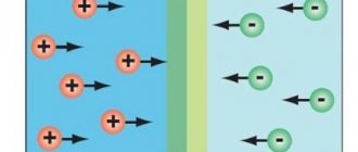
If you don’t delve into the boring theory, then the scheme for overlapping the coils of an axial generator with permanent magnets in practice should look like this.
At each moment of time, identical poles of magnets similarly overlap the windings of the coils of a particular phase.
Alexei2011
This is how it is in real life: everything matches the picture almost 100%, only the coils differ quite a bit in shape.
Let's look at the assembly sequence of an axial generator using the example of a device assembled by user Aleksei2011.
Alexei2011
This time I'm making a disk axial generator. Disc diameter – 220 mm, magnets – 50*30*10 mm. Total – 16 magnets (8 pieces on disks). The coils were wound with wire Ø1.06 mm, 75 turns each. Reels – 12 pieces.
Assessment of the feasibility of installation
Before starting to manufacture a vertical wind generator, they study the weather situation in their region and try to determine whether the unit can provide the required amount of resource.
Experts recommend evaluating the following parameters:
- number of windy days - take the average value for the year when the gust exceeds 3 m/s;
- the amount of electricity consumed per day by a household;
- a suitable place on your own site for wind equipment.
The first indicator is learned from data obtained at the nearest weather station or found on the Internet on the relevant portals. Additionally, they check with printed geographical publications and create a complete picture of the wind situation in their region.
Statistics are taken not for one year, but for 15-20 years, only then the average figures will be as correct as possible and will show whether the generator will be able to fully satisfy the household’s need for electricity or whether its power will only be enough to power individual household needs.
If the owner has a large plot of land located on a slope, near a river bank or in open space, there will be no problems with installation.
When the house is located in the depths of a populated area, and the yard has compact dimensions and is closely adjacent to neighboring buildings, it will not be easy to install a vertical model of a windmill with your own hands. The structure will have to be raised 3-5 m above the ground and further strengthened so that it does not fall in the event of a strong gust.
All this information needs to be taken into account at the planning stage to make it clear whether the wind generator can take over the full energy supply or its role will remain as an auxiliary energy source. It is advisable to first calculate the windmill.
Stator manufacturing
As you can see in the photo, the coils have a shape similar to an elongated drop of water. This is done so that the direction of movement of the magnets is perpendicular to the long side sections of the coil (this is where the maximum EMF is induced).
If round magnets are used, the inner diameter of the coil should approximately match the diameter of the magnet. If square magnets are used, the configuration of the coil turns must be constructed in such a way that the magnets overlap the straight sections of the turns. Installing longer magnets does not make much sense, because the maximum EMF values occur only in those sections of the conductor that are located perpendicular to the direction of movement of the magnetic field.
Stator manufacturing begins with winding the coils. The easiest way to wind coils is using a pre-prepared template. Templates range from small hand tools to miniature homemade machines.
The coils of each individual phase are connected to each other in series: the end of the first coil is connected to the beginning of the fourth, the end of the fourth to the beginning of the seventh, etc.
Let us recall that when connecting the phases according to the “star” circuit, the ends of the windings (phases) of the device are connected into one common unit, which will be the neutral of the generator. In this case, three free wires (the beginning of each phase) are connected to a three-phase diode bridge.
When all the coils are assembled into a single circuit, you can prepare a mold for filling the stator. After this, we immerse the entire electrical part into the mold and fill it with epoxy resin.
Alexei2011
Next I post a photo of the finished stator. Filled with regular epoxy resin. I put fiberglass on the bottom and top. The outer diameter of the stator is 280 mm, the inner hole is 70 mm.
Calculation of a bladed wind generator
Since we have already found out that a horizontal wind generator is much more efficient, we will consider the calculation of its design.
Wind energy can be determined by the formula P=0.6*S*V ³, where S is the area of the circle described by the ends of the propeller blades (sweeping area), expressed in square meters, and V is the estimated wind speed in meters per second. You also need to take into account the efficiency of the windmill itself, which for a three-bladed horizontal circuit will average 40%, as well as the efficiency of the generator set, which at the peak of the current-speed characteristic is 80% for a generator with excitation from permanent magnets and 60% for a generator with an excitation winding. On average, another 20% of the power will be consumed by the step-up gearbox (multiplier). Thus, the final calculation of the radius of a windmill (that is, the length of its blade) for a given power of a permanent magnet generator looks like this: R=√(P/(0.483*V³ ))
Manufacturing a rotor for an axial shaft
Most often, homemade axial generators are made on the basis of a car hub and brake discs compatible with it (you can use homemade metal discs, as Aleksei2011 did). The scheme will be as follows.
In this case, the stator diameter is larger than the rotor diameter. This allows the stator to be attached to the wind generator frame using metal pins.
Alexei2011
There are studs for fastening the M6 stator (3 pieces). This is for generator testing only. Subsequently there will be 6 of them (M8). I think that for a generator of such power this will be quite enough.
In some cases, the stator disk is attached to a fixed axis of the generator. This approach makes it possible to make the design of the generator smaller, but the operating principles of the device do not change.
Opposite magnets must be directed towards each other with opposite poles: if on the first disk the magnet faces the generator stator with its south pole “S”, then the opposite magnet located on the second disk must face the stator with its “N” pole. In this case, magnets located nearby on the same disk must also be oriented in different directions.
The strength of the magnetic field created by neodymium magnets is quite strong. Therefore, the distance between the stator disks and the generator rotor should be adjusted using a pin-threaded connection.
This is a design option in which the rotor diameter is larger than the stator diameter. The stator in this case is attached to the fixed axis of the device.
Also, to adjust the distance between the disks, you can use spacer bushings (or washers), which are installed on the stationary axis of the generator.
The distance between the magnets and the stator should be minimal (1...2 mm). You can glue magnets to generator disks with ordinary superglue. It is best to stick magnets using a pre-prepared template (for example, made from plywood).
This is what preliminary tests of the generator performed by user Aleksei2011 using a screwdriver showed: at 310 rpm, 42 volts were removed from the device (star connection). One phase produces 22 volts. The calculated resistance of one phase is 0.95 Ohm. After connecting the battery, the screwdriver was able to spin the generator up to 170 rpm, and the charging current was 3.1A.
After lengthy experiments, which were associated with the modernization of the working propeller and other smaller-scale improvements, the generator demonstrated its maximum performance.
Alexei2011
Finally, the wind came to us, and I recorded the maximum power of the windmill: the wind intensified, and gusts at times reached 12 - 14 m/s. The maximum recorded power is 476 Watts. With a wind of 10 m/s, the windmill produces approximately 300 watts.
Industrial wind generators: a role model
It's no secret that alternative energy really allows you to get electricity literally from the wind. In European countries, industrial wind generators occupy vast areas and operate autonomously for the benefit of people.
They are enormous in size, located in windswept areas, towering above trees and local objects.
And the wind turbines are installed at a distance from each other. Therefore, accidental breakdowns and damage to one cannot cause harm to neighboring structures.
We will take these principles for creating wind generators as the basis for developing homemade devices. They were created according to scientific developments, tested after long-term operation, and work effectively.
Let's start by analyzing the characteristics of the area where we plan to create a wind power plant.
Wind power plant from a car generator
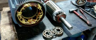
A popular solution among people who practice making wind turbines with their own hands is to remake a car generator for alternative needs. Despite all the attractiveness of such an idea, it should be noted that a car generator in the form in which it is installed on a vehicle engine is quite problematic to use as part of a wind power plant. Let's figure out why:
- Firstly, the winding of the coils of a standard automobile generator consists of only 5...7 turns. Therefore, in order for such a generator to begin charging the battery, its rotor must be spun to approximately 1200 rpm.
- Secondly, magnetic induction in a standard car generator occurs due to the excitation coil, which is built into the rotor of the device. In order for such a generator to operate without connecting to an additional power source, it must be equipped with permanent magnets (preferably neodymium) and certain adjustments must be made to the stator winding.
Mikhail26
A converted autogenerator (with magnets) has the right to life. I have two of these now. In a wind of 8 m/s with two-meter propellers they give an honest 300 watts each.
Converting a car generator to a wind turbine requires some skill. Therefore, it is advisable to start it with experience in rewinding asynchronous motors or generators with a standard cylindrical stator (both of them, if desired, can be converted into an alternative power plant). Remaking a car generator has its own nuances. It will be much easier to understand them if we turn to the experience of users who have achieved certain success in this area.
Legality of installing a wind generator
Alternative energy sources are the dream of any summer resident or homeowner whose plot is located far from central networks. However, when we receive bills for electricity consumed in a city apartment and look at the increased tariffs, we realize that a wind generator created for domestic needs would not hurt us.
After reading this article, perhaps you will make your dream come true.
A wind generator is an excellent solution for providing a country property with electricity. Moreover, in some cases, installing it is the only possible solution.
In order not to waste money, effort and time, let's decide: are there any external circumstances that will create obstacles for us during the operation of the wind generator?
To provide electricity to a summer house or small cottage, a small wind power plant with a power not exceeding 1 kW is sufficient. Such devices in Russia are equated to household products. Their installation does not require certificates, permits or any additional approvals.
In order to determine the feasibility of installing a wind generator, it is necessary to find out the wind energy potential of a particular area (click to enlarge)
There is no taxation on the production of electricity, which is spent on meeting one’s own household needs. Therefore, a low-power windmill can be safely installed, using it to generate free electricity, without paying any taxes to the state.
However, just in case, you should ask if there are any local regulations regarding individual power supply that could create obstacles in the installation and operation of this device.
Your neighbors may have claims if they experience inconvenience caused by the operation of the windmill. Don't forget that our rights end where other people's rights begin.
Therefore, when purchasing or independently manufacturing a wind generator for your home, you need to pay serious attention to the following parameters:
- Mast height. When assembling a wind generator, you need to take into account the restrictions on the height of individual buildings that exist in a number of countries around the world, as well as the location of your own site. Please be aware that structures taller than 15 meters are prohibited near bridges, airports and tunnels.
- Noise from gearbox and blades. The parameters of the generated noise can be determined using a special device, and then the measurement results can be documented. It is important that they do not exceed established noise standards.
- On-air interference. Ideally, when creating a windmill, protection against TV interference should be provided where your device can cause such troubles.
- Environmental Services Claims. This organization can prevent you from operating the installation only if it interferes with the migration of migratory birds. But this is unlikely.
When creating and installing a device yourself, learn these points, and when purchasing a finished product, pay attention to the parameters that are in its passport. It’s better to protect yourself in advance than to be upset later.
- The feasibility of installing a wind turbine is justified primarily by the sufficiently high and stable wind pressure in the area;
- It is necessary to have a sufficiently large area, the usable area of which will not be significantly reduced due to the installation of the system;
- Due to the noise that accompanies the operation of a windmill, it is advisable that there be at least 200 m between the neighbors’ homes and the installation;
- A convincing argument in favor of installing a wind generator is the steadily increasing cost of electricity;
- The installation of a wind generator is possible only in areas where the authorities do not hinder, but rather encourage, the use of green energy;
- If there are frequent interruptions in the region where a mini power plant is being built that processes wind energy, the installation will minimize the inconvenience;
- The owner of the system must be prepared for the fact that the funds invested in the finished product will not pay off immediately. The economic effect can become noticeable in 10 - 15 years;
- If the payback of the system is not the last moment, you should think about building a mini power plant with your own hands.
Cable twist protection
As you know, the wind does not have a constant direction. And if your wind generator rotates around its axis like a weather vane, then without additional protective measures the cable running from the wind generator to other elements of the system will quickly twist and become unusable within a few days. We bring to your attention several ways to protect yourself from such troubles.
Method one: detachable connection
The simplest, but completely impractical method of protection is to install a detachable cable connection. The connector allows you to untangle a twisted cable manually, disconnecting the wind generator from the system.
w00w00 FORUMHOUSE user
I know that some people put something like a plug with a socket at the bottom. The cable got twisted and I unplugged it from the outlet. Then he unscrewed it and stuck the plug back in. And the mast does not need to be lowered, and current collectors are not needed. I read this on a forum on homemade windmills. Judging by the author's words, everything works and the cable does not twist too often.
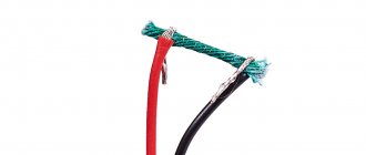
Method two: using a rigid cable
Some users advise connecting thick, elastic and rigid cables (for example, welding cables) to the generator. The method, at first glance, is unreliable, but has the right to life.
user343 FORUMHOUSE user
I found it on one site: our method of protection is to use a welding cable with a hard rubber coating. The problem of twisted wires in the design of small wind turbines is greatly overestimated, and welding cable #4...#6 has special qualities: hard rubber prevents the cable from twisting and prevents the windmill from turning in the same direction.
Method three: installing slip rings
In our opinion, only installing special slip rings will help to completely protect the cable from twisting. This is exactly the method of protection that user Mikhail 26 implemented in the design of his wind generator.
Advantages and principle of operation of wind turbines
A modern vertical generator is one of the alternative energy options for the home. The unit is capable of converting gusts of wind into an energy resource. For correct operation, it does not require additional devices that determine the direction of the wind.
A rotary wind generator is very easy to make with your own hands. Of course, he won’t be able to completely take on the responsibility of providing energy to a large private cottage, but he will do an excellent job of lighting outbuildings, garden paths and local areas.
The vertical type device operates at a low height. Its maintenance does not require various devices to ensure safe high-altitude repair and maintenance work.
A minimum of moving parts makes the wind turbine more reliable and operationally stable. The optimal profile of the blades and the original shape of the rotor provide the unit with a high level of efficiency, regardless of which direction the wind is blowing at any given moment.
Small household models consist of three or more light blades, instantly catch the weakest gust and begin to rotate as soon as the wind force exceeds 1.5 m/s. Thanks to this ability, their efficiency often exceeds that of larger installations requiring higher winds.
The generator operates absolutely silently, does not disturb owners and neighbors, does not create harmful emissions into the atmosphere and reliably serves for many years, carefully supplying energy to living quarters.
A vertical wind generator operates on the principle of magnetic levitation. As turbines rotate, impulse and lift forces are generated, as well as actual braking forces. The first two cause the blades of the unit to rotate. This action activates the rotor and it creates a magnetic field that produces electricity.
A wind turbine with a vertical axis of rotation is not inferior in efficiency to its horizontal counterparts. In addition, it makes no claims to the territorial location and works fully in almost any place convenient for homeowners
The device functions completely independently and does not require the owner’s intervention in the process.
Wind turbine protection from storms
We are talking about protecting the device from hurricanes and strong gusts of wind. In practice, this is implemented in two ways:
- Limiting the speed of the wind wheel using an electromagnetic brake.
- By moving the plane of rotation of the propeller away from the direct influence of the wind flow.
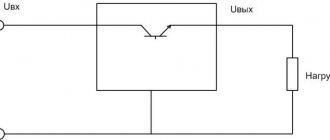
The first method is based on connecting a ballast electrical load to a wind generator. We have already talked about it in one of the previous articles.
The second method involves installing a folding tail, which allows you to direct the propeller towards the wind flow at nominal wind strength, and during a storm, on the contrary, to move the propeller out of the wind.
Protection by folding the tail occurs according to the following scheme.
- In calm weather, the tail is positioned slightly at an angle (down and to the side).
- At rated wind speed, the tail straightens and the propeller becomes parallel to the air flow.
- When the wind speed exceeds the nominal value (for example, 10 m/s), the wind pressure on the propeller becomes greater than the force created by the weight of the tail. At this moment the tail begins to fold and the propeller moves out of the wind.
- When the wind speed reaches critical values, the plane of rotation of the propeller becomes perpendicular to the wind flow.
When the wind weakens, the tail, under its own weight, returns to its original position and turns the propeller towards the wind. In order for the tail to return to its original position without additional springs, a rotating mechanism with an inclined pin (hinge) is used, which is installed on the tail rotation axis.
The tail rotation axis is set at an angle: 20° relative to the vertical axis and 45° relative to the horizontal axis.
In order for the mechanism to perform its main function, the axis of the mast must be at a certain distance from the axis of rotation of the turbine (optimally 10 cm).
To prevent the tail from folding and falling under the propeller during sharp gusts of wind, limiters must be welded on both sides of the mechanism.
An Excel table with ready-made formulas will help you calculate the tail dimensions and their dependence on other parameters of the wind turbine. In it, the area of variable values is indicated in yellow.
The optimal tail area is 15%...20% of the wind wheel area.
We present to your attention the most common option for mechanical protection of a wind generator. In one form or another, it is successfully used in practice by users of our portal.
WatchCat User FORUMHOUSE
During a storm, you need to slow down the propeller by moving it out of the wind. For example, when the wind is too strong, my windmill tips over with its propeller facing up. Not the best option, because returning to the working position is accompanied by a noticeable blow. But in ten years the windmill did not break down.
Do-it-yourself windmills for home: review of designs
As you already understood, the very first part that receives wind energy is the wind wheel. Not a single windmill scheme for a home can do without it.
It can be done:
- with a vertical axis of rotation;
- or horizontal.
Vertical wind generator
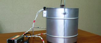
I’ll show you a photograph of one of the easy-to-manufacture structures, made from an ordinary steel barrel.
Such a vertical wind generator, made by hand, and located above the ground itself, surrounded by buildings and plants, will not be able to develop normal speed to generate enough electricity to power a private house.
It will be able to perform only some single tasks for low-power equipment. Moreover, the low rotation speed of its rotor will require the mandatory use of a step-up gearbox, which means additional energy losses.
Such designs were popular at the beginning of the last century on steamships. The water wheel, with its blades located along the direction of movement of the vessel, ensured its movement.
Now it is a rarity that has lost its relevance. In aviation, such a design not only did not take root, but was not even considered.
Onipko rotor
Among low-speed wind wheel designs, the Onipko rotor is now being widely distributed via the Internet. Advertisers show it spinning even in very light winds.
However, for some reason I also have a critical attitude towards this development, although repeating it with your own hands is not so difficult. I did not find rave reviews among buyers, nor did I find scientific calculations of the economic feasibility of its use.
If any of the readers can dissuade me from this opinion, I will be grateful.
Horizontal wind generator
From the very beginning, aircraft engines began to use a propeller that drives air flow along the body of the aircraft. Its shape and design are chosen so as to use a reactive component in addition to the active pressure force.
Any horizontal wind generator, whether made industrially or with your own hands, works on this principle. I show an example of a homemade design with a photograph.
Based on the principle of using wind energy, this is a more efficient design, and in terms of its design, it is low-power for providing household energy supply issues.
A small electric motor, the rotor of which spins a windmill, can, even with optimal pressure and wind strength, produce only low power as a generator. You can connect a weak LED light bulb to it.
Think for yourself whether you need to assemble such a weather vane with lighting or not. This design will not cope with other tasks. Although it can still be used to scare away moles on the site. They really don't like noises accompanied by the rotation of metal parts.
In order to fully use the electricity obtained from the wind, the impeller of the wind generator must have dimensions corresponding to the power consumption. Count on approximately five meters in diameter.
When creating it, you will encounter a technical difficulty: you will have to accurately balance large parts. The center of mass must always be at the midpoint of the axis of rotation.
This will minimize bearing beating and rocking of the structure located at a high altitude. However, this balancing act is not so easy to achieve.
How to install a wind generator: a reliable mast diagram for mounting at height
The weight of the impeller for normal production of electrical energy is quite decent. It cannot be installed on a simple stand.
It will be necessary to create a solid concrete foundation for the metal mast and guy anchor bolts. Otherwise, the entire structure, assembled with great difficulty, may collapse at any inopportune moment.
A stand for a wind generator raised to a height can be made:
- in the form of a prefabricated mast assembled from sections with braces;
- or conical tubular support.
Both schemes will require reinforcement against capsizing by creating several tiers of guy ropes, which are necessary to hold the mast in heavy gusts of wind. They will have to be securely attached to stoppers and anchors.
From personal unsuccessful experience: while using analog television, the “Spider Web” antenna with a hoop diameter of 2 m worked. It was located at a height of 8 meters and was fixed on a wooden pole with two levels of guy wires. Heavy gusts of wind rocked it so much that the stand fell apart.
Modern digital television, fortunately, requires the use of much smaller antennas. Not only are they easy to make with your own hands, but they are also not that difficult to attach.
How to make a mast for a windmill
Immediately pay attention to creating a durable, trouble-free structure. Otherwise, just repeat the sad experience of YantarEnergo workers, who had an accident during a storm: a multi-ton mast collapsed, and fragments from the blades scattered throughout the area.
The construction of the mast will require calculating the amount of materials required to create a structure from a steel angle of various sections. The shape and dimensions are selected according to local conditions.
It is made of three or four vertical posts. Each of them is mounted on a stop from below. At the top of the mast a platform is created for installing a wind turbine.
Since the length of the corners is limited, the mast is assembled from several sections. The rigidity of the overall fastening is provided by side ribs attached through braces.
A mandatory element of the foundation are embedded metal elements. They will be used to fasten parts. You will have to take care of welding and connecting bolts.
Don't neglect additional braces.
How to make a pipe support
A telescopic structure made from steel pipes of the appropriate profile is easier to assemble, but it should be more carefully calculated for strength. The bending moment created by the heavy top during a storm wind should not exceed a critical value.
In this case, difficulties will arise with preventive maintenance, inspection and repair of the assembled air power plant. If you can climb to a height using a mast like a ladder, it is problematic to do this using a pipe. And working at the top is very dangerous.
Therefore, it is immediately necessary to consider the option of safely lowering the equipment to the ground and an accessible way to lift it. This allows you to do one of two schemes with:
- Rotary axis on the main support.
- The thrust lever on the bottom of the support post.
In the first case, a solid foundation is created for installing the main support. A welded pipe structure with a windmill and a pulley system on steel cables is attached to its axis of rotation.
There is a counterweight located at the bottom of the pipe, which facilitates the work of lifting and lowering using a hand winch.
The picture does not show the safety ropes of the guy belts. They simply hang from their mountings down to the ground as the mast is raised and lowered, and are attached to permanent concrete stakes for permanent operation.
The diagram for installing and lowering the windmill according to the second option is shown below.
The mast and a thrust lever with a counterweight located at right angles to it, reinforced with a stiffening rib, are turned in the vertical direction by a winch with a pulley system.
The axis of rotation of the created structure is located at the apex of the right angle and is fixed in guides built into the foundation. When raising or lowering the mast, the guy ropes are removed from the stationary fastenings on the ground. They can be used as safety lines.
Wind generator: device and principle of operation of the electrical circuit in simple words
Industrial wind farms are designed to be able to immediately supply electrical energy to the grid for consumers. You can't do this with your own hands.
When choosing a generator that will spin a wind wheel, the principle of reversibility of electric machines is used. Torque is applied to the electric motor and the stator windings are excited.
However, the idea of spinning the rotor of a three-phase asynchronous electric motor as a generator to produce an electric current of 220/380 volts is realized from internal combustion engines, water pressure, but not wind.
The overall design of the generator with the rotor will have a lot of weight, otherwise it will not be possible to ensure high shaft speeds.
For small capacities you can:
- use a car generator that produces 12/24 volts;
- use a wheel motor from an electric bike;
- assemble a structure from neodymium magnets with coils of copper wire.
You can also use a windmill sold in China as a basis. But he needs to immediately carry out an audit: pay attention to the quality of installation of the windings, the condition of the bearings, the strength of the blades, and the overall balancing of the rotor.
You will have to be prepared for the fact that the output voltage of the generator will vary greatly depending on the wind speed. Therefore, batteries are used as an intermediate link.
They must be charged by the controller.
Household appliances on a 220-volt network must be powered by alternating current from a special converter - an inverter. The simplest diagram of a home wind power plant is as follows.
It can be significantly simplified because consumer digital electronics: computers, televisions, telephones operate on DC 12 volt power supplies.
If they are excluded from operation and digital equipment is powered directly from batteries, then electrical energy losses will be reduced by eliminating double conversion in the inverter and units.
Therefore, I recommend making separate 12-volt sockets and powering them directly from batteries.
Inside the electrical circuit, you will have to maintain the same power balance as in the mechanical design. Each connected load must comply with the energy characteristics of the upstream source.
220 volt household appliances should not overload the inverter. Otherwise, it will be disconnected from the built-in protection, and if it malfunctions, it will simply burn out. Batteries, power contacts of the controller, and the generator itself work on the same principle.
Circuit breaker protection of a domestic wind turbine must be carried out without fail.
To do this, it must be correctly selected strictly according to scientific recommendations, tested and adjusted.
An accidental overload, much less the occurrence of a short circuit current, cannot be foreseen. Therefore, this module must be installed as the main protection.
The connection diagram for batteries, inverter and controller for a wind generator is practically no different from that used in solar stations with light panels.
Therefore, a reasonable conclusion immediately suggests itself: to assemble a combined home power plant powered by wind and solar energy simultaneously. These two sources together complement each other well, and the cost of assembling single stations is significantly reduced.
There are a lot of channels on YouTube dedicated to wind generators for the home. I liked the work of the owner of Solar Panels. I believe that he is quite objective when presenting this topic. Therefore, I recommend that you take a closer look.
Batteries for a wind generator: another problem for the home owner
One of the costly challenges of a wind or solar power plant is the issue of storing electrical energy, which only batteries can solve. They will have to be purchased and updated, and the cost is quite high.
To select them, you need to know the operating characteristics: voltage and capacitance. Usually, composite batteries from 12 V batteries are used, and the number of ampere-hours in each specific case should be determined experimentally, based on the power of consumers and their operating time.
You will have to choose batteries for a wind generator from a fairly wide range. I will limit myself to not a complete review, but only to four popular types of acid batteries:
- conventional automotive starter;
- AGM type;
- gel;
- armored.
Sellers do not recommend purchasing starter batteries for wind power plants because they are designed to operate in critical vehicle operating conditions:
- when stored in cold weather, they must withstand the enormous starter currents that are created when spinning up a cold engine;
- are subject to vibrations and shaking while driving;
- recharging occurs in buffer mode from the generator when the car is moving at different engine speeds.
Wherein:
- serviced batteries, requiring periodic electrolyte levels and topping up with distilled water, are designed to withstand 100 discharge/charge cycles;
- maintenance-free - have a more complex design and the number of cycles is 200.
However, the wind generator battery when used inside the house:
- usually placed in the basement, where the temperature, maintained year-round at +5÷+10 degrees, is optimal;
- not subject to shocks and vibrations, permanently installed in a stationary state;
- do not receive extreme loads during starter start, and when turning on household appliances through the inverter, they operate in a gentle mode;
- are charged from the generator with small currents, which have a beneficial effect on the desulfation mode of the plates.
All this is the most favorable conditions for their operation. Therefore, I suggest taking note of this option for those who are not too lazy to periodically monitor the voltage on the banks and monitor the electrolyte level in them.
AGM batteries are more complex in design. They have the same plates, but glass mats are impregnated with acid, which simultaneously act as a dielectric layer. Their discharge/charge cycle is 250÷400. Overcharging is dangerous.
Goal batteries are also created with a maintenance-free design with a sealed case and an electrolyte thickened to a gel state. They really don't like overcharging, but are more resistant to deep discharge. The number of calculation cycles is 350.
Armor-mounted batteries are among the most modern developments. Their electrode plates are protected by polymers from acid attack. Range of operating cycles: 900÷1500.
All these four types of batteries differ significantly in price and operating conditions. If you take into account the recommendations of sellers, you will have to shell out a fairly decent amount of money.
However, I recommend that you first listen to the useful advice that the same owner of “Solar Batteries” gives in his video “How to choose batteries for a wind farm and a solar station.”
He has his own, opposite opinion on this matter. How you treat him is your own business. However, to know information from opposing sources and choose the most suitable option from it: the optimal solution for a thinking person.
The undeniable benefits of a wind generator
After viewing numerous photos of a homemade wind generator, individuals interested in the work are faced with the question of how practical a stationary installation will be.
The design can act as an additional and permanent source of electricity.
Thanks to the functioning of the device, it will be possible to operate such devices as:
- Lamps.
- Heating equipment.
- Household appliances.
- Boilers.
Schemes that require the presence of a battery have proven themselves to be excellent; it accumulates a resource if there is no need to supply the building at the moment.
Important! To implement high-quality heating of the entire building area, it is enough to create a structure with a power rating of 4 kW.
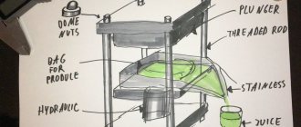
Hand spit design
The device is extremely simple: two stands, a spit rod and a handle. This is the minimum set. Add fork clamps to keep the meat from turning and you will get an ascetic, but very workable design.
You can also equip the spit on the handle side with a disk with holes. With its help, you can fix the meat with a certain side over the fire.
The stands could also be improved. If a ring-hole is sufficient on the side of the tip of the skewer, then on the side of the handle it is better to make an inclined groove. This will allow you to put the spit on the fire without disconnecting the handle.
Design requirements
Of course, a spit for cooking barbecue must meet a number of characteristics. The taste and doneness of meat depends on the correctly selected device.
- For a regular kebab of 100-200 grams, a spit whose thickness does not exceed 0.7 centimeters is suitable.
- A whole chicken carcass or a young colic can be supported by a device up to 1.7 centimeters thick;
- If it is necessary to prepare the carcass of a larger animal, a pig or a sheep, then a structure with a thickness of at least 1.5 centimeters will be required.
It is also important to choose the correct section. It will be problematic to fry meat on a round spit. The same thing will happen with a flat section, because it is too thin.
Reference! The best option is a triangular section.
A little physics for those who decide to seriously tackle the problem of water supply
The operation of a submersible pump is based on the rotational movements of a crank mechanism. A conventional wind generator allows the device to be put into operation. Its effectiveness has been proven by the practical experience of many summer residents who were able to understand the nuances of the mechanism and design it themselves. Indeed, despite its apparent complexity, you can assemble a wind pump with your own hands quite quickly and at minimal cost. The only condition is that when performing calculations and developing drawings, it is important to take into account several points:
- The deeper the well, the more energy is required to operate the pump, and the more powerful the new wind generator must be.
- For stable operation of the submersible mechanism of a wind water pump, there must always be some force on its rod. Otherwise, water will be supplied intermittently.
- When designing a wind turbine, it is necessary to take into account the strength of the wind on the site. The larger the device model, the more wind energy is required to run it. In light winds, such a generator will be at rest. But a large windmill has high power, unlike more compact models.
Experience shows that the initial choice in favor of a large wind generator eventually makes you think about purchasing or manufacturing a medium-sized device. Some power losses in this case are compensated by the stable operation of the windmill even at low air flow speeds. Moreover, in most parts of the country strong winds are observed relatively rarely.
Dispute about section
Choosing the cross-section of the rod for the spit is the first thing that comes to mind. There is no universal solution and much depends on the type of spit.
What are they:
- Trident skewer.
- Rotisserie with forks or clamps. Suitable for roasting carcasses.
- Rotate the rod. For the lightest and least crumbly pieces. Good in hiking conditions.
We discard the flat section immediately: when rotating, the piece of meat will periodically sag significantly. This is inconvenient for a manual spit and an extra load on the mechanism for an electric one. The idea that on a square rod, compared to a round one, the meat does not turn, discard forever. It turns and even starts to wobble.
For a simple rod skewer, both round and square rods will work.
For the trident skewer, this issue is also not fundamental.
In the version with clamps or forks, it is better to choose a square section of the rod. This makes it easier to secure the clamps against rotation and will allow you to confidently rotate large asymmetrical pieces.
1 - fork; 2 - handle; 3 — handle fastening; 4 — disk for fixing the trochanter; 5 - skewer spindle.
Manual and electric drive
Let's look at the differences, pros and cons.
Hand spit.
Pros:
- Easy to use, difficult to break anything;
- Easy to do.
Minuses:
- Requires constant attention from the cook and skills in working with a spit are required;
- Physically expensive (after all, frying time is several hours).
Electrically driven.
Pros:
- Removes the need for the cook to be at the spit and there is no fatigue from its rotation;
- The rotation is uniform and the meat cooks better;
- You can select the desired rotation speed and easily maintain it.
Minuses:
- This is a complex mechanism and not everyone can make it on their own;
- Drive elements are expensive;
- The design is more “gentle” than a manual drive;
- Requires a source of energy.
Types of mechanical spits
In addition to the classic design with manual rotation, there is a design that includes an electric drive.
Reference! If you choose an automatic spit with an electric drive, then you don’t have to bother with the degree of frying. The meat will cook on its own, and the cook can do his own thing.
Hand spit
This is an option where the cook will have to independently activate the rotation mechanism. The length of the rods should be selected according to the size of the grill. The optimal material for the job is stainless steel. Special antennae and a handle are mounted to this rod. The handle must be made of a non-heating material, otherwise there is a risk of getting burned.
The structure is mounted above the grilling surface of the grill. Plates for fastening the racks are mounted on one side. On the opposite side there should be a rod with an oval connector. a necessary element for easy rotation.
Electric spit
This option can ensure uniform rotation of the meat. The gearbox for such a spit can be made independently.
- A bicycle sprocket is attached to the shaft area;
- A gear is welded to it;
- A shaft with a bearing is mounted on the engine housing;
- A gear is attached near the handle, identical to the diameter of the one attached to the sprocket;
- The assembled engine is installed on one of the supports;
- Using a bicycle chain, the sprockets are connected, this is what will ensure correct interaction with the electric drive.
Reference! Carefully monitor the sizes of the stars, they must be identical.
Safety Tips
When installing an electric spit with your own hands, you should strictly monitor safety precautions and follow certain rules.
- The most important rule is to monitor the voltage of the electrical network. If the voltage starts to jump, you must immediately disconnect it from the power supply.
- Carefully monitor the integrity of the winding.
- When parts wear out and become deformed, do not forget to replace them in a timely manner;
- Do not forget about the basic rules for storing electrical equipment and the main elements of the spit.
If you follow all safety rules and the proposed instructions, you can independently build an automatic grill with an electric drive. Failure to follow basic safety rules can greatly harm your own health.
An electric grill spit will solve many problems related to cooking meat outdoors. The main thing is not to forget about safety precautions and the basic properties of such a design. This design can be purchased at a special store, or made independently. The collapsible design is easy to transport with you, regardless of the place and time of rest.