© 2015 Vasili-photo.com
I bring to your attention a translation of the article “An Interesting Distance Meter” by Edward J. Ramaley, published in the magazine “American Photography” for February 1939. The article describes how an original optical rangefinder can be made from a piece of cardboard. Of course, these days most cameras are equipped not only with a rangefinder, but with full-fledged autofocus, which greatly reduces the practical significance of the primitive device described in the article. Nevertheless, the homemade device remains a very entertaining toy, with wide entertainment and educational potential and allows you to take a slightly new look at the work of your own eyes.
The style of presentation may seem somewhat confusing in places, but this is how it is in the original - I tried to translate as close to the text as possible.
The purpose of a rangefinder in photography is to enable the photographer to focus the lens on a subject without having to measure the distance separating them with a ruler or tape measure. Focusing is accomplished by changing the distance between the lens and the image in accordance with the distance from the lens to the subject. Careful focusing is especially necessary when the lens aperture diameter is large enough compared to its focal length. In general, any lens used at its maximum aperture needs to be focused extremely carefully when shooting close subjects.
An optical rangefinder collects light through two receiving systems, which are coupled in such a way that the two images they generate can be combined into one. Proper adjustment of this device can be tied to the position of the pointer on the scale, or directly to the focusing of the photographic lens. Based on this, it might seem logical to use our own pair of eyes directly as an optical rangefinder, which can be implemented in several ways. One is to use an individually calibrated scale held at arm's length and observed to measure the convergence of the eyes looking at an object.
Rangefinder calibration
Cut a triangle from cardboard with a base of three inches and a height of eight inches. From a window or other light source, set the shortest distance indicated on the focusing scale of your camera, and the measurer stands at this point facing the light. The triangle should be held opposite the window in front of the eyes at arm's length, using natural muscle effort, which could be reproduced at will. By focusing your eyes on the window, you will see that the triangle appears double, since each eye is looking at it from its own point of view. While still maintaining focus on the window, you can apply a straight ruler across the triangle, parallel to its base, so that it intersects the edges of each of the two imaginary triangles at the point of their mutual intersection. Finally, a line is drawn along the ruler. This completes the calibration for this distance.
The full focusing scale of your camera is applied to the cardboard triangle in exactly the same way: stepping back from the window at the appropriate distance, determine where the two imaginary triangles intersect and draw a horizontal line through this intersection. The rangefinder's accuracy decreases as the distance increases, but so does the need for critical focus. The accompanying drawings show what the completed rangefinder looks like and how it appears when the eye is focused on a point behind it.
| Rice. 1 Rangefinder (for the author’s eyes and hands). | Rice. 2 View of the rangefinder when the eyes are focused on the object behind it. |
The simplest barometric altimeter based on Arduino.
Device functions: — Measuring the current height and displaying it on the LED display.
— Memorizing the maximum altitude value that has occurred since the power was turned on. — Display of the maximum height by pressing a button. — Recording the maximum height value into the non-volatile memory (EEPROM) of the controller (saved after power is turned off). - Reading the stored maximum height from the EEPROM and displaying it on the display. The zero reference point is the altitude at which the device’s power was turned on.
What you will need (in parentheses are keywords for searching on all sorts of ebays, etc.) - an Arduino microcontroller, in principle, almost any will do if the code is adapted, but everything was assembled and tested on the basis (Arduino Nano).
— barometric altitude sensor with I2C bus (BMP085). — three-digit seven-segment LED display with a common anode (7-Segment LED Display). — wires to connect it all into a single whole, I used ready-made ones with connectors, but this is not at all necessary (Dupont Wire). — a button, any without fixing the position will do (Tact Switch Push Button). For example, this: - a resistor from 1KOhm to 10KOhm. - three 100 Ohm resistors. - a soldering iron with all the gobules and the ability to use it. — Arduino Software.
Optional: - development board for display wiring.
For those who are completely off topic. Before trying to assemble the device and delve into the code, I strongly recommend visiting and reading several resources: Introduction to the topic, simple examples. About connecting a seven-segment display with examples. Description of the sensor, examples, libraries. It won’t take much time, it will greatly increase your understanding =)
Connection diagram of device elements (clickable):
Anticipating questions from the series “what, couldn’t draw a normal diagram?!” I’ll say that I could, but for the uninitiated I think this option will be easier to understand, but for the initiated it doesn’t matter, and so the diagram is read normally. I found the seven-segment pinout only for the four-bit version; the three-bit version differs simply by the absence of the 6th leg.
As for the power supply of the device: the Arduino in its original form can normally survive from 7V to 16V, in extreme cases from 6V to 20V. But, considering that I had a Chinese clone, I didn’t try any vile experiments, but the LiPo 3S battery works without problems. It is advisable to pack the sensor in such a way that air access is free, but at the same time exclude direct air flow into the hole in the sensor, for example, cover it with foam rubber. I recommend removing the RX and TX LEDs from the Arduino board, because... they are connected in parallel to digital pins 0 and 1, which is why the segments connected to these pins will glow with less brightness.
I plan to use the device on a training FPV pepelats, on which to install the OSD toad strangles, and this thing can be placed in the field of view of the camera. In theory, you can build a battery voltage sensor into the same unit and switch the display output of one or another parameter using the RU channel for this, but for this I have a separate voltmeter and did not bother.
A few photos: I did not solder all the pins, but only those that will be used. At the same time, I used curved ones and placed them on both sides of the board.
I soldered the display on a breadboard, I don’t like to etch boards, and I’m too lazy =)
When connecting the display, do not forget about current-limiting resistors!
I gathered all the noodles into a pile.
Packed.
General form.
As for the design: it was made for a specific application and in my case these bunches of noodles are justified, it will be more convenient to place on the pepelats. If you make it as a single device and there is no need to place the display in the camera field, then it is quite possible to pack it in some kind of case with a minimum number of protruding wires, the main thing is not to close the case hermetically.
Assembled weight is about 20g.
I checked the device while riding the elevator to the 12th floor, it shows quite adequately.
That's all. Thank you for your attention! Let me remind you once again that competent criticism, reviews and suggestions are welcome!
Source
How to use a rangefinder
In practical use, the scale is held vertically at arm's length while the eyes are focused on a significant part of the scene. The thumbnail slides up the scale until the two triangles appear to intersect, at which point the eye can move to the triangle to see which line the nail marks and focus the camera accordingly. It would seem that nothing could be simpler, but there are some annoying obstacles that should not be forgotten.
Our eyes deceive us. Sometimes we think we are looking exactly at an object, but in reality our eyes are focused on a point in the air. The remedy for this is to take several readings quickly enough, without giving your eyes time to tire or hesitate. Repeat until consistent results are obtained. It should also be remembered that the pupil of the eye is not a point, and its size in bright light is not the same as in dim light. As a result, there is a certain lack of precision at the far end of the scale, and when reading the scale you have to use approximately the same brightness as when calibrating. This effect is reduced if you perform the calibration in moderately bright light and look at the light of the same intensity immediately before reading.
The mathematical relationship and rationale for this device is shown in Fig. 3, and, as can be seen, the distance between the eyes is quite significant for large distances. The idea is that if the scale is calibrated in a bright room and is also used in a bright room, the distance between the eyes does not change. Meanwhile, in dark places the eye pupil dilates, thus exaggerating some values and downplaying others.
Another source of instability, namely, the difficulty of keeping the scale always at the same distance, is very easily overcome by very little practice, by the use of a natural position and comfortable muscular effort. Errors in holding the triangle are especially significant at close ranges.
This device is not suitable for commercial production, since it must fit a specific pair of eyes and a specific hand. It costs nothing and can be made in half an hour, but when used with due care, it turns a pair of keen eyes into an excellent rangefinder that requires no excuse. Continued use of this device in photographing children at play at close range and with the aperture wide open produced many satisfactory negatives and demonstrated the usefulness of the device.
Fig. 3 Curves showing the dependence of the length of marks on the scale on the distance to the object for an arm length of 27 inches and various distances between the eyes. CD is the length of the line on the scale in inches. BE is the distance from the eyes to the object in feet. AB is the distance between the eyes in inches.
***
Homemade scanning laser rangefinder
In this article I will talk about how I made a homemade laser scanning rangefinder using the triangulation principle of distance measurement, and about the experience of using it on a robot.
Why do you need a scanning rangefinder?
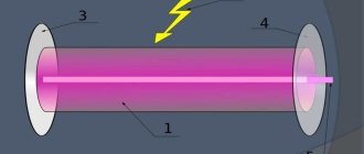
To date, there are not many methods for indoor navigation in robotics. Determining the robot's position in space using a laser scanner is one of them. An important advantage of this method is that it does not require the installation of any beacons indoors. Unlike systems that use image recognition from cameras, processing data from a rangefinder is not so resource-intensive. But there is also a drawback - the complexity, and accordingly, the price of the rangefinder. Traditionally, robotics uses laser scanners that use the phase or time-of-flight principle to measure the distance to objects. The implementation of these principles requires rather complex circuitry and expensive parts, although the characteristics are decent - using these principles, you can achieve high scanning speed and a long distance measurement range. But such scanners are not suitable for home experiments in robotics - their prices start at $1,000. Rangefinders that use the triangulation principle of distance measurement come to the rescue. This type of rangefinder first appeared in Neato robotic vacuum cleaners:
Quite quickly, amateurs deciphered the protocol of this rangefinder and began to use it in their projects. The rangefinders themselves appeared on ebay as spare parts in small quantities at a price of about $100. A few years later, the Chinese company was able to release the RPLIDAR scanning rangefinder, which was supplied as a full-fledged device, and not a spare part. Only the price of these rangefinders turned out to be quite high - $400.
Homemade rangefinder
As soon as I learned about Neato rangefinders, I wanted to build one myself. In the end, I succeeded, and I described the assembly process on the Roboforum. First version of the rangefinder:
Later, I made another version of the rangefinder, more suitable for use on a real robot, but I was not completely satisfied with its quality of work. The time has come for the third version of the rangefinder, and it is this that will be described below.
Translator's afterword
One cannot help but pay tribute to the author’s ingenuity, although the literary side of the article, of course, leaves much to be desired.
It is not entirely clear to me how changing pupil size can affect the distance between the pupils. Obviously, the author does not mean the distance between the centers of the pupils, but rather the distance between their medial edges. In my opinion this is not entirely correct. In the end, the optical axis of the eye passes through the center of the pupil, and therefore for our purposes it is the distance between the centers of the pupils that is important, which does not depend on their diameter. True, when the pupil dilates (mydriasis), the depth of sharply imaged space decreases, as a result of which out-of-focus objects (including the double triangle of the rangefinder) will look somewhat blurrier. This slightly reduces the accuracy of the measurement, but not so much that this fact is worth paying special attention to.
| Fig.4 This is what a metric rangefinder looks like. |
The precision of rangefinder calibration empirically, i.e. literally by eye, also raises certain doubts in me. The measurement method is too inaccurate (especially for long distances) to be used when marking a reference scale. In my opinion, it is better to calculate the location of the horizontal marks on the rangefinder scale. I even came up with an algorithm that can make this task easier. All you need is to ask someone to measure the distance between the centers of your pupils (with your eyes looking into the distance), as well as the distance from the eyes to the rangefinder scale held at arm's length, then insert the resulting numbers into the appropriate cells of the form and press Click the “Build table” button. For each distance, you will receive the height of the corresponding horizontal mark, counting from the base of the triangle, as well as its length (segment CD in Figure 3). All measurements are, of course, metric.
DIY rangefinder for hunting
Good day, readers! I'm sure I'm not the only one wondering about purchasing, or better yet creating, a fairly accurate rangefinder with my own hands, with the ability to measure distances of at least several kilometers. A long time ago I became acquainted with interesting material, thanks to which I learned to approximately measure distances using the “thousandths” method. When using this method, as you know, you need to know the dimensions of the remote object. Those who have encountered this know that in the mountains it is difficult to find an object with familiar dimensions. Therefore, I also wanted to have another method that did not require prerequisites. Yesterday, I accidentally came across the design of a homemade optical rangefinder on the Internet. Next is a little copy-paste: “It is difficult to determine the distance by eye. More or less a person copes with this task on level ground. If there is a ravine or river between the object and the observer, then you can make a mistake two to three times.
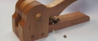
A mirror rangefinder will help you accurately estimate the distance to various objects.
Make blanks from 33 mm plywood, thin planks or other rigid sheet material, connect them with wood glue into a longitudinal case, leaving the top cover 4 open. End walls 5 are made after the gutter from parts 1, 2 and 3 has already been glued together. Then At the top of the box, attach mirror strips measuring 25x50 mm, as shown in the figure. Glue mirror A tightly with BF-2 glue to the block connecting parts 2 and 5, and mirror B to the flat of the rotating axis. Insert this axis with the lower end into the hole of part 3, cover the case with lid 4 so that the upper end of the axis falls into the hole of part 4. Place an arrow-pointer (made of tin or aluminum) on the upper end of the axis, lubricating the joint with BF-2 glue, and strengthen the protective clamp.
To watch online, click on the video ⤵
YOUR OWN HANDS ACCURATE ALTIMETER ON ARDUINO Read more
How to make an altimeter for carpentry with your own hands.DIY Read more