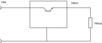
Homemade reobass will get rid of home computer noise, left overnight to download files. During the day, the computer seems to work quietly, but at night, it hums like an airplane. Just during the day computer noise is blocked by background sounds. At night the background disappears and computer noise turns into an annoying hum that interferes with sleep. And the point here is not that old ones need to be cleaned or replaced coolers for new branded brands and so on. No, the point here is that any clean, even the coolest coolers with full power will produce significant noise in the silence of the night.
speed controller
into the open circuit +12V, as shown in the figure. Attention! If your fan has 4 terminals, and their colors are: black, yellow, green and blue (for these, the plus power is supplied via the yellow wire), then the regulator is connected to the gap in the yellow wire.
A ready-made, assembled fan speed controller is installed in any convenient place on the system unit, for example, in the front of a plug in a five-inch bay, or in the back of a plug for expansion cards. To do this, drill a hole of the required diameter for the variable resistor you are using, then it is inserted into it and tightened with the special nut that comes with it. You can put a suitable handle on the axis of the variable resistor, for example from old Soviet equipment.
It is worth noting that if the transistor in your regulator gets very hot (for example, if the power consumption of a cooler fan is high or if several fans are connected through it at once), then it should be installed on a small radiator. The radiator can be a piece of aluminum or copper plate 2 - 3 mm thick, 3 cm long and 2 cm wide. But as practice has shown, if a regular computer fan with a current consumption of 0.1 - 0.2 A is connected to the regulator, then there is no need for a radiator, since The transistor heats up very little.
- Simple scheme
- With temperature sensor
- To reduce noise
- Video
How it works?
The information described below is valid for most schemes. Letter designations will be taken in accordance with the first circuit of the thyristor regulator
A thyristor power regulator, the operating principle of which is based on phase control of the voltage value, also changes the power. This principle lies in the fact that under normal conditions the load is affected by the alternating voltage of the household network, changing according to a sinusoidal law. Above, when describing the operating principle of a thyristor, it was said that each thyristor operates in one direction, that is, it controls its own half-wave from a sine wave. What does it mean?
If you periodically connect a load using a thyristor at a strictly defined moment, the value of the effective voltage will be lower, since part of the voltage (the effective value that “falls” on the load) will be less than the mains voltage. This phenomenon is illustrated in the graph.
The shaded area is the area of stress that is under load. The letter “a” on the horizontal axis indicates the opening moment of the thyristor. When the positive half-wave ends and the period with the negative half-wave begins, one of the thyristors closes, and at the same moment the second thyristor opens.
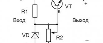
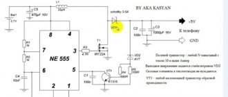
Fan speed controller - simple diagram
The circuit proposed below provides simple adjustment of fan speed without speed control. The device uses domestic transistors KT361 and KT814. Structurally, the board is placed directly in the power supply, on one of the radiators. It has additional seats for connecting a second sensor (external) and the ability to add a zener diode, which limits the minimum voltage supplied to the fan.
List of required radioelements:
- 2 bipolar transistors - KT361A and KT814A.
- Zener diode - 1N4736A (6.8V).
- Diode.
- Electrolytic capacitor - 10 µF.
- 8 resistors - 1x300 Ohm, 1x1 kOhm, 1x560 Ohm, 2x68 kOhm, 1x2 kOhm, 1x1 kOhm, 1x1 MOhm.
- Thermistor - 10 kOhm
- Fan.
Fan speed controller board:
Photo of the finished fan speed controller:
Selecting a device
In order to select an effective regulator, it is necessary to take into account the characteristics of the device and its intended purpose.
Vector controllers are common for commutator motors, but scalar controllers are more reliable. An important selection criterion is power. It must correspond to what is permissible on the unit used
It is better to exceed for safe operation of the system. The voltage must be within acceptable wide ranges. The main purpose of the regulator is to convert frequency, so this aspect must be selected according to the technical requirements. You also need to pay attention to the service life, dimensions, number of inputs.
Fan controller with temperature sensor
As is known, the fan in AT-format computer power supplies rotates at a constant frequency, regardless of the temperature of the high-voltage transistor housings. However, the power supply does not always deliver maximum power to the load. The peak of power consumption occurs when the computer is turned on, and the following maximums occur during intensive disk traffic.
- How to make a controlled 1.2-35 V regulator board
If we also take into account the fact that the power of the power supply is usually selected with a reserve even for maximum power consumption, it is not difficult to come to the conclusion that most of the time it is underloaded and the forced cooling of the heat sink of high-voltage transistors is excessive. In other words, the fan wastes cubic meters of air, creating quite a lot of noise and sucking dust inside the case.
You can reduce fan wear and reduce the overall noise level generated by the computer by using an automatic fan speed controller, the diagram of which is shown in the figure. The temperature sensor is germanium diodes VD1–VD4, connected in the opposite direction to the base circuit of the composite transistor VT1VT2. The choice of diodes as a sensor is due to the fact that the dependence of the reverse current on temperature is more pronounced than the similar dependence of the resistance of thermistors. In addition, the glass housing of these diodes allows you to do without any dielectric spacers when installing power supply transistors on the heat sink.
- 2 bipolar transistors (VT1, VT2) - KT315B and KT815A, respectively.
- 4 diodes (VD1-VD4) - D9B.
- 2 resistors (R1, R2) - 2 kOhm and 75 kOhm (selection), respectively.
- Fan (M1).
Resistor R1 eliminates the possibility of failure of transistors VT1, VT2 in the event of thermal breakdown of the diodes (for example, when the fan motor is jammed). Its resistance is selected based on the maximum permissible value of the base current VT1. Resistor R2 determines the response threshold of the regulator.
It should be noted that the number of diodes of the temperature sensor depends on the static current transfer coefficient of the composite transistor VT1, VT2. If, with the resistance of resistor R2 indicated in the diagram, room temperature and the power on, the fan impeller is motionless, the number of diodes should be increased.
Easy adjustment of electric heating power
The closed or open position of the contacts depends on whether voltage is applied or removed from its control coil. It turns out that in order to assemble the automation, we must supply control signals (voltage) to the terminals of these same coils through some other elements.
The coil has two contacts A1, A2.
When purchasing, pay attention that starters can come with 380V and 220V coils. It's better to take the last option
In this case, you directly connect the neutral conductor to one of the contacts, and install microswitch buttons into the gap of the second.
What are they needed for? Thanks to them, you have the opportunity to turn on 1,2 or 3 heating elements alternately, thereby increasing or decreasing the heating power.
For example, the temperature outside the window is -5C. You press one button and start up just one heating element with a power of 2 kW. The frost hit -25C, press all three buttons and increase the power three times.
In this case, the number of heating stages will depend on the rated power of each heating element. If they are all 2 kW, that’s only three steps.
But if one is 2 kW, the second is 3 kW, and the third is 4 kW, then the number of stages automatically increases to seven!
Everything will depend on which phases (heating elements) are connected and in what sequence.
individually 2kW – 3kW – 4kW
together 2kw+3kw+4kw
separately 2kW+3kW
separately 2kW+4kW
separately 3kW+4kW
The current in the coil control circuits is very small (several milliamps). Accordingly, there is no need to install full-fledged switches here.
All these three microswitches must be supplied with one phase. Let's say phase C. Take it from the lower contacts of the input circuit breaker.
It is from this point that the entire further automation scheme begins.
Fan speed control circuit to reduce noise
Unlike the circuit, which slows down the fan speed after the start (for sure start of the fan), this circuit will increase the efficiency of the fan by increasing the speed when the sensor temperature rises. The circuit also reduces fan noise and extends its service life.
Parts required for assembly:
- Bipolar transistor (VT1) - KT815A.
- Electrolytic capacitor (C1) - 200 µF/16V.
- Variable resistor (R1) - Rt/5.
- Thermistor (Rt) - 10–30 kOhm.
- Resistor (R2) - 3–5 kOhm (1 W).
The adjustment is made before attaching the temperature sensor to the radiator. By rotating R1, we make the fan stop. Then, by rotating in the opposite direction, we ensure that it starts up when we squeeze the thermistor between our fingers (36 degrees).
If your fan sometimes does not start even with strong heating (bring a soldering iron to it), then you need to add a chain C1, R2. Then we set R1 so that the fan is guaranteed to start when voltage is applied to a cold power supply. A few seconds after charging the capacitor, the speed dropped, but the fan did not stop completely. Now we fix the sensor and check how it all rotates during real operation.
Rt - any thermistor with negative TKE, for example, MMT1 with a nominal value of 10–30 kOhm. The thermistor is attached (glued) through a thin insulating gasket (preferably mica) to the radiator of high-voltage transistors (or to one of them).
Video about assembling the fan speed controller:
The noise produced by fans in modern computers is quite loud, and this is a fairly common problem among users. A fan or cooler speed controller can help reduce the noise emitted by computer fans of the system unit. There are various controllers on sale that have a variety of additional functions and capabilities (temperature control, automatic speed control, etc.).
The mechanism of interaction between the dimmer and the transformer
How a dimmer works is easy to understand if you look closely at the constitutive features of the circular mechanism
According to the power supply scheme, it is important that it consumes minimal power and efficiency is high. Functional:
- supply of operating voltage;
- charging the capacitor;
- displacement of working phases;
- receiving a voltage signal;
- semiconductor discovery; reduction of resistance;
- appearance of light;
- current distribution;
- voltage offset - at a frequency of about 100 Hz it will flicker.
The user can regulate the voltage supply. He selects the indicators himself, smoothly moving the dimmer head. The connection is made through light bulbs in two places at the bottom of the structure.
speed controller
into the open circuit +12V, as shown in the figure. Attention! If your fan has 4 terminals, and their colors are: black, yellow, green and blue (for these, the plus power is supplied via the yellow wire), then the regulator is connected to the gap in the yellow wire.
A ready-made, assembled fan speed controller is installed in any convenient place on the system unit, for example, in the front of a plug in a five-inch bay, or in the back of a plug for expansion cards. To do this, drill a hole of the required diameter for the variable resistor you are using, then it is inserted into it and tightened with the special nut that comes with it. You can put a suitable handle on the axis of the variable resistor, for example from old Soviet equipment.
It is worth noting that if the transistor in your regulator gets very hot (for example, if the power consumption of a cooler fan is high or if several fans are connected through it at once), then it should be installed on a small radiator. The radiator can be a piece of aluminum or copper plate 2 - 3 mm thick, 3 cm long and 2 cm wide. But as practice has shown, if a regular computer fan with a current consumption of 0.1 - 0.2 A is connected to the regulator, then there is no need for a radiator, since The transistor heats up very little.
Controller connection rules
Let's figure out how to connect the regulator depending on its type.
Let's start with the most common types - triac and thyristor. Their installation is very simple. If there is the necessary diagram, anyone can navigate it (see below). Regulation is carried out by the control unit. Each model has its own power - it cannot withstand more voltage.
Connection diagram for triac and thyristor controllers
The second type is transformer. The input voltage is 230 Volts. The winding has a number of branches. To reduce the voltage, you need to connect a load to them. Once the voltage has decreased, energy consumption becomes lower. The switch allows you to connect the motor to the desired section of the winding, and then the voltage changes.
Transformer type connection diagram
If we consider models of the electronic principle of operation, the connection diagram will be different. Here, using pulse simulation, the voltage changes smoothly. The longer the pulses and the shorter the pause time, the higher the voltage, and vice versa - short pulses with long pauses indicate low voltage.
Diagram of electronic operating principle models
If the fan has a timer, then it works on a different principle - the lighting turns on along with the fan. After turning off the light, the device continues to work for a certain time. The diagram and example of connecting an exhaust fan with a timer is shown in the picture below.
Exhaust fan connection diagram with timer
A power cable (FZN) is pulled into the distribution box, and a two-core cable is run from it to the switch. There is a triple wire to the light source, and 4 wires are connected to the fan. Now you need to make their connection in the power box.
Take a blue wire that goes to the lamp, and a blue wire that goes to the N-contact. They are peeled and twisted together. Next, you need to take and strip the phase wire, brown from the switch and brown from the exhaust fan (L-contact) and twist these 3 wires together.
Next, we take the yellow one for the supply, the yellow one from the lamp, the yellow one from the fan with a grounding contact - we clean it and twist it.
The brown one from the lamp, the additional one from the LT contact (timer power supply), the blue two-wire one going to the switch, are twisted together.
The next step is soldering and crimping the wires, insulating them and placing them in a box. There are many connection options, but the one described is the most popular and time-tested. The final stage is applying voltage and checking the functionality of the circuit.
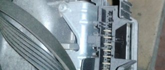
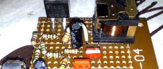
Assembling a reobass for a computer - diagrams and their description
Computer power cable
- We cut out a piece of the required size from foil PCB and draw tracks with a marker for disks.
- Pour ferric chloride (FeCl3) into a glass jar, dilute it with water (H2O) and throw the board into it.
- Stir occasionally and wait until it disappears.
- After weeding, wipe the tracks on the board with alcohol and drill with a 0.8–1 mm drill. You can use a breadboard, but it will be easier to get confused. Next we solder the parts.
- We take the CD-ROM case and stuff it all in there.
- We drill holes (if necessary) in the back wall and bring the male-type Molex and spring terminals out.
- Next you need to solder the wires. We lead the ground to the circuits of the hard drive loading indicators and to all the black contacts of the spring terminals. +5 only for the hard drive loading indicator. +12 to all middle contacts of switches. And we bring the wires from the + circuit to all the red contacts of the spring terminals.
- We put everything in its place. We connect MOLEX and fans.