Three things prompted me to write this article. Firstly, for the first time in my 10-year career, I attended Computex, which takes place every summer in Taipei. Regular readers of the many reports published on our website probably noticed that at this event a huge amount of all kinds of computer equipment equipped with backlight was presented. The stands of large and small manufacturers were literally bursting with a cluster of colorful and bright system units, components and peripherals.
Secondly, at Computex 2022 many assemblies in the Quadstellar case were presented, which will be discussed below. That is why, when Deepcool invited us to test their device, an attempt was made not just to review the case, but to try to independently “make” a system with a large number of components equipped with RGB backlighting - and at the same time identify various features and nuances that can faced by a novice user.
Thirdly, it must be recognized: every day more and more components equipped with RGB backlight appear on the computer market. To prove this statement you don’t have to go far - just visit 3DNews.ru every day.
At the same time, among our readers there are skeptics who believe that backlighting and other modding elements in a computer are useless tinsel, because the main criteria when selecting components are performance, reliability and functionality. Indeed, these qualities are at the forefront of any PC and there is no point in assembling a system with RGB backlighting just for the sake of backlighting alone. Let's not divide everything that happens in our lives only into white and black: in this article we will show that a computer with RGB backlighting can be productive, reliable, functional, and, finally, beautiful.
Why do you need illumination of the area near the computer?
There are several reasons to organize lighting for the PC user’s work area:
- Taking care of your eyes. Looking at a bright display in a dark room is harmful to the organs of vision, it causes overstrain.
- The need to take notes as you work, read books and magazines.
- Having snacks at the computer, drinking hot drinks. It is inconvenient to do this in the dark; you might knock over the cup.
Illumination inside the system unit with a transparent cover, in addition to solving practical problems, gives it an attractive, futuristic look. With its help it is easy to make your PC special.
Why do this
If you need to illuminate the space around your computer, you shouldn’t waste money and take up space with a lamp. You can get by with a piece of LED strip and the result will be no worse than the finished version. This solution is also good because it consumes a minimum of energy, this is the most economical backlight today.
Lighting using LED strip serves different purposes. Most often used like this:
- To illuminate the work area near the computer. In this case, the tape needs to be placed higher so that it covers the entire table.
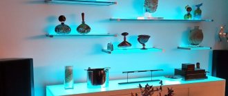
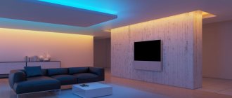
- Soft illumination of the space around the computer. It looks especially impressive if the monitor is mounted on the wall and the LEDs are located in the back. In this case, it is better to use a single-color option.
- System unit backlight. If the inside is top quality and one of the walls is transparent, you can highlight the space around the perimeter. Or replace one partition with plexiglass yourself and decorate your computer effectively.
- Illuminated keyboard for comfortable operation. There is not enough light from the monitor, so you can add a small piece of tape and illuminate the space without creating excess light.
- Decorative lighting for a table or interior elements located near the computer. For example, you can glue LEDs along the end of the tabletop or in its lower part. Or make a strip on the wall so as not to turn on the general light while playing games or watching movies.
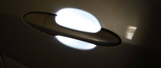
Option for lighting the back of the monitor.
This method is good because to illuminate the space around the computer you do not need to stretch wires, of which there are already so many. And to connect, you don’t need an outlet, which is also often a problem, since you need to power many devices. An additional advantage is the long service life; the backlight works normally for at least 10 years.
How does LED strip work and what are its properties?
The product is a flexible polymer-based board. There are 2 conductors attached to it and diodes connected between them, which emit light when current flows.
Advantages of the device:
- Economical. For 1 W of power consumption, the LED strip produces a luminous flux of 90-120 lm. For fluorescent and halogen lamps this figure is 25-50 and 15-20 lm, respectively.
- Durability. The lifespan of the diodes is 50 thousand hours if they are not subjected to overheating and voltage overloads.
- Simple and quick installation. The tape has an adhesive layer. Thanks to its flexibility, it can be mounted on a curved or broken surface.
- Low heat generation.
- Compactness. A small piece of tape is placed in the system unit.
If the computer is in the bedroom, the product can be fixed on the back of the monitor or under the table. Lighting with reflected rays will allow you to read texts, but will not disturb the sleep of other family members.
Popular devices are in the form of flexible PVC tubes with diodes inside. Their walls have a matte transparency, so the lamp looks like a neon lamp.
Diodes only allow current to pass in one direction. Accordingly, a constant voltage is applied to the tape.
Rules for connecting to the network
LED strips are designed for a potential difference of 12 V, models with the number of diodes 240 pcs./p. m - 24 V.
There are 2 ways to connect the light source.
Without power supply
To connect to a 220 V network, the parallel connection of the diodes is changed to a serial one. 220 is 18.33 times greater than 12, which means that it is necessary to connect 19 diodes or their parallel groups in series. Then the voltage drop across each of them will be 11.5 V.
The tape is cut according to special marks. If you cut it arbitrarily, the performance of the product will be impaired. The number of LEDs between the marks differs for different models, the minimum number is 3.
Thus, to connect to a 220 V network you will need at least 57 elements. When assembling the lighting device, polarity is observed: LED groups are connected by contacts of the same name.
To convert alternating voltage to direct voltage, a diode bridge is assembled. To smooth out ripples, a 300 V capacitor with a capacity of 5-10 mF is included in the circuit.
LED strips with fittings are available for sale, ready for use in a ~220 V network.
Via power supply
The lighting device must be connected to the output terminals of the converter, observing the polarity. They are guided by the color of the wire insulation: black or white – “minus”, others (mostly red) – “plus”. The switch and dimmer are installed in the gap of any wire.
The following power supplies are suitable:
- standard, made specifically for LED strip;
- from a laptop;
- computer (for backlighting in the system unit);
- phone charger.
The current consumed by the tape cannot exceed the rated value for this power supply. This value depends on the number of diodes and their type. The table will help you perform the calculation:
| LED type | LED density per 1 linear meter of strip | Current (A) per tape length | |||
| 1m | 2 m | 3m | 4 m | ||
| SMD3528 | 30 | 0.2 | 0.4 | 0.6 | 0.8 |
| 60 | 0.4 | 0.8 | 1.2 | 1.6 | |
| 120 | 0.8 | 1.6 | 2.4 | 3.2 | |
| SMD5050 | 30 | 0.6 | 1.2 | 1.8 | 2.4 |
| 60 | 1.2 | 2.4 | 3.6 | 4.8 | |
The wires are connected to the contact pads by soldering or using special connectors.
Backlight control
All described methods for connecting the backlight assume that it will light up when the PC is turned on. If you use a USB connector, you can disconnect the tape at any time, but this method cannot be called convenient. Let's look at the main ways to control the backlight:
- you can add a regular switch to the circuit in the form of a button or switch (as in a sconce) and place it in a convenient place;
- if you need to control RGB lighting connected to the motherboard, a controller is included in the circuit that allows you to program the color scheme. It is not placed in plain sight, but in a place where it does not overheat;
- to adjust the brightness of the glow, use a dimmer, which also allows you to adjust the contrast and color temperature of the diodes, and turn the tape off/on;
- Some motherboard models come with software that allows you to control the operation of the LED backlight (brightness, contrast, shades and many other effects) through the program.
As you can see, organizing lighting at your workplace is not difficult. The main thing is to calculate everything correctly, and during installation follow the instructions described.
Connection diagram for a conventional LED strip
Electrical power is supplied through the computer's power supply's 4-pin Molex connector.
It includes wires:
- Black – “ground” (Gnd or COM).
- Yellow – voltage +12 V.
- Red – voltage +5 V.
They operate in this order:
- Cut off the connector.
- Strip the yellow wire and 1 black wire, the rest are insulated.
- The conductors and contact pads of the tape are connected by soldering. The yellow wire is connected to the “plus”, the black wire to the “minus”.
- Insulate the connection with heat shrink tubing.
In order not to cut off the connector, you can purchase a mating part for it (plug) as part of a Molex-SATA adapter. It is designed to power newer hard drives with a serial data bus. The SATA connector is cut off, and a tape is connected to the freed wires.
Next, the plug is inserted into the Molex connector. The maximum current for it is 20 A, but taking into account the presence of other devices (hard drive, DVD drive, etc.), it is not recommended to connect a load of more than 5 A (preferably up to 4 A).
You can implement a circuit with stepwise brightness adjustment. You will need a 2-position switch with a remote control function.
One of its contacts is connected to the “minus” of the tape, the other 2 are connected to the red (+5 V) and black wires of the connector. When the regulator is moved to the first position, a potential difference of 12-5 = 7 V is applied to the diodes, and they burn at half power.
You can connect a 24 V strip to a free power supply from a PC. The connector for power supply to the motherboard (MB-20 or MB-24) is used.
A voltage of -12 V is supplied to one of its contacts. A wire in blue insulation is suitable for it. In MB-20 it is located under the 12th number, in MB-24 – under the 14th. The “minus” of the tape is connected to this contact, the “plus” to the yellow wire (+12 V). As a result, the potential difference across the diodes will be 24 V. The maximum current when connected to the MB connector is 1 A.
To start the unit without connecting to the motherboard, install a jumper on the PS ON (green wire) and Gnd (black) contacts on the MB connector.
⇡#Assembling the system in the Deepcool Quadstellar case and connecting the backlight
Now that we have decided on the choice of components, all that remains is to put everything together. The Deepcool Quadstellar is an unusual case, but even when working with such a device, you just need to follow all the steps described in this article. In fact, we are dealing with a Full Tower case, made in a futuristic style. Just in case, below are the technical specifications of the Deepcool Quadstellar.
| Technical characteristics of Deepcool Quadstellar | |
| Type | Full Tower |
| Dimensions (H × W × D), mm | 483 × 493 × 538 mm |
| Weight, kg | 14,5 |
| Color | Black |
| Material | Plastic, aluminum, tempered glass |
| Standard cooling system | 5 × 120mm fans |
| Drive bays | Up to 13 2.5" or up to 8 3.5" |
| Expansion slots, pcs. | 8+6 |
| Motherboard Compatibility | E-ATX (305 × 330 mm), ATX, mATX, mini-ITX |
| I/O ports | 2 × USB 3.0 Type A 2 × 3.5 mm jack |
| Power supply support | ATX PS2 |
| Maximum length of power supply, mm | 300 mm |
| Maximum height of CPU cooler, mm | 110 mm |
| Maximum video card length, mm | 380 mm |
| Price | 27,000 rubles |
The body chassis is entirely made of aluminum. The visors on the front panel are made of glossy opaque plastic, and the four removable windows are made of tinted tempered glass. The windows are attached to the body using magnets. By the way, in this way, without disassembling the entire device, it is very easy to clean the components from dust.
The front panel of the case personally reminds me of a blooming flower. By the way, the “petals” of the Deepcool Quadstellar open when turned on, and this action looks very fascinating. Dust collection filters are “hidden” behind the blades in the housing, which can always be removed and cleaned. And behind the filters are four 120 mm Deepcool TF120 fans operating as a blower. They are not backlit, by the way. The minimum rotation speed of the Carlsons is 500 rpm, and the maximum is 1500 rpm. Another fan - the fifth (exactly the same TF120) - works for exhaust and is installed in the rear part of the section with storage baskets. It is not possible to install other larger case fans (for example, 140 mm) in these seats.
As you can see from the photos (and also from the name), the interior of the Deepcool Quadstellar is divided into four sections. If you look at the hut case from the back, you will see that the upper left compartment is intended for installing video cards - graphics adapters up to 380 mm in length are supported. The section will accommodate video cards of any thickness. If you get another flexible cable and a remote PCI Express x16 connector, you can even install two video cards there. However, I don’t recommend doing this - two video cards, even with a case fan running on air, will be a bit cramped in such an improvised “bunker”. If you do not use a flexible cable, then the video card can be installed directly into the expansion slot of the motherboard. Usually unused top section by modders
.
Drives are installed in the upper right compartment. Deepcool Quadstellar has eight bays for installing 3.5-inch hard drives and two more bays for installing 2.5-inch storage devices. One of these pockets can accommodate a backlit SSD. Just below is the GamerStorm inscription - it is also highlighted and can also be configured in the QuadStellar software.
I note that the cages for 3.5-inch HDDs are equipped with rubber gaskets. Yes, you will have to work with a screwdriver to screw in eight drives at once. Unfortunately, if you get rid of all the baskets, then, alas, you won’t be able to use the empty upper compartment of the case in any other way.
The power supply is installed in the lower right section. Deepcool Quadstellar supports sources up to 300mm in length. I’ll note right away: our “spaceship” has plenty of free space - so it’s not at all surprising that so many colorful projects with custom CVOs and lighting, created on the basis of this case, were presented at Computex. And yes, a backlit power supply will look quite harmonious in Deepcool Quadstellar. It's a pity that I didn't have such a model at hand.
The lower left section houses the motherboard. The case supports installation of devices of all popular form factors, including E-ATX. Just keep in mind that a large board will block the holes for cable routing.
At the beginning of the article, I noted that the front panel of the Deepcool Quadstellar is equipped with backlighting. “The Life-Giving Cross” is divided into four zones, which are configured separately - I will talk about this later. The Gamer Storm logo is also illuminated, and the rectangular diamond shape is also the power key. On the upper left side of the case there are two USB 3.1 Gen1 ports, as well as 3.5 mm jacks for connecting headphones and a microphone.
The case came with a colorful and detailed assembly manual, as well as all the necessary mounting tools, including additional adapters for connecting fans and lighting. It’s convenient that all the screws are put into bags and labeled.
In order to begin assembling the PC, it is necessary to partially disassemble the case, namely, remove the four metal walls from the compartments. After this, I suggest starting the assembly by installing the water cooling system, motherboard and power supply.
The best place to start is by installing a processor cooler. Look, the maximum CO height in Deepcool Quadstellar should not exceed 110 mm, so with such a case it makes sense to use a liquid cooling system. The device supports the installation of one 360 mm and one 240 mm radiators. In the first case, the SVO element is attached to a plate attached to the front panel; in the second case - to the special slides provided at the bottom of the compartment for installing the motherboard. Larger radiators will not fit into the case. The grill under the skid is equipped with a removable dust filter.
To write this article, my choice fell on a maintenance-free SVO with a 240 mm long radiator. First, I removed the metal plate, unscrewed the existing Deepcool TF 120 fan and attached the dropsy radiator to it. I then secured the plate back to the front panel using two screws and three thumbs. After this procedure, you can begin installing the motherboard, but before that, do not forget to secure the central processor and part of the LSS fastening mechanism in the socket.
Our system uses the MSI Z370 GODLIKE GAMING motherboard; it is made in the E-ATX form factor. In general, there is nothing critical about this, but the PCB blocked the holes for routing the power supply cables. After installing the motherboard, we attach the water block to the central processor and proceed to install the power supply.
There will definitely be no problems with installing the power supply. There is plenty of free space behind the barrier wall in Deepcool Quadstellar. At the same time, the chassis is designed so that the length of all main power supply cables is sufficient to connect the motherboard, video card and storage devices.
After installing the power supply, I began connecting all the wires, including the connectors from the I/O panel of the case.
By default, all Deepcool Quadstellar case fans are already connected to the control unit. There is an information plate next to it, which will definitely come in handy if you want to somehow reconnect the impellers or install other blowers. Personally, I didn’t touch anything, but simply reconnected the existing wires more carefully.
By the way, a thermocouple comes from the control unit, which can be attached to any part of the housing. The temperature reading from this sensor will be displayed in the QuadStellar mobile app.
After installing the SVO, motherboard and power supply, as well as connecting the case controls and interfaces, all that remains is to connect the drives, video card and, in fact, the backlight.
There will be no problems with installing hard drives: we fix the HDD in the basket and connect the wires to it. We install the video card last. I decided to place it in a separate section - this makes the assembly look much more brutal.
Our assembly has five elements equipped with RGB backlighting. Everything is clear with the motherboard, video card and RAM - there is no need to connect any wires for RGB to work. Therefore, all that remains is to connect the backlit fans and the tape.
At the bottom of the MSI Z370 GODLIKE GAMING there are two headers for connecting tapes: JRGB for 12V tape and JRAINBOW for connecting 5V addressable tape. I decided to install a pair of ENERMAX fans on the dropsy. In addition, they are fully compatible with Mystic Light technology. Placing the control controller was easy: double-sided adhesive tape is included, and the Deepcool Quadstellar has plenty of free space. The fans have their own proprietary connector with which they connect to the controller. The controller itself is connected to the JRGB connectors of the motherboard and the MOLEX power supply.
That's basically it. Included with the MSI Z370 GODLIKE GAMING was a splitter that allows you to connect two tapes to one JRGB connector at once. It is important to connect the tape correctly. For this purpose, there is an arrow on the connectors. If connected incorrectly, the RGB strip will simply burn out. The same goes for addressable 5V strips.
Finally, all that remains is to carefully secure all the wires and check that nothing is sticking out and spoiling the appearance.
That's it, now you can install the video card, connect it to the power supply and close the side walls. Deepcool Quadstellar is ready for the first launch and subsequent backlight settings, although even without it the system already looks very, very attractive.
RGB strip connection and diagram
The product consists of diodes of 3 colors - red, green and blue. There are 4 contacts: 1 “plus” and 3 “minus”. An RGB controller is required for connection. On one side it has 2 contacts for connecting to a constant power source. On the other hand, there is also 1 “plus” and 3 “minuses” for each color.
For installation in a computer case, a controller with remote control capability is required. There are programmable models that change colors automatically according to a user-specified scenario.
Backlit PC case on Arduino and WS2812 with CPU and GPU temperature display
I am glad to welcome everyone again to the “U Samodelkina” website. I like to play computer games sometimes. Sometimes these are calm turn-based strategies like Heroes or XCOM, and sometimes furious action like DOOM. And, of course, I want my computer to look beautiful and interesting. There are many ways to achieve this, but today I will focus on instructions for adding backlight to the system unit. Just adding LEDs or glowing coolers is too simple and uninteresting. We will cover the inside of the system unit with LED strip made from WS2812 and install an Arduino or Attiny85 or ESP8266 to control the strip. It will be possible to run a bunch of effects, which will diversify the look of the system. A garland from a system unit is certainly cool, but it’s also somehow too simple and boring. Therefore, there will be other uses besides beauty. We will use the backlight to display the CPU and GPU temperatures. We will run a program on the computer, which in turn will take readings from the computer’s sensors and send them to the controller that controls the WS2812 tape.
- Arduino (any version) or ESP8266 or Attiny 85 - ws2812 tape or rings - USB-TTL for Arduino Pro mini or ESP8266 - ISP programmer for Attiny (you can use any Arduino instead) - Connecting wires - Molex connector, female - Soldering iron, solder, rosin - Straight hands and accuracy
That is, in a body made of monolithic polycarbonate, plexiglass or the like. Or something similar
Types of LED strips for connecting to a computer via USB
The USB connector has the following parameters:
- voltage – 5 V;
- rated current – 0.5 A.
The light source is connected through a converter that increases the voltage by 2.5 times. At the same time, the permissible current will decrease by the same factor - to 0.2 A.
Thus, 30 LEDs of the SMD 3528 type or 10 of the SMD 5050 type can be connected to the USB connector. The length of the strip depends on the density of the elements placed on it.
Cases with built-in lighting
If you are not going to buy a gaming PC with backlighting, then it is enough to buy yourself only a case with built-in lighting. They differ in price from regular cases, but this is compensated by the fact that all the elements are already factory-made, that is, if an unforeseen circumstance occurs, you can try to return the case under the warranty certificate (besides, if a person is not confident in his abilities, then it is better overpay for a backlit PC case). And if you decide to take a regular case and stuff it with tape and glue, then it will be much more difficult to return it. In any case, everyone decides for themselves which housing to take and whether it is worth framing it with LED strip.
Connection diagram for backlight via USB
The connector has 4 pins. The second and third are used for data transmission, the first and fourth are for power supply. Dismountable plugs for the connector are sold in computer stores.
The LED strip is connected through a step-up voltage converter, which produces 12 V at the output. Such devices are also commercially available, but the circuit is easy to assemble with your own hands.
The converted voltage is constant, so it cannot be increased by a transformer. Instead, they use the LM2577 chip, which is a pulse width modulation (PWM) controller. Other radio components will also be required.
A USB plug is soldered to the input terminals of the converter, having first checked the polarity of the contacts in the connector with a tester. Connect poles of the same name. An LED strip is connected to the opposite side of the device.
Materials and tools required for work
Connecting LED backlighting is not fundamentally difficult and can easily be done with your own hands. To do this, you need to have some skills in working with a soldering iron and minimal knowledge. Tools you will need:
- LED strip for computer;
- 12V power supply;
- soldering iron and solder;
- scissors;
- connecting wires;
- nippers or side cutters.
The most necessary tools are listed, but other equipment may be needed.
How to make a backlight for a PC with your own hands?
They operate in the following order:
- Based on special marks, a fragment of a given length is cut from the tape,
- Treat the contact pads (lamellas) on it with alcohol.
- Using a puller or a utility knife, remove the ends of the wires from the insulation to a length of 5 mm.
- The exposed area is twisted into a tourniquet.
- Dip the stripped ends of the wires into rosin.
- Flux is applied to the contact pads of the LED strip using a toothpick.
- Take a small dose of solder with a heated soldering iron tip and transfer it to the lamella. To avoid burning it out, the contact time should be limited to 1 second.
- Solder tubercles are formed similarly on other contact pads of the connected tape.
- Brown deposits from the flux are removed with a napkin. If it has time to harden, this will require alcohol.
- Use wire cutters to shorten the bare ends of the wires so that they are equal in length to the lamellas. Otherwise, a short circuit may occur when the wires are bent.
- The core is placed on a tubercle of solder and pressed into it with a heated soldering iron. Contact duration is limited to 1 second.
- Before the solder hardens, ensure that the connection remains motionless. This takes a few seconds.
- Having soldered all the wires, clean the contact points from flux with a cloth soaked in alcohol.
- Place a heat shrink tube over the assembly and heat it.
- Cut off the SATA connector from the adapter.
- Strip the ends of the yellow and one black wires. The rest are trimmed and isolated.
- Heat shrink tubes are put on.
- Twist the wires from the LED strip and the connector in compliance with the polarity. Then the connection is soldered.
- Slide heat-shrinkable tubes over the contact points and heat them with a hair dryer, match or gas lighter.
- Insert the adapter plug into the Molex connector.
The RGB strip is connected in the same way. To avoid confusion, it is recommended to solder wires in insulation of different colors to the “cons”. Next, connect the cores from the Molex-SATA adapter to the RGB controller. On the other hand, wires from the LED module are connected to it.
The backlight assembled in this way lights up simultaneously with the computer startup. To be able to extinguish it during the day, a microswitch with a remote control function, for example, from a smartphone, is soldered into the gap of one of the wires.
The installation process is simplified if you purchase a piece of tape with wires already connected.
Main conclusions
PC backlight allows you to decorate your computer and reduce the negative impact of a bright screen on your eyes. The main task is to connect the power supply to the tape, for which there are several options:
- from the network via a power supply;
- from the network without a power supply (via a diode bridge);
- from the computer power supply;
- via USB (relevant for laptops).
During installation and connection, the main task will be to maintain the polarity of the connection and protect the tape from overheating. The user is not required to have deep knowledge of electronics, just basic school knowledge and some soldering iron skills. Please share your PC lighting options in the comments.