Model selection
Firstly, it is immediately worth noting that building an airplane, as other craftsmen do, is not entirely realistic. The thing is that each person has an individual style of piloting, because of which you cannot rely on other people’s experience when choosing a model. Secondly, many novice designers are inspired to create after they see quite beautiful and elegant models in the sky. Based only on the appearance of the aircraft is extremely bad. The main criterion for choosing a model should be the purpose of its construction and future use, and not the aesthetic component.
Choosing the right model is also important because it can only be used for the purposes for which it is intended. Let's say building an airplane as a means of air tourism is one thing. But after its completion and operation, you can find that a person is much closer to a regular flight to a picnic somewhere in the mountains, for example, and this will require a completely different model. All this suggests that before moving on to any practical part, it is necessary to fully consider and clearly define for what purpose the aircraft will be used.
Naturally, before moving on to construction, it is necessary to carry out some more preparatory work. It is necessary to conduct a full analysis of the design of the future aircraft. If someone has already implemented such a design, then it is worth contacting this master and inquiring about the success of the aircraft. It is also important to remember that if you choose a model in which the parts and assemblies are of an outdated type, then purchasing them and organizing delivery, if necessary, is much more difficult and expensive. Parts for models that are in demand at a given time will be more readily available.
FLYING JUNK
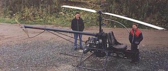
But Andrey Sarkisyan from Pyatigorsk was able to lift himself off the ground by one and a half meters in his helicopter. It doesn't matter that this device landed on its right side. A professional singer and musician, he works part-time in local restaurants in the evenings. I became interested in designing unique aircraft eight years ago. During this time I assembled four helicopters.
“Only one flew, but then I had to sell its engine because I needed funds,” admits Andrey.
Engines from Izh and Java motorcycles, large homemade machines and machines for cutting metal, and even a bushing from the Mi-2 tail rotor - in general, a pile of metal, iron, plastic, and material incomprehensible to ordinary people filled the yard, garage, and basement of the master.
In order to fly on aircraft of his own design, Sargsyan is trying to get a pilot’s license.
Time spent
How to build an airplane? Moving on to the practical part of this issue, it is very important to note that this process is very lengthy. It will take a huge amount of time and effort, and therefore you need to be sure that these two components are available in abundance before you start buying parts and other things.
Experts recommend breaking down such a labor-intensive task as building an airplane into a large number of small tasks. In this case, constant progress in manufacturing will be visible. Working on each task will require much more time, and each successful completion of the work will mean getting closer to the main goal. If you do not break this voluminous task into small parts, then at some point it may seem that stagnation has occurred and progress has stopped. Because of this, many people also give up the idea of assembling an airplane with their own hands.
If the process was correctly divided into parts, then a week you will have to allocate from 15 to 20 hours to complete the assigned tasks. With such an investment of time, it will be possible to build an aircraft in an acceptable time. If you spend less time per week, the process can drag on for a huge period of time.
How to build your own plane with your own superconductor and liquid nitrogen engine
Hint: keep everything small.
Introduction
Hi all. By training, I am an engineer for the operation of aircraft and aircraft engines, but in this article I will describe how I made a small electric motor using superconductors, and therefore please take my introduction as an excuse for the fact that I do not have sufficient competence and experience in the development and manufacture of electric motors , but still I did it. Therefore, dear experts, specialists, professionals and analysts, please make concessions for the amateur, and please provide all criticism and evidence of your rightness in the form of solutions made with your own hands.
Start
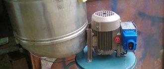
It so happened that in the spring of 2022 I started working as an engineer at SuperOx. I took part in the development of an electric motor based on superconductors (Photo). At first the work was interesting and sometimes dusty mixed with shavings from various materials. So many problems were solved :). Six months later, I realized that the path to a full-fledged aircraft with a superconductor engine would be long and difficult. Then the idea was born to make your own engine, put it on a small drone or radio-controlled plane and make at least one flight.
For reference. When I first learned about this company, I knew what a superconductor was, but I did not imagine that the production of such a product existed in the Russian Federation. It was really nice that such productions exist and are developing.
In the process of working and communicating with colleagues, I learned all sorts of subtleties and features of the use of superconductors. As knowledge was acquired, the engine design changed and adapted.
Somewhere in January 2022, a feeling appeared that if you don’t start doing anything, the moment might be lost forever (by the time you measure seven times, others will have been cut off long ago). At this point, I believed that I had accumulated a sufficient amount of knowledge to implement the entire project and began to work on my engine in parallel with my main work.
Initially, the idea was to develop a motor based on any available brushless electric motor for radio models, with an external permanent magnet rotor (outrunner).
An example of a brushless motor that can be found in many RC models.
But there were such obvious difficulties along the way as:
- the complexity of winding the windings on the stator. (The fact is that a superconductor wire is a metal tape with several layers of sputtering. The superconductor itself is a thin layer of ceramics. If the tape is bent too much, the superconductor layer can be damaged (
); - the stator iron (magnetic core) will be in liquid nitrogen. To cool it, an additional volume of nitrogen is required. Also, the stator iron will heat up when the electric motor is running and therefore nitrogen will evaporate more intensely;
- difficulty in removing the propeller shaft. It is necessary to provide thermal insulation between the rotor and the cryostator. It is also necessary to protect the rotor cavity from ice freezing and oxygen condensation;
- difficulty in switching windings. The conductor tape is thin and bends with some restrictions; soldering 24 contacts, trying to fit it into a small volume, should be difficult.
Diagram of an electric motor with a vertical layout and an external rotor.
It was not clear how to insulate the thermostat, how to avoid moisture freezing on the output shaft and bearings, and how to remove the propeller shaft.
Further thoughts were about the possibility of moving to brushless electric motors with an internal rotor with permanent magnets (inrunner). This idea looked more attractive. An important change is the decision to purge the rotor cavity with evaporating nitrogen. Due to this, with a constant flow of evaporating nitrogen, air along with moisture and oxygen should not penetrate inside. and therefore the bearings should not freeze. If air began to penetrate inside, the moisture from it would begin to condense on the surface of the inside of the rotor housing. The resulting ice could easily grab both the bearings and the rotor itself to the inner wall. But oxygen could be no less dangerous. The fact is that it condenses at a temperature of about -183 degrees Celsius (for comparison, nitrogen boils at -196.5 degrees Celsius). This leads to more intense evaporation of nitrogen when the energy of oxygen condensation is absorbed and cooled through a thin wall. And the very fact of the presence of liquid in the cavity where the rotor should rotate negatively affects the performance of the engine.
Diagram of a vertical electric motor with an internal rotor
This design had more advantages than the previous solution. However, the presence of a stator magnetic circuit also threatened to significantly increase labor intensity. The easiest way out of this situation is to get rid of the magnetic core. This is how the idea came to make a motor without a stator magnetic circuit (stator iron).
But the question still remained of how to increase the interaction of the magnetic flux between the stator coils and the permanent magnets of the rotor. A magnetic core is needed to transmit magnetic flux, but if the coil is brought as close as possible to the magnet (even better, the magnet is inside the coil), then perhaps this will compensate for the absence of a magnetic core.
And then the idea of a design with six distributed coils through one pole and a rotor with two poles gradually crystallized.
Plan A
In the top view it looked like this:
Diagram of an electric motor with six coils and a two-pole rotor.
Next, I started drawing the idea in 3d-cad T-Flex. By this time, it was possible to obtain several permanent magnets, the geometry of which determined the dimensions of the rotor and, as a consequence, the dimensions of the entire engine in the future.
So a design like this came about:
The first developed version of a magnetic system with superconductor coils.
I had to spend a lot of time developing the frame for the reel. The main problem was that the HTSC tape actually bends only in one plane, but allows some torsion. The combination of these two factors limits the trajectory along which this tape can be laid. But in the end, we managed to draw and print on a 3D printer the first prototype of the frame, onto which we were able to successfully attach the superconductor tape.
First printed superconductor tape winding frame
In addition to the frame, the rotor housing was also printed to accommodate the magnets, supports and the cylinder of the inner tube. Bearings and rotor axle were obtained.
To debug the engine, winding copper wire was wound onto the frames instead of HTSC tape. Each frame fit 4 turns (according to the recommendation of the person who did the engine calculations, 5 turns were needed).
Copper analog motor for checking the performance of the motor.
Everything was assembled, soldered and connected to a Castle Talon 90 ESC.
The first attempt to launch the copper analogue showed the obvious - low torque. At the initial moment, the controller begins to forcibly rotate the rotor without feedback. Once the feedback starts working, the controller can control the motor normally. But due to the absence of a magnetic circuit, feedback on the back EMF was difficult, and the low torque and moment of inertia of the rotor led to the fact that the rotor did not have time to spin up and made oscillatory turns around a certain equilibrium position.
But after the rotor was forced to spin, the engine started. And it began to rotate so wildly that I was afraid that the printed rotor would break into segments and the magnets would fly to the sides like shrapnel. Then we managed to measure 14 thousand rpm and noticed another feature: at high speeds the torque was greater than at low speeds. In the next experiment, I increased the input voltage from 12 V to 24 V and then the engine began to start on its own.
This preliminary success gave me inspiration. Believing that at high currents and speeds of the order of 10 thousand rpm, the engine power will be sufficient to rotate a propeller of small diameter and small pitch, I decided to make a horizontal engine with direct drive to the propeller.
But there was another unpleasant moment ahead. The fact is that in a vertical layout, the coils should have been in a heat-protective container (thermal mug from Ikea? :)), and in the center there should have been a thin-walled plastic cylinder. There should be a lid on top that directs the evaporating nitrogen into the cylindrical cavity of the rotor from where it is released into the atmosphere. This nitrogen gas, when released, does not allow atmospheric air to penetrate into the rotor cavity. The solution to this problem was found to be quite elegant in my opinion. A tube with holes was designed in the upper part of the vessel where the nitrogen is placed. This tube carried nitrogen vapor down along the front wall of the engine (engine with a pusher propeller) and exited in the area of the front support. Next, nitrogen gas passed through the front bearing, into the gap between the rotor and stator, and exited through the rear bearing.
Section of the engine in a vertical plane. The arrows indicate the direction of movement of nitrogen gas. (Housing insulation not shown)
The final recipe was as follows: the stator housing was a container with a central pipe to accommodate the rotor with supports. Six coils were placed around the central tube. The coils at the rear wall were switched between each other and three current leads, to which the copper wire terminals were connected. There, on the back wall, a nitrogen filler neck with a lid was attached. For the convenience of filling liquid nitrogen, the filler cap was replaced with a funnel.
The rotor consisted of an 8 mm stainless steel shaft (the shaft from a broken inkjet printer), onto which was pressed a plastic rotor housing, printed on a 3D printer, with magnets pressed into it. The propeller trunnion was attached to the end of the shaft.
The front rotor support was 3D printed from PLA plastic and a ceramic bearing was inserted into it. The rear support is also 3D printed and also with a bearing.
A set of frames with a wound superconductor and hand-turned brass current leads.
Everything was printed, glued with superglue, soldered, assembled, wrapped in cryogel, beautiful shiny tape and placed on a stand.
The engine is assembled and ready for the first freezing tests
The first launches showed the imperfection of the design. In principle, the engine began to rotate, but due to temperature deformations the bearings jammed and the rotor stopped. And given the low torque of the engine, it was not possible to start it 5 minutes after filling it with nitrogen. At some point, it seemed that the engine began to spin, but the shaft remained motionless. As it turned out, due to the low temperature, the plastic housing of the rotor shrank and, as a result, it fell apart in thin places.
Rotor housing in camber 
The rotor housing has been reprinted. After installing the rotor housing on the shaft and pressing in the magnets, the housing was covered with glass fiber on cyacrine.
Next was the struggle with the supports and bearings so that they would not jam right away (this is another half a week of research, modifications and testing). As a result, with a new rotor housing and new supports, the engine began to start stably and could provide sufficient thrust for a long time to fly an aircraft weighing approximately 3 kg (continuous operation time about 1 min).
It was decided to board the plane and fly.
At that time I had an empty glider of a Chinese Hunter aircraft with a wingspan of 1.8 m. I adapted it a little to install an engine. In particular, the rear fuselage was trimmed down to the wing attachment points in order to move the engine forward and thus make the aircraft easier to balance.
I also decided not to bother with the autopilot, but to install radio control. The final weight of the aircraft was around 3.6 kg.
I already had experience using a device of this mass, and using a conventional brushless electric motor with a rubber catapult, this plane took off and flew for a long time, and so I decided that the flight was possible (
).
I made an agreement with the pilot, went out into the field, and in the end the flight didn’t work out.
Several factors contributed to this failure:
- Large aircraft weight with low engine power. The rubber catapult accelerated the plane to its initial speed, but low engine power and a sharp climb immediately after takeoff led to a decrease in speed and, as a consequence, to the stalling and crash of the plane.
- Poor aerodynamics. The standard airframe fuselage was quite plump. Also, the protruding piece of the power frame to which the engine was attached, and two vertical planes in the rear part of the fuselage formed by the cut of the fuselage and the rear wall of the engine, do not add to the aerodynamics.
- There is another factor that could influence the operation of the engine in its own way. The fact is that the outside of the engine was covered with aluminum tape on a self-adhesive basis. And given the small distance between the rotor and the wall, alternating magnetic fields when the rotor rotates create a counter-EMF in a thin layer of foil. And with increasing speed, this effect only intensifies (demonstration of this effect using the example of oscillation of a permanent magnet over an aluminum plate).
The solutions were the following:
To reduce the weight of the aircraft, all parts were weighed, measured and a weight model of the aircraft was created. As a result, it was decided to move the engine even closer to the front of the aircraft. Remove two batteries with a total weight of 1000 g. Instead, one battery weighing approximately 300 g will be installed. To maintain balance, the battery must be moved forward by 150 mm and this required a new fuselage.
Weight model of the aircraft. Above is the old model, below is the model with a new fuselage and a new battery.
The new fuselage should also improve the aerodynamics of the aircraft.
After spending a few more days. The fuselage was designed and cut on a CNC machine. Covered with fiberglass and painted.
Manufacturing a new airframe on a CNC milling machine
Trying on the new fuselage.
Aircraft pre-assembly
The aluminum tape from the surface of the engine was removed.
In addition to the fuselage, strength frames for reinforcement and a stand for the aircraft with a new fuselage were cut out.
Airplane stand
Everything was collected and ready to fly again.
In the field, just before takeoff, an engine failure occurred. After several attempts to start the engine, I rang the motor windings and detected a break in one phase.
Sadness.
After disassembling the engine, it turned out that a crack had appeared in the inner pipe printed from plastic. As a result, the nitrogen level was much lower than necessary and the upper conductors were not cooled. As a result, when a large current is supplied, the uppermost conductor going to the current terminal burns out.
But the most important thing is that the body made of printed plastic could no longer be restored.
At this time, I did not have access to a 3D printer, but I did have a CNC milling machine. And so it was time for plan B.
Plan b"
It was decided to make the motor housing from polystyrene foam on a CNC milling machine. In the 3D-printed engine, plastic acted as a durable shell, ensuring the strength and tightness of the container, and the surface was thermally insulated with 5 mm thick cryogel.
In the new design, the outer stator housing is made of polystyrene foam. It must also provide tightness, thermal insulation and partial strength (really TRIZ). To increase the strength of the body, the outside of the penoplex was covered with fiberglass cloth and epoxy resin. A power frame made of 2 mm fiberglass was also attached to the front of the engine. There was a pipe for the rotor inside and a pipe for removing nitrogen gas at the top of the container. Both tubes are made of fiberglass and epoxy resin ETAL-Carbon Light.
Also, the filler neck was moved to the side surface, since when located on the rear wall, the filling funnel interfered with the rotation of the propeller and after filling, before launching, it had to be removed. This is not important during flights, but during development and testing it is inconvenient to constantly change the funnel to the lid and back.
Section of an engine with a foam housing
The front support had to be modified, since in the new design it was inserted from the screw side.
A cryostat with a penoplex body in the process of manufacturing.
The resulting structure was assembled and ready for testing.
This time I decided to do a preliminary test at the stand without going into the field. And during the checks the engine burned out again.
Sadness again.
The coil burned out completely.
After two days, a sea of disappointment, a liter of beer and 4 liters of selected tea, I decided to make one last attempt to create an engine on superconductors. It's time for plan B.
Plan B
Improved engine design
I still had a second set of coils wound on the frames. There were also several more frames, from which I restored a copper analogue.
Within a week, the copper analogue was restored for preliminary testing, testing and controller settings.
The HTSP engine, which I had previously assembled and tested, is designated as No. 1. It was disassembled into individual elements. The two burnt out coils were replaced. The windings were reconnected. A new design of current leads was introduced.
Stators in the manufacturing process. In order, on the left is a copper analogue, in the center are new stator coils for engine No. 2, on the right are restored coils for engine No. 1
Ready stator for motor No. 2. Slightly visible design of current leads.
For the copper analogue, the walls were cut out at the front and back so that the engine could be mounted in a similar way to a cryogenic one. Two cryogenic engines were assembled in parallel in such a way that most of the settings and tests were done on No. 1, and the final tuning and flight were performed on No. 2.
Pasting cryostats with fiberglass cloth and epoxy resin
There was one rotor for all three engines.
Ready-made stators for all motors and a single rotor for them.
I also made a simple stand for measuring thrust on a CNC machine and tested its operation on a conventional brushless electric motor.
A stand for checking the engine and testing the parameters of the electronic engine speed control controller.
After gluing and assembling, I spent two more days setting up various controllers. The Marcus SL110 controller was a pretty good fit, but after several tests it still burned out. There is a peculiarity of such controllers. When starting the engine, they can give a long series of pulses. When starting a conventional copper brushless motor, the current is limited by the resistance of the lead wires and windings, but in the case of an HTSC motor, the current is limited by the resistance of the lead wires alone. For this reason, this controller presumably burned out.
As a result of three days of settings, we managed to obtain a working circuit from a battery of lithium-polymer batteries with a voltage of 24 V and a capacity of 3.5 Ah, a Castle Fenix Edge Lite controller, and a superconductor motor No. 2.
Everything was tested on a stand with standard batteries and a radio control receiver, installed on the plane and tested again as an assembly.
Nitrogen fumes coming from under the rear engine mount.
So May has arrived.
On May 2, I took the finished plane, liquid nitrogen and other accompanying “persimmon” to the airfield. I myself am not very good at steering a radio-controlled plane, so I had to persuade local pilots. Vasily responded to my requests, although he warned that the plane might crash. But in fact, I had a much better chance of crashing the plane.
An airplane with an electric motor powered by superconductors is ready to fly.
And the first flight ended in an emergency landing.
A quick inspection showed that outwardly everything was intact and it was decided to make a second attempt, but at a lower power.
Before the second attempt, we carried out a small check of how the engine works in some modes and, after determining it, decided to take off.
This time the flight was successful.
On the wave of this success, they wanted to make another flight, but apparently the bearings began to jam again and the engine did not produce the necessary power, and at some moments it stopped. And so we decided that one flight was enough and we could end this epic.
The plane took off, made a short flight, and even if it was short-lived, nevertheless, I believe it can be considered as the first flight of an aircraft with thrust from a superconductor power plant.
What's next? The rotor design can be improved to increase torque. There is an idea on how to make supports in which the bearings will not freeze and jam. Make frameless coils to improve cooling. All this will lead to increased reliability, power and engine operating time. And after that, attach the landing gear, put an autopilot on it, to collect information about the efficiency of the engine and make several more flights... but this will be the second or next flight - the first flight has already taken place.
There will be no continuation for this project. The main task was to make at least one flight (see the beginning of the article) and this task was completed.
P.S. I would like to express my gratitude to the staff for their help, advice and support, and also for not trying to limit my creative madness. I wish you success and good funding on your long journey of introducing HTSC into everyday life. Special thanks to the city of Izhevsk for the provided glider. Also thanks for the advice on epoxy resin for liquid nitrogen.
And the main thanks to the pilot Vasily for not being afraid to take responsibility for the first flight of an aircraft with my electric motor using superconductors and liquid nitrogen.
P.P.S. 3D engine model for download: Models for download
Place to work
Naturally, for such work it is necessary to have a suitable place. However, it is worth noting that size in this case is not critical.
A light single-engine aircraft, for example, can be built in a basement, trailer, shipping container, etc. A great place would be a double garage. In many cases, even a one-person garage is enough, but this is provided that a separate place is planned where finished aircraft components such as wings and other parts can be stored. When considering how to build an airplane yourself, many believe that a city hangar, for example, is a suitable place. In fact, this is far from the case. Firstly, few people live close enough to such a building. Secondly, airplane hangars are places where there is often a lack of light. In summer, it is much hotter in such buildings than even outside, and in winter, on the contrary, it is colder than outside.
Another important note from specialists and those who have already dealt with the question of how to make a flying airplane is the arrangement of the workplace. It is recommended to spend money on purchasing all the necessary things that will make work more convenient and comfortable. You can take care of a simple climate control system, get a workplace that will suit your height, lay rubber carpets on the floor, etc. High-quality, complete lighting of the entire workplace plays an important role. All this will require spending a certain amount of material resources, but when working on such a serious project they will more than pay for themselves. In other words, we can say that everything you need should always be at hand, then construction will be much easier.
Range leader
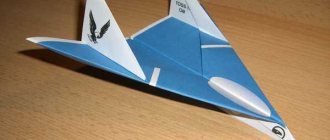
How to make a paper airplane so that it looks cool and still flies fast and far? At first glance, the task does not seem easy. But try running this model from a window into the jungle of the nearest park. Just keep in mind that you may not see him again. This plane will also fit perfectly in any pocket!
- Step 1: Take a regular piece of paper. All you need is paper, no tape, no scissors, no paper clips, just paper!
- Step 2: Start folding! You will need to make the most precise folds to get the best plane. First, fold the paper into a triangle and do the same with the other side. Now you need to fold the sides, fold the entire plane in half. Do not unfold it or fold the top so that the fold in the center completely overlaps the other. After this, fold both sides so that the corners touch each other, then unfold them. Fold the bottom piece so that it folds straight into the pleats on the sides. Now bend these sides so that they line up perfectly with the side of the plane.
- Step 3: Feathering. Now bend the wings along a line passing through the bottom of the plane.
- Step 4: Ready to fly. Next, hold the model closer to the center, bend the wings a little and throw it up a little with medium force and watch how it flies towards the horizon.
By following these step-by-step instructions, you will get a plane that will surprise you with its flight range.
Cash costs
How much does it cost to build a plane? Naturally, after setting the goal, deciding on the aircraft model, after selecting the location and allocating the time, the next question is precisely the financial part of the project.
It is impossible to give a definite answer to the question about the cost of the aircraft, since all models are different, which means the materials, quality and quantity are very different. We can only say that on average, from $50,000 to $65,000 (about 3-4 million rubles) is spent. However, the actual amount may be significantly higher or significantly lower. “Building an airplane” is a fairly simple phrase that requires a serious approach not only to the practical part, but also to the financial one. The easiest way would be to consider this action as repaying a loan. In other words, you need to estimate the total cost of the project in advance, break it down into parts, after which you can spend the planned amount of money every month on purchasing the necessary parts, tools, etc.
Another important factor is the understanding that you don’t have to install anything on the plane that you won’t need for the flight. The simplest example is flashlights for flying at night. If such walks are not planned, then there is no point in buying lighting. That is, correctly set goals will help you save a significant amount of money. You can save on installing instruments if they are not needed for the flight. The construction of aircraft requires the installation of a propeller. There are constant pitch and constant speed models. The first model costs about three times less than the second, but at the same time it is not so much inferior to the constant speed propeller in terms of flight efficiency.
Airplanes made from paper cylinders
Capture your child's imagination with this airplane made from recycled materials and scraps.
What you will need:
- 2 cardboard paper towel rolls
- a small piece of thick paper or foam
- glue
- scissors
- paint and brush
- stickers
The acquisition of knowledge
Building an airplane with your own hands is a labor-intensive and time-consuming task, but it is not at all as difficult as it seems at first glance. Many novice craftsmen who would like to try their hand at it think that they do not know how to paint, rivet and cook. In fact, learning all these skills is quite simple, it only takes a little time.
It is important to view the problem in this way. A home airplane, built with your own hands, is a mechanical device with a minimal set of electrical components, as well as a complete absence of complex hydraulic parts. All this can be studied and collected independently.
For example, what engine is on the plane? The most standard aircraft engine consists of the same structural parts as a motorcycle or boat engine. These are the simplest and most standard models that are perfect for building your first homemade aircraft. Next comes the practical part of the assembly. Riveting is a fairly simple process that can be mastered in just one day. As for working with a welding machine, everything is also simple here, you just have to spend more time on training so that the welding seams have good performance and are fairly even. As for any work with wood, it is used in everyday life quite often, and therefore the technique of processing it, as well as the tools for performing all the necessary operations, are not difficult to master and acquire.
Common patterns
One of the most common aircraft designs is a single-seat lightweight braced monoplane with a high wing and a pulling propeller. This model of a homemade aircraft first began to appear back in 1920. Since then, the layout, design, etc. have remained virtually unchanged. The finished sample today is considered one of the most tested, reliable and structurally proven. It is because of all these advantages, as well as because of the simplicity of the aircraft drawings, that it is an almost ideal option for DIY construction, especially for a novice craftsman. Over a long period of operation and assembly of such aircraft, they acquired characteristic features. They are distinguished by such design features as a wooden two-spar wing, a welded steel aircraft fuselage, fabric skin, a pyramidal chassis, and a closed cabin with a car door.
Further, it is worth noting that there is a small variation of this type of aircraft, which was used in the 1920-1930s. The type of aircraft was called a “parasol”. This model was a high-wing aircraft, which had a wing mounted on struts and struts above the fuselage of the aircraft. This type of high-wing aircraft is also found in current amateur aircraft construction. However, when compared with the usual standard model, the “parasol” is used much less frequently, since from a design point of view it is much more difficult to manufacture such a device, and in terms of its aerodynamic characteristics it is inferior to a standard aircraft. In addition, in terms of operation, they are also worse, and access to the cabin of such a unit is quite difficult, which leads to the difficulty of using the emergency method of leaving the cabin.
Simple airplane parts
It is worth considering some design features of these models.
An ordinary high-wing airplane with the name “Leningradets” has the following characteristics.
The engine for such a light single-seat aircraft has a power of 50 hp, and the model is called “Zündapp”. The wing area of the finished model should be equal to 9.43 m2. Take-off weight should not exceed 380 kg. This is very important, especially when choosing a pilot seat. The empty weight of the apparatus is usually approximately 260 kg. The maximum speed that the aircraft can reach is 150 km/h, and the rate of climb at the ground is 2.6 m/s. The maximum flight duration is 8 hours.
For comparison, it is worth considering “parasols”. In this case, an analysis of the model called “Baby” will be presented.
The engine is installed in the LK-2 model, the power of which is 30 hp, which already makes it less powerful than the standard model. The wing area is also reduced to 7.8 m2. The take-off weight of this aircraft is only 220 kg, which includes the pilot's seat and the pilot himself, the weight of the power plant, fuselage and other structural elements. Despite the fact that the take-off weight is significantly less than that of the Leningradets, the maximum speed is only 130 km/h.
Aircraft model making
Among the main advantages of such models, what stands out is that it is not difficult to control the aircraft, as experienced pilots do, since the controls themselves are quite simple. This is especially noticeable in cases where the specific load on the wing does not exceed 30-40 kg/m2. In addition, high-wing aircraft are distinguished by the fact that they have excellent takeoff and landing characteristics and are stable. In addition, the cabin is designed in such a way that it creates an optimal view of what is happening below. In other words, you simply cannot find a more optimal model for self-construction.
It is worth considering in more detail one of the most successful models - the high-wing aircraft, which was designed by V. Frolov.
The wing for such an aircraft was made of materials such as pine and plywood, the fuselage for the aircraft was made of steel pipes, which were connected by welding. All structural elements of the aircraft were made completely covered with fabric using classical technology in aircraft construction. The wheels for the chassis were chosen to be large enough. This was done so that it could take off from unpaved and unprepared sites without any problems. A 32-horsepower engine based on the MT-8 was used as the power unit, that is, the engine. It was equipped with elements such as a gearbox and a large-diameter propeller. The take-off weight of the aircraft with this design and engine was 270 kg, the flight balance was 30% of the MAC. With all these indicators, the specific load on the wing was 28 kg/m2. It was said earlier that it is much easier to fly an airplane like experienced pilots if the load does not exceed 30-40 kg/m2. The maximum speed of the aircraft was 130 km/h, and its landing speed was 50 km/h.
Aircraft model PMK-3
In the town of Zhukovsk near Moscow, the PMK-3 aircraft was created, which can now also be assembled independently. The aircraft differed from ordinary ones in that it had a unique structure of the nose of the fuselage, as well as a rather low landing gear. This aircraft model was designed according to the design of a strut-braced high-wing aircraft with a closed cabin. An entrance for the pilot was provided on the left side of the fuselage. In order to achieve the desired alignment, it was necessary to move the left wing a little back. This is very important to remember when assembling such a model with your own hands. The overall design of the aircraft is all wood, covered with canvas. Wing type: single-spar, with pine flanges.
The basis of the fuselage for this model was made up of three spars. Because of this design, the finished fuselage had a triangular cross-section. A 30 hp engine was chosen as the main power unit. The type of engine is an outboard motor of the “Whirlwind” type, which is liquid cooled. If the aircraft is properly designed, the radiator will protrude slightly from the starboard side of the fuselage.
It is worth saying a little about the fact that it is possible to build airplanes with a pusher type of propeller, but it is very important to remember that this will result in a loss of the thrust force of the device, as well as the lifting force of the wing. Because of these two features, it is important to consider the feasibility of installing such a propeller on a case-by-case basis, based on the builder's goal in creating the aircraft. However, it is fair to say that there were inventors who, while independently building an aircraft with such a propeller, creatively approaching the solution of this problem, were able to eliminate such shortcomings and operate the aircraft without them.
"KIT-set"
How to make an airplane easily? This question has recently become increasingly relevant. In general, it is worth noting that the increase in the number of people who want to build an aircraft with their own hands is ensured by the spread of “KIT kits”. This is a kit that includes all the necessary parts to assemble an aircraft of the selected model. In this case, you will still have to put your hands to assembly, but such a kit helps you skip the stage of selecting elements, adjusting to size, etc. With such kits, assembling an airplane turns into something like assembling a construction set.
Another advantage of a KIT kit is that it will be cheaper than assembling all the elements from scratch. Today there are three ways to acquire your own flying unit. The first is the purchase of a ready-made product, the second is a “KIT kit”, and the third is assembly from scratch. Purchasing a set in this case is an average price option. If we talk about complexity, then assembling an airplane from ready-made and fitted parts is much easier than from scratch yourself.
To sum it up, we can say the following. Firstly, building an airplane with your own hands nowadays is a completely realistic task, but it requires a lot of time and money. If you do not have welding and riveting skills, then you will also have to master them to successfully complete the job. To successfully assemble an aircraft, it is necessary to have drawings available, as well as an assembly diagram in which each stage will be clearly presented. If you don’t want to do all this, then you can purchase a “KIT kit”, which will simplify the task and reduce it to assembling a kind of construction set.
Made of plastic
Bottles are an affordable material that is always available in the house. You will need three more covers, one for the nose of the car and two for the chassis. Crafting an airplane from a bottle will delight a boy. This original product can be presented to grandfather or father for any occasion.
A plastic vessel is covered with newspaper using PVA glue. Cut out wings, tail and propeller from cardboard. All of them are covered with paper. They need to be dried well.
A plastic tube from a ball is suitable for the chassis. The lids are attached to it with a glue gun. Then the wings and tail are connected to the base. Afterwards the craft needs to be decorated and varnished.