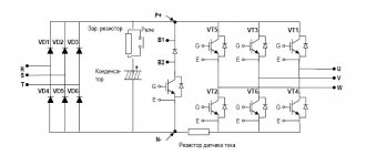
Stereo sound amplifier on TDA7262
Hi-Fi amplifier for two channels.
This microcircuit has a wide supply voltage range, and the output current reaches 3.5 amperes. A standby function and protection against short circuits and overheating during operation are also available.
Limit characteristics of the microcircuit
| Supply voltage Upit | 25 V |
| Output peak current | 4.5 A |
| Power dissipation Prass | 30 W |
| Working temperature Trab | -20…+85 °C |
Power supply for amplifier
The operation of the amplifier is very dependent on the power source. What the amplifier actually does is transfer energy from the power source to the speakers. But it does this under the control of a sound signal. The energy is transferred so that the signal in the speakers is exactly the same as at the amplifier input. How to make a correct and good power supply is described in the article Power supply for TDA7294.
How to properly make an amplifier and power supply to get maximum sound quality is written in these articles:
More information about amplifiers and sound enhancement:
Links given in the article
Amplifier based on TDA7293 / 7294 with T-shaped OOS
Power supply for TDA7294
Amplifier ground sharing
Connecting blocks inside the amplifier
Operation of an amplifier based on the TDA7293 (TDA7294) chip with a “difficult” load
Clip-detector for amplifier on TDA7293
Study of the upper limit of hearing
Information to better understand the operation of the amplifier and get maximum sound quality
Hi-Fi amplifier based on TDA7294 chip
Clipping in an amplifier
Amplifier power supply calculation
Transformer for powering the amplifier
The right straightener
Rectifier for an amplifier or the saga of a fast diode
Separate power supply for stereo amplifier channels
Capacitor array - myths and reality
Mute and StandBy modes in the TDA7294 / TDA7293 chip
Amplifier 50 W
A simple single-channel circuit based on TDA1514.
Chip characteristics
| Parameter | Meaning |
| Upit1 | +10…+30 V |
| Upit2 | -10…-30 V |
| Iout | 5 A |
| Irest | 56 mA |
| Pout | 50 W |
| Rin | 20 kOhm |
| Gain | 30 dB |
| Frequency band | 20-25,000 Hz |
| Harmonic distortion | 0,01 % |
| Rload | 8 ohm |
Pin assignment
| Pin number | Purpose |
| 1 | Non-inverting input |
| 2 | Protection circuit output |
| 3 | Supply Voltage Shutdown Circuit Output |
| 4 | Supply voltage (-27.5 V) |
| 5 | Exit |
| 6 | Supply voltage (+27.5 V) |
| 7 | Power amplifier feedback and correction input |
| 8 | Output shutdown circuit output |
| 9 | Inverting input |
Radio amplifier circuit, amplifier circuit for subwoofer and others
DIY 60W sound amplifier
DIY 60W sound amplifier
While there is some time, another brand new circuit appears on the site, we all know that the greater the power of the amplifier, the more expensive it is. But what can you do if you need an amplifier that is both powerful and at the same time not too expensive?
I would like to present to many a familiar circuit of a 25 or 60 watt permanent amplifier, the cost of which is pennies. As already mentioned, the power of the amplifier depends on the supply voltage and resistor values (60-watt values are indicated in parentheses).
TDA8567q 4x25 W
Hi-Fi class bridge amplifier for four channels.
There is protection against short circuit of the output stage and thermal protection with a reduction in output power when overheated. The microcircuit also has protection against voltage fluctuations and a shutdown mode. This microcircuit also has an on/off mode for the input signal (Mute mode), and protection against “clicking” when voltage is applied to the circuit.
Chip characteristics
| Parameter | Meaning |
| Upit | 6-18 V |
| Iout | 7.5 A |
| Irest | 230 mA |
| Pout | 4x25 W |
| Rin | 30 kOhm |
| Gain | 26 dB |
| Frequency band | 20-20000 Hz |
| Harmonic distortion | 0,05 % |
| Rload | 4 ohm |
Pin assignment
| Pin number | Purpose |
| 1 | Supply voltage |
| 2 | Exit 1+ |
| 3 | General |
| 4 | Output 1- |
| 5 | Output 2- |
| 6 | General |
| 7 | Exit 2+ |
| 8 | Supply voltage |
| 9 | Diagnostics |
| 10 | Input 1 |
| 11 | Entrance 2 |
| 12 | General signal |
| 13 | Entrance 3 |
| 14 | Entrance 4 |
| 15 | Mode selection |
| 16 | Supply voltage |
| 17 | Exit 3+ |
| 18 | General |
| 19 | Output 3- |
| 20 | Output 4- |
| 21 | General |
| 22 | Exit 4+ |
| 23 | Supply voltage |
↑ About the output power figures in the datasheet
Further.
You can't ask these (and other) amplifiers to do more than they can. Don't trust advertising promises too much. The power stated in the datasheet is usually exaggerated. That is, this is a deception, but formally everything is correct. It is written that such and such power is at 10% distortion or even with a meander. This is true, but it is impossible to listen with such distortion - your ears will wither. Honest power - with distortion no more than 1...2%, and for these amplifiers it is 25...30% lower than with distortion of 10%. You need to look at what load the amplifiers can operate with - 8 Ohms, 4 Ohms or even 2 Ohms. If an amplifier can drive a 2 ohm load, it can always drive a 4 ohm or 8 ohm load, but not vice versa.
I’ll get ahead and write that the TDA7266, TDA7297 microcircuits are capable of sounding stationary acoustics (there will be no disco), but this is not their profile. Their profile is bookshelf, computer, portable acoustics, including battery-powered ones.
Stereo amplifier 12 dB
The TDA8199 can be used with both electronic volume controls and simple potentiometers of the appropriate sound class.
Characteristics
| Supply voltage Upit | 10.8 - 13.2 V |
| Current consumption Ipotr | 21 - 28 mA |
| Gain output/input | 12 dB |
| Audio input impedance Rin | 22 - 1000 Ohm |
| Harmonic coefficient Kr | 0,35 — 1 % |
| Audio output impedance Rout | 30 - 1000 Ohm |
| Output noise voltage Uout noise | 30 µV |
Chip Limits
| Supply voltage Upit | 16 V |
| Working temperature Trab | -55…+125 °C |
| Storage temperature | 0…+70 °C |
ULF TDA8198 12 dB
The TDA8198 chip is manufactured in a DIP14 package and is used in high-end equipment.
The dynamic signal level is 90 dB.
There is protection of the output stage from short-circuit and static.
Chip characteristics
| Supply voltage Upit | 10.8 - 13.2 V |
| Current consumption Ipotr | 24 - 32 mA |
| Reference voltage Uref | 6.9 V |
| Output noise voltage Uout noise | 300 µV |
| Harmonic coefficient Kr | 0,3 — 1 % |
| Audio input impedance Rin | 22 kOhm |
| Audio output impedance Rout | 10 - 300 Ohm |
Chip Limits
| Supply voltage Upit | 16 V |
| Working temperature Trab | -55…+125 °C |
| Storage temperature | 0…+70 °C |
ULF TDA8196 12 dB
A simple power amplifier circuit using TDA8196. Scheme for a beginner radio amateur. Doesn't require many parts and is easy to assemble. Miniature bridge low frequency power amplifier with electronic volume control.
There is protection for the output stage against short circuits and thermal protection against overloads. And of course, protection against static. The amplifier can be adjusted either with a potentiometer or with a simple electronic volume control.
Specifications of TDA8196
| Supply voltage Upit | 10.8 - 13.2 V |
| Current consumption Ipotr | 12 mA |
| Reference voltage Uref | 6.6 V |
| Audio input impedance | 10 - 13 kOhm |
| Audio input impedance | 0.2 - 1 kOhm |
| Harmonic coefficient Kr | 0,4 — 1 % |
| Output noise voltage | 40 µV |
Chip Limits
| Supply voltage Upit | 16 V |
| Working temperature Trab | -55…+125 °C |
| Storage temperature | 0…+70 °C |
Connecting the volume control
If there is no preamplifier, then the volume control is connected directly to the amplifier. It is important that the input circuits do not have contact with ground or the amplifier housing.
It is recommended to use a variable resistor (potentiometer) with a resistance of 30...50 kOhm as a regulator. The maximum resistance values of the volume control are 5...100 kOhm, but a slight deterioration in sound quality is possible.
It is better to use a variable resistor with an exponential dependence of the resistance on the angle of rotation. Then, when you rotate the control knob, the volume will change in proportion to the angle of rotation. Such Russian-made variable resistors are designated by the letter B, and resistors not produced in Russia are designated by the letter A.
TDA7265 and two inclusion options
There are two options for turning on the microcircuit.
- Large power range (+-25V);
- Bipolar power supply circuit;
- Power 2x25 W
- There is a silent mode and a standby function;
- Thermal protection against overheating during amplifier operation;
- There is short-circuit protection.
Bridge version of the amplifier on TDA7265
Chip characteristics
| Supply voltage Upit | 25 V |
| Output voltage in idle mode | 80 - 130 mV |
| Current consumption in idle mode Ipotr | 65 - 120 mA |
| Bias current at the non-inverting input Ibias | 500 nA |
| Output power Pout | 20 - 25 W |
| Harmonic coefficient Kr | 0,01 — 0,7 % |
| Gain (Open Loop) | 80 dB |
| Input resistance Rin | 15 - 20 kOhm |
| Shutdown temperature | 145 °C |
Limit parameters of the microcircuit
| Supply voltage Upit | 25 V |
| Output peak current | 4.5 A |
| Power dissipation Prass | 30 W |
| Operating temperature Trab | -20…+85 °C |
| Storage temperature Tstore | -40…+150 °C |
Parts used
The amplifier is easy to assemble even for beginners and is insensitive to the quality of components. But to obtain the best parameters and the best possible sound, the amplifier must be assembled from high-quality parts. High quality doesn't have to be expensive.
It is better not to use components from an unknown manufacturer: they may have poor parameters. When using such components, the amplifier may work poorly or not work at all.
The list of used parts (BOM List) can be downloaded from the following links:
In Russian:
hi-fi-7294-2020-bom-rus
In English:
hi-fi-7294-2020-bom-eng
Resistors
The amplifier uses inexpensive metal film resistors. All resistors except R9 with a power of 0.125...0.25 W. If the R9 is made in Russia, then a power of 0.5 W is sufficient. If the R9 is not made in Russia, then it is recommended to install an R9 with a power of 1 W. It is more reliable for operation at maximum power or as an instrumentation amplifier.
If you are planning a stereo amplifier or a multi-channel amplifier, then it is advisable to use resistors included in the negative feedback circuit (R2...R5) with an accuracy of 1% or better (more accurate than 0.25% are not needed). In this case, the imbalance in the volume of stereo channels will be minimal. If only resistors with an accuracy of 5% are available, then they should, if possible, be selected with the same resistance in all channels. Other resistors are not critical to the accuracy value.
Resistor R10 is of great importance. This resistor serves to separate the ground in the amplifier. But the input and output lands must not only be separated, but also necessarily connected. If resistor R10 is missing, has poor contact or too much resistance, then the amplifier will not work. Therefore, it is important that this resistor is reliable and of high quality and has the required resistance. This resistor does not need audio quality.
In principle, resistor R10 can be replaced with a jumper.
Ceramic capacitors
Ceramic capacitors C1 and Cx are made from high-quality low-voltage ceramics, with a maximum operating voltage of 50 volts. High-quality ceramics are determined by the temperature coefficient of capacitance (TCC). These capacitors must be TKE class NP0 (NP0), or C0G. Sometimes instead of the number 0 they write the letter O (NGO, NPO) - it’s the same thing. The manufacturer of the capacitors is important. It is better not to use noname capacitors. For example, Murata, Vishay, EPCOS are suitable. You can use Russian-made capacitors.
Selecting the capacitance of capacitors C1 and Cx
Capacitor C1 cuts the high frequencies entering the amplifier input (it forms a low-pass filter), and thereby suppresses high-frequency interference. However, this narrows the operating frequency range of the amplifier in the high frequency region. The capacitance of capacitor C1 is selected based on the resistance value of the volume control and the required cutoff frequency of the low-pass filter (LPF), which forms this capacitor together with resistor R1 and the resistance of the volume control. I offer a choice of one of two frequencies: 50 kHz and 70 kHz.
The cutoff frequency of 50 kHz is selected to provide stronger suppression of possible high-frequency noise coming into the input.
The sources of such interference can be both communication equipment (mobile devices, Wi-Fi and Bluetooth, radio communications, television), and other industrial and household devices.
But high-frequency interference arises not only from interference from radio communication systems. Ultrasound may be coming to the amplifier input from the CD player (more precisely, its DAC) - the sampling frequency is not sufficiently filtered. Or, for example, from a vinyl record player - where ultrasound is generated when the pickup stylus moves along the groove of the record.
If you are sure that there is no high-frequency interference, then the cutoff frequency of the input filter can be set to 70 kHz. In this case, the amplifier can have a maximum operating frequency of approximately 50 kHz.
By selecting an input filter cutoff frequency of 50 kHz, the amplifier can have a maximum operating frequency of approximately 40 kHz.
The capacitance values of capacitor C1 depending on the resistance value of the volume control and the required cutoff frequency of the input filter.
| Volume control resistance, kOhm | Capacitance of capacitor C1 required to obtain the cutoff frequency of the input filter 50 kHz, pF | Capacitance of capacitor C1 required to obtain the cutoff frequency of the input filter 70 kHz, pF |
| There is no volume control at the amplifier input: a preamplifier is used or the volume is controlled by the computer sound card | 2200 | 1500 |
| 5 | 1200 | 820 |
| 10 | 820 | 560 |
| 20 | 510 | 360 |
| 30 | 360 | 240 |
| 50 | 220 | 160 |
| 100 | 120 | 82 |
Capacitor Cx performs several functions simultaneously:
- — improves the stability of the amplifier;
- — increases the depth of negative feedback (NFB) at high frequencies and reduces distortion;
- — at high frequencies it boosts the signal in the OOS circuit, which virtually eliminates the possibility of dynamic distortion.
Capacitor Cx, like C1, reduces the upper cutoff frequency of the amplifier.
Both capacitors operate at frequencies above 20 kHz, so they have virtually no effect on the reproduction of high audio frequencies. The combined use of these capacitors results in no dynamic distortion occurring in the amplifier at all. However, some people want an amplifier with a frequency range of up to 40...50 kHz. This is their right, despite the fact that most people cannot hear signals above 20 kHz (a small study on this topic was published in the article Studying the Upper Limit of Hearing). In addition, the influence of any filters on the frequency response occurs smoothly, so even if the upper limit frequency of the amplifier is 50 kHz, at a frequency of 20 kHz the amplitude-frequency response (AFC) of the amplifier has a block, albeit microscopic.
Selecting the capacitance value of the capacitor Cx.
Option 1. The cutoff frequency of the input low-pass filter is 70 kHz.
| Capacitor capacity Cx, pF | Upper limit frequency of the amplifier at the level of -3 dB, kHz | Amplifier frequency response at 20 kHz, dB |
| 47 | 54 | 0,5 |
| 56 | 50 | 0,6 |
| 68 | 46 | 0,65 |
| 75 | 44 | 0,7 |
| 82 | 42 | 0,8 |
Option 2. The cutoff frequency of the input low-pass filter is 50 kHz.
| Capacitor capacity Cx, pF | Upper limit frequency of the amplifier at the level of -3 dB, kHz | Amplifier frequency response at 20 kHz, dB |
| 47 | 42 | 0,8 |
| 56 | 40 | 0,9 |
| 68 | 37 | 1 |
A frequency response rolloff at a frequency of 20 kHz of 0.8 dB, and even more so 1 dB may seem too large. But in reality it is invisible:
- it is below the hearing sensitivity threshold at this frequency,
- at a frequency of 20 kHz there is practically no sound,
- not all people hear this frequency
In fact, the capacitance of these capacitors may differ slightly from the specified value. A change in the capacitance of the frequency-setting capacitors by 10...20% will not be noticeable. But if you change the capacitance of these capacitors, then it is still better to expand the frequency response: increase C1, and decrease C2 and Cx.
Film capacitors
Capacitors C2, C4, C6, C7, C9 are lavsan film (other names for dielectric are mylar, polyester, MKT).
The most important capacitor for sound is C2. It must be of good quality. In this place, you can use a capacitor with a polypropylene dielectric (MKP). You most likely won't notice any difference in sound, but you'll still be pleased that you did your best to get high quality sound.
In fact, to get good sound, it is much more important to use the correct power supply and the correct installation of the amplifier blocks inside the case. But in any case, capacitor C2 should not be bad.
Capacitor C6 has the least effect on sound quality. In principle, it can even be excluded from the scheme. However, even in this place it is not recommended to use a bad capacitor.
Capacitor C4 improves the stability of the amplifier. Its maximum operating voltage can be up to 250 volts. If there is a choice, then it is recommended to choose the largest size of all available capacitors, but such that it can be normally installed on the board. When the amplifier is operating, a relatively large high-frequency current passes through this capacitor, and the capacitor can heat up. The larger the capacitor, the less heat it generates. Be reasonable! The capacitor size of 7.5 mm is quite sufficient!
Capacitors C7 and C9 help capacitors C8 and C10 supply power to the amplifier at high frequencies. The capacity of these capacitors is 2.2...4.7 μF, the maximum operating voltage is at least 63 volts. Capacitors must be of high quality to work well. The larger the capacity the better, but be smart. It is important that the length of the leads of these capacitors is minimal - the inductance of long leads will interfere with their operation. Therefore, a smaller capacitor with short leads will perform better than a larger capacitor with long leads.
"Green" capacitors can be used in positions C4 and C6.
Good capacitors don't have to be expensive. Moreover, it is better to use “regular” capacitors from a well-known manufacturer than capacitors from an unknown one.
Selecting the capacitance of capacitor C2
The capacitance value of capacitor C2 determines both the lower limiting frequency of the amplifier and the roll-off of the amplifier’s frequency response at low frequencies. This capacitor, together with the input impedance of the amplifier, forms a high-pass filter (HPF), passing frequencies above 10...25 Hz and suppressing frequencies below this value.
What the amplitude-frequency response looks like in the low-frequency region at different values of the capacitance of capacitor C2 is shown in the figure (high frequencies in this figure are shown conventionally).
Frequency response of the amplifier at different values of C2.
Amplifier parameters depending on the capacitance of capacitor C2.
| Capacitance of capacitor C2, µF | Lower limit frequency of the amplifier at the level of -3 dB, Hz | Amplifier frequency response at 20 Hz, dB | Amplifier frequency response at 25 Hz, dB | Amplifier frequency response at 30 Hz, dB |
| 0,22 | 22 | 3,3 | 2,5 | 1,8 |
| 0,33 | 14 | 1,8 | 1,3 | 0,9 |
| 0,47 | 10 | 0,9 | 0,6 | 0,5 |
| 0,68 | 7 | 0,5 | 0,3 | 0,2 |
| 1,0 | 5 | 0,2 | 0,2 | 0,1 |
| 1,5 | 3 | 0,1 | 0,1 | 0,05 |
Strategy for choosing the capacitance value of capacitor C2
The larger the capacitance C2, the lower the lower cutoff frequency of the amplifier (that is, the amplifier amplifies lower frequencies quite strongly), and the smaller the frequency response rolloff at low audio frequencies.
But to say that the larger the C2 capacity, the better the low frequencies are reproduced, it will be incorrect.
Indeed, if the frequency response of your speakers starts at 40 Hz, then everything that happens below 30 Hz should not bother you.
It would be more correct to say this: if the capacitance of capacitor C2 is less than a certain value, then the volume of the lowest frequencies in the audio range will decrease. For example, if C2 = 0.68 μF, then the frequency response rolloff at a frequency of 20 Hz is 0.5 dB - this is much less than the hearing sensitivity limit at this frequency, so we probably won’t hear such a rollover. In this case, the amplifier reproduces frequencies starting from 7 hertz. If the capacitance of capacitor C2 is reduced to 0.1 μF, then the volume at the very, very low frequencies will decrease slightly. We will notice this only with a very good soundtrack and excellent speakers. And then only during comparative listening. But let's notice!
Are such low frequencies necessary?
They say that if the amplifier reproduces absolutely all low frequencies, starting with constant voltage, then this improves the sound. They even talk about the constant component of sound. These are all advertising and marketing gimmicks that have nothing to do with reality.
The constant component of sound is atmospheric pressure, and no speaker can change it. And infrasound frequencies, which can reach the amplifier output and be reproduced by speakers, are harmful to humans. For example, infrasound frequencies that coincide with the frequency of the alpha rhythm of the brain (frequencies 7 ... 15 Hz) can cause headaches, disorientation and even panic.
A large number of infrasound frequencies are generated when playing vinyl records. Especially old ones: warped and eccentric. But even when playing new gramophone records, infrasound still occurs: it is created both by the player’s engine (rumble) and by the physical processes of friction of the stylus in the groove. Douglas Self wrote about this in detail in his book Electronics for Vinyl.
Fortunately, most speakers at these frequencies cannot create significant sound pressure, but it is better if these frequencies are cut off in the amplifier.
Another reason for refusing to reproduce very low frequencies is the physical processes in the loudspeakers. For equal volume as the frequency decreases, the diffuser stroke increases in proportion to the second power. That is, if the frequency is halved, the diffuser stroke should increase 4 times. In fact, the cone stroke increases even more due to a decrease in hearing sensitivity at the lowest frequencies. But the linear range of the loudspeaker is limited, so significant low frequencies can overload the loudspeaker, and the entire sound will be distorted.
Speakers with a bass reflex (PI) are especially susceptible to this phenomenon - at frequencies below the PI tuning frequency, the diffuser stroke is not limited in any way. In this case, the speaker practically does not emit sound, since an acoustic short circuit occurs: the sound emitted by the loudspeaker and the sound emitted by the bass reflex are subtracted from each other almost to zero.
The result is that there is no audible overload and the sound is poor. So from this point of view, limiting the reproduction of very low frequencies has a positive effect on the operation of the entire system, on sound quality and on human perception of sound.
On the other hand, the higher the cutoff frequency of the amplifier, the worse the transient processes when reproducing a low-frequency musical signal (not indefinitely, but up to certain limits). The bass, especially in bass reflex speakers, tends to be a little tighter.
So from this point of view, it is also undesirable to greatly increase the lower cutoff frequency of the amplifier.
What to do?
The output is this: the cutoff frequency of the high-pass filter formed by capacitor C2 should be 2...3 times less than the lower operating frequency of the speakers connected to this amplifier. But not lower than 10 Hz. And don’t be afraid of blocking the frequency response at low frequencies! A rollover of 1 dB at frequencies below 30 Hz is not noticeable by ear.
Personally, I most often use capacitor C2 with a capacity of 0.33 μF, and less often with a capacity of 0.47 μF.
To select the capacitance of capacitor C2, use this table.
| Amplifier purpose | Capacitance of capacitor C2, µF |
| Speakers of average quality with a lower operating frequency of 50...80 Hz. Especially recommended for vinyl playback | 0,22 |
| Higher quality speakers with a lower operating frequency of 30...40 Hz High quality speakers with powerful bass and a lower operating frequency of 20...30 Hz when playing vinyl | 0,33 |
| High-quality speakers with powerful bass and a lower operating frequency of 20…30 Hz. Quality subwoofer for vinyl playback | 0,47 |
| Quality subwoofer when playing vinyl Quality subwoofer | 0,68 |
| High quality subwoofer | 1,0 |
| Subwoofer for maniacs | 1,5 |
For myself and to order (in agreement with customers after studying their requirements and their equipment), I usually make two versions of the amplifier (a pre-amplifier with a volume control is used):
- “Standard” with the following set of element values: C1 = 2200 pF (input filter cutoff frequency 50 kHz), Cx = 47 pF, C2 = 0.33 µF polypropylene (MKP) Epcos or K78-19.
- "With extended frequency range." With this set of element values: C1 = 1500 pF (input filter cutoff frequency 70 kHz), Cx = 47 pF, C2 = 0.47 µF polypropylene (MKP) Epcos or K78-19.
The amplitude-frequency characteristics of these two amplifier options are shown in the figure.
Electrolytic capacitors
Positions C3 and C5 should contain regular high-quality capacitors. Capacitor C3 sets the turn-on time of the amplifier and does not affect the sound. But if it is of poor quality or has a large leak, then the amplifier may not turn on. With a poor-quality capacitor C5, the maximum undistorted output power is much less than it could be.
Capacitors C8 and C10 perform three functions at once:
- Additionally, supply voltage ripple is suppressed.
- They feed the amplifier at peak volumes. Capacitors C8 and C10 are installed very close to the chip, and the conductors coming from these capacitors are very short. Therefore, these conductors have very low resistance and inductance. As a result, if necessary, all the energy from these capacitors quickly enters the microcircuit and is transmitted to the output of the loudspeakers.
- They pass loudspeaker current through themselves at medium and high frequencies. As a result, this current is closed through the shortest path.
All these functions are actually combined. Physically this is one function. I separate them mentally to make it easier to analyze them.
The functions of capacitors C8 and C10 are very important, so these capacitors must be of good quality. It is very useful to use Low ESR or Low Impedance capacitors in this position.
However, be reasonable! The importance of the quality of capacitors C8 and C10 is often exaggerated. There is no point in using exotic “magic” supercapacitors. Good capacitors from a reliable manufacturer are quite enough. It is important that these capacitors are properly soldered to the board. Moreover, they have leads of minimal length, which means minimal resistance and inductance.
It is not recommended to use capacitors C8 and C10 with a capacity of less than 1000 µF. It is also not recommended to significantly increase their capacity. You can use capacitors with a capacity of 2200 µF, but with a high-quality power source there will be no difference.
At high frequencies, electrolytic capacitors C8 and C10 are assisted by film capacitors C7 and C9, so these capacitors must also be of good quality.
Bridge to TDA7240
A miniature but quite powerful low-frequency power amplifier, made using a bridge circuit.
The amplifier has:
- Protection of the output stage from short circuit;
- Thermal protection in case of overload;
- Reliable protection against surges up to 28 V.
Chip characteristics
| Upit | 6 - 18 V |
| Iout max | 4.5 A |
| Irest | 150 mA |
| Pout | 20 W |
| Rin | 50 kOhm |
| Gain | 40 dB |
| Frequency band | 30 - 25 kHz |
| Harmonic distortion | 0,5 % |
| Rload | 4 ohm |
Pin assignment
| Pin number | Purpose |
| 1 | Distortion Compensation Circuit Output |
| 2 | Output of correction scheme |
| 3 | Entrance |
| 4 | General |
| 5 | Output 1 |
| 6 | Supply voltage |
| 7 | Exit 2 |
ULF circuit on TDA7236
The microcircuit is in a minidip (4+4) package.
Chip characteristics
| Supply voltage Upit | 1.8 - 24 V |
| Current consumption with idle mode Ipotr | 5 mA |
| Output power Pout | 1.7 W |
| Harmonic coefficient Kr | 0,3 — 1 % |
| Gain (closed loop) | 38 dB |
| Input resistance Rin | 100 kOhm |
Limit parameters
| Supply voltage Upit | 28 V |
| Output current Iout | 1 A |
| Power dissipation Pdis | 500 mW (SZIP package), 800 mW (SSOP package) |
| Temperature Tb | 40…+150 °C |
Block diagram of the TDA1557Q chip
Dimensions TDA1557Q
Typical connection diagram TDA1557Q
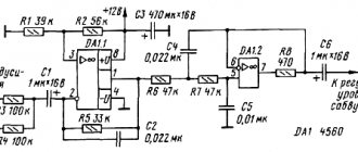
Schematic diagram of switching on TDA1557 with switch-on delay
A delay chain of 100kOhm, 1kOhm resistors and a 100.0x16V capacitor turn on the amplifier with a delay to eliminate clicks in speaker systems.
Typical wiring diagram TDA1557
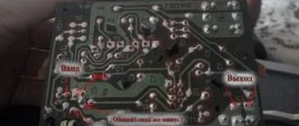
Amplifier PCB
DIY simple amplifier based on TDA1558Q
Amplifier based on TDA7052
Used in portable audio equipment
An amplifier assembled according to this scheme has a number of advantages:
- No external elements needed;
- Minimal interference when turning on and off;
- Sufficiently high stability of operation when amplified;
- Low power consumption;
- No need for an additional radiator
- There is short-circuit protection.
Chip characteristics
| Supply voltage Upit | 3 - 18 V |
| Current consumption in idle mode Ipotr | 4 - 8 mA |
| Gain factor Kusil | 38 - 40 dB |
| output power | 1.2 W |
| Harmonic coefficient Kr | 0,2 — 1 % |
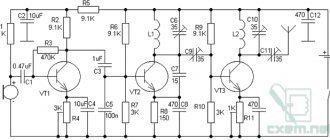
A pair of amplifiers on the TDA7050 chip
The supply voltage is only 1.6 V and this circuit is excellent for operation on batteries and rechargeable batteries.
The circuits are simple enough to be assembled by novice radio amateurs. It can also be assembled on a breadboard.
Bridge version of the microcircuit amplifier
Advantages of the microcircuit:
- A small number of external elements necessary for the operation of the microcircuit;
- Low current consumption;
- Gain 26 dB;
- Floating differential input;
- The chip has stereo and bridge modes.
Chip characteristics
| Supply voltage (Upit) | 1.6 - 6 V |
| Current consumption in idle mode (I consumption) | 3.2 mA |
| Output power in bridge mode | 140 mW |
| Output power in stereo mode | 75 mW |
| Channel Separation | 40 dB |
Source of schematics
S. R. Bashirov, A. S. Bashirov Modern integrated amplifiers
Installing the TDA7294 chip
Depending on the chip used, a jumper is installed on the board in the desired position.
Installing the TDA7294 or TDA7293 jumper
If the jumper is set to TDA7293, the empty square pad labeled TDA7294 can be filled with solder.
Filling the pad
It will be very, very little, but better.
The chip must be installed on a radiator with an area of at least 700 square centimeters. When installing the microcircuit on a radiator, you must use thermal paste. The radiator must be freely cooled by air.
Important! The housing of the microcircuit is connected to the minus of the power supply, therefore, in order to avoid a short circuit of the power source, you must either install the microcircuit through an insulating gasket (and isolate the screw that secures the microcircuit to the radiator), or reliably isolate the radiator from the housing.
In the first version, the microcircuit is cooled a little worse. In the second, it is possible to accidentally short-circuit an energized radiator to the housing.
Do what is most convenient for you.
Several microcircuits can be installed on one radiator, and the area of the radiator can be increased by as many times as the number of microcircuits installed on it. But the power wires must be suitable for each of the amplifier boards . You cannot “pass power” from one microcircuit to another through a radiator! The fact that the microcircuit's flange is connected to the power supply negative does not mean that the microcircuit can receive power through its flange!
You can attach the board to the radiator simply by screwing the chip to it. This method is applicable if the board does not use heavy exotic components and if there is no vibration during operation of the amplifier. An example of such board mounting in the amplifier case is shown on the Four-channel amplifier page.
The board dimensions and connection dimensions are shown in the figure. The flange of the microcircuit protrudes beyond the dimensions of the board by 1...2 millimeters, depending on how the microcircuit is oriented during soldering.
For more reliable fastening, you can use a special mounting hole for a screw with an M3 thread. This hole is isolated from the circuit.
The principle of using this hole is quite simple, the main thing is that nothing closes.
Mounting idea