Many electrical devices can be reused after they break down. Most of them can become valuable material, a kind of recyclable material for recycling. You can find various instructions on the Internet for unusual homemade products based on the devices you are interested in. So, craftsmen quickly realized that they could make a power supply unit (PSU) from a failed energy-saving lamp (ESL) with their own hands.
Circuits for energy-saving lamps can be called a half-finished power supply. All that remains is to make an isolation transformer, then a rectifier and remove unnecessary parts. Also remember that to develop a power supply, you should choose an ESL with a power of at least 20 W; other lamps can be used for spare parts.
The output voltage of such a unit will be constant, but alternating voltage is not provided in energy-saving lamps. In practice, it happens that lamps from other manufacturers have different circuits, but the difference is usually not very strong.
Energy saving light bulb ballast source
According to the characteristics of energy-saving lamps, the base of each of them contains a so-called electronic ballast - a miniature circuit that prevents the lamp from flickering when turned on and ensures gradual heating of the cathode coils. Thanks to it, the gas in the flask emits a glow with a frequency of 30 to 100 kHz.
CFL disassembled
Inside view of a fluorescent light bulb
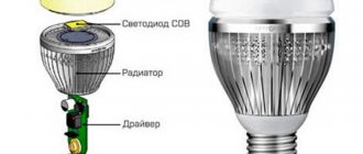
The design of an energy-saving lamp using the example of a product from Camelon
Operating at such high frequencies significantly increases the energy consumption coefficient, bringing it to almost unity, which explains the high efficiency of fluorescent lamps of this type. Additional advantages of high-frequency electricity are the absence of noise and electromagnetic fields perceived by the human ear.
Depending on how the electronic choke for fluorescent lamps is designed, it can light up immediately at full intensity, or reach maximum brightness gradually. Sometimes this takes one or two minutes, which, of course, is not very convenient. Manufacturers do not indicate the heating time for the lamp, and the buyer has the opportunity to check it only after starting to use the product.
The overwhelming majority of ballast circuits, which are essentially voltage converters, are assembled using semiconductor transistors. Expensive lamps use a more complex circuit, while cheap lamps use a simplified circuit.
Here's what you can profit from if you have a usable or burnt-out fluorescent lamp on hand:
- bipolar transistors designed for voltages up to 700 V and currents up to 4 A, often already with protective diodes (D4126L or similar);
- field-effect transistors (quite rare);
- pulse transformer;
- throttle;
- bidirectional dinistor, similar to the dual dinistor KN102;
- 10/50V capacitor.
When assembling a homemade power supply, some types of electronic ballast for energy-saving lamps are not just a source of components, but represent a significant part of the circuit, which can only be slightly supplemented and changed.
Converters containing electrolytic capacitors are considered not very successful. It is these elements that especially often cause breakdowns in electronic devices.
Lamp repair.
If at least one of the spirals burns out, throw away the flask; if not, then it is working, and the circuit does not work.
In some cases, it is possible to restore the functionality of a lamp with a burnt-out spiral by short-circuiting it. Alternatively, close it with a high-power 8-10 Ohm resistor and remove the diode that shunts this spiral, if any. If a fuse blows (sometimes it comes in the form of a resistor), which usually happens when capacitor C3 breaks down, transistors Q1, Q2 are probably faulty; as a rule, transistors MJE13003 and resistors R1, R2, R3, R5 are used. Instead of a blown fuse, you can install a resistor of several ohms.
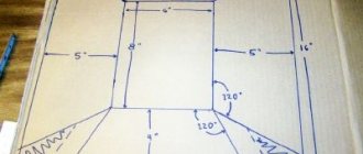
Before assembly, it is necessary to drill ventilation holes in the lamp base to make the operating temperature more mild. A series of holes around the mounting location of the lamp tube serves to remove heat from the tube itself. A series of holes closer to the metal part of the base serves to remove heat from the ballast components. You can also make another row of holes - in the middle, of a larger diameter.
This modernization of an energy-saving lamp will help to significantly extend its service life. You should not install the upgraded lamp in places with high humidity (for example, a bathroom).
The most favorable conditions for the operation of energy-saving light bulbs are in an open form, or in a wide lampshade or a lampshade with ventilation, with the base up.
Benefits of replacing fluorescent light bulbs with LEDs
Switching to identical LED sources will allow you to achieve energy savings of 2-3 times. Moreover, this is true for any light bulb, regardless of its form factor. Do not forget that modern technologies are constantly improving, and in the case of LED, humanity has not yet reached its maximum heights of development. In the future, such products will be even more effective.
To feel the significant benefits when switching from fluorescent lamps to LEDs, let’s calculate the difference in power for an apartment. Let's say 10 lamps are used, and the average operating time of each is 3 hours per day. Multiply these values with 30 days and get 90 hours per month. Let each lamp consume 50 W/h, which means the monthly consumption is 45 kW. If the cost of 1 kW is 10 rubles, then the payment for electricity when using one such lamp will be 450 rubles.
When switching to LEDs and wanting to keep room illumination at the same level, it is enough to take 20 W LED sources. Thus, 18 kW will be consumed per month for lighting, and the payment for electricity will be 180 rubles. This is 2.5 times less, but in reality this figure can be much higher.
Distinctive qualities
A pulse soldering iron has some differences from traditional devices used for soldering:
operation in pulse mode, only when the button is pressed;- quick warming up to operating temperature, the time of which does not exceed a few seconds;
- The tip of a pulse soldering iron is a conductor heated by the current flowing through it.
A conventional electric soldering iron is a device with significant inertia. Its tip is made of copper rod. Heating is carried out by contact method, by heat transfer from a nichrome spiral heated by electric current.
Heating of such a device can last several minutes, which naturally causes inconvenience. For this reason, such soldering irons are not turned off.
Pulse soldering irons are made in the form of pistols with a power button located in the trigger area. At the end of the “barrel” there is a loop of copper wire, which plays the role of a pulse soldering iron tip.
For the convenience of soldering, a backlight is usually located near the tip, which turns on when the power button is pressed. The role of backlight in older models of pulsed soldering irons was played by a low-voltage incandescent light bulb; modern models use LEDs.
How to connect a UPS to a screwdriver
The power tool must be disassembled by unscrewing all screws.
Typically, the screwdriver body consists of two halves. Next, you should find the wires that connect the engine to the battery. These wires can be connected to the UPS output using soldering or heat-shrink tubing; twisted wires are not recommended.
To enter the wire from the power supply, a hole must be made in the tool body
It is important to take measures to prevent the wire from being pulled out in the event of careless movements or accidental jerks. The simplest option is to crimp the wire inside the housing near the hole with a clip made from a short piece of soft wire folded in half (aluminum will do)
Having dimensions exceeding the diameter of the hole, the clip will not allow the wire to come off and fall out of the housing in the event of a jerk.
Energy-saving lamps are gaining more and more popularity, allowing you to save energy; they also have an even white light; there are also warm light lamps, similar in color to incandescent lamps. But unfortunately, energy-saving lamps also do not last forever, some people simply throw them away, while others... make useful homemade products out of them.
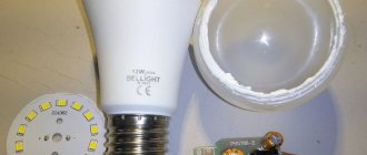
In this article we will look at how to make a simple switching power supply from an energy-saving lamp. In most cases, in an energy-saving lamp, the filaments located in the bulb fail, but the electronic part remains intact.
We take a faulty energy-saving lamp. And using a screwdriver we pry off the two halves of the body. We follow the contour and alternately bend one half from the other.
Approximately all energy-saving lamps are made according to this scheme:
In order to make a switching power supply, we will change it to this form:
First, we remove all the pins, two capacitors and diodes (if any), as you can see in the photo, I didn’t have them.
We remove the pulse inductor, there are two options, the first is that the secondary winding is wound into the free space of the inductor and it is installed back on the board. In this case, it will not be possible to obtain more power. The second method is to wind a pulse transformer, for example, on a ferrite ring. When installing radiators on transistors, you can get a power of 100W or more.
I didn’t need a lot of power, the goal was to power a meter of white LED strip to make something like a kitchen night light :). I also chose about 8-10 Volts for the supply voltage, so that the tape would not glow very brightly; in this mode of operation it would last much longer.
Popular articles Ladybug pot holder
The throttle is removed, we disassemble it, this is quite easy to do, unwind the yellow synthetic film, and take out the two halves of the ferrite. Before winding the secondary winding, you need to make insulation, simply wrap electrical cardboard, plain paper, or plumbing tape around the primary winding. Next we wind a few turns.
We also make insulation and bring out the edges of the winding.
We assemble the transformer in the reverse order; I used “Second” type glue.
We install the transformer on the board. We connect P1 and P4 with a jumper (see the diagram).
For testing, I connected the rest of the coil of LED strip, having first rectified the voltage using a diode and a capacitor. The output voltage was 9 Volts.
The switching power supply from the energy-saving lamp is ready, working, nothing gets hot on the board.
Is it possible to increase the power
The power of a power supply made from electronic ballasts usually does not exceed 40 W, which may not be enough. In addition, the inductor installed in the circuit introduces additional restrictions. The system simply cannot reach maximum power and even 40 W is rarely seen. Increasing the current does not produce the desired effect, since the magnetic circuit begins to function in saturation mode, reducing the efficiency of the circuit.
Appearance of a pulse transformer
To increase the power of the power supply, it is enough to connect a pulse transformer instead of a standard inductor. The process is more complicated than remaking an energy-saving lamp, but you can still do it yourself if you have knowledge in the field of radio engineering.
The transformer can be removed from a computer power supply or other equipment. Additionally, a 5-ohm resistor with a power of 3 W and a high-voltage capacitor with a capacity of about 100 μF with an operating voltage of 350 V are required.
The connection diagram is shown below.
Power supply circuit from electronic ballasts with a pulse transformer to increase power
The pulse transformer is installed in place of the inductor. The primary winding is connected to the converter, the secondary is a step-down winding. Increasing the resistor power and capacitor capacity completes the change to the standard electronic ballast-based power supply circuit.
Now it is possible to deliver a current of 8 A at a voltage of 12 V. This means that the power supply can be used in screwdrivers or household appliances with similar requirements.
How to make an LED lamp
Necessary materials
In order to convert an energy-saving light bulb into an LED light bulb with your own hands, you need to have the following list of materials with you:
- A burnt out, broken lamp.
- A small piece of fiberglass for connecting parts together. If you have other ideas (besides soldering), you can use yours to solve the question of how to attach the LEDs.
- A set of radio elements corresponding to a specific circuit, including LEDs. Experts advise choosing ordinary parts for assembling an LED light bulb with your own hands, which are presented in a large assortment on every radio market, where their cost is significantly lower.
- A capacitor with a volume of 0.022 Mf, the voltage in which is 400 V, one resistance is designed for 1 mOhm and a pair of resistances for 200 Ohms.
- LEDs are cheaper to solder in the required quantity using a strip.
Making a circuit
The process of creating a circuit with your own hands begins with cutting out a circle with a diameter of 30 mm from PCB. Next, apply paths on the circle; nail polish does a good job of this. After covering one coat, set the piece aside until it is completely dry.
Element connection diagram
At this time, you can do chemistry, namely, make a mass with your own hands that dissolves copper. To do this, mix copper sulfate and ordinary kitchen salt in a ratio of 1:2. Be sure to add a small amount of warm water (but not hot!) and dip the future board into the resulting mixture. Within a day, you will notice how the copper has disappeared from the textolite circle, only the part that was treated with varnish remains.
At the final stage, soldering is performed. However, before moving on to this phase, use a special solvent and get rid of the varnish layer. Then tread the existing paths.
LED lamp circuit
Take a millimeter drill and make holes in the areas where the elements are fixed. Finally, move on to full soldering of the circuit. If you are not new to working with a soldering iron and have certain skills, to create a 220 V LED light bulb with your own hands, or rather, its driver board, you just need to set aside 30 free minutes.
The assembly process is not complete without disassembling the old energy-saving lamp. Use a metal saw to cut the perimeter at the very end of the plastic. Take out all the internal parts, leaving only the wires coming from the base of the old lamp. Arm yourself with a soldering iron again and fix the board to these wires.
Attach the circuit equipped with LEDs to the inner surface of the plastic. Before final gluing, turn on the lamp; if it works, use hot glue.
How to do without soldering
Some people may not be comfortable with soldering; in this case, as an alternative, the driver for the product is replaced with a full-fledged power supply designed for fixing and operating the LED strip. It is due to the use of a whole piece of tape, and not its individual sections, that soldering and global rework are not required.
What problems might arise? With the dimensions of the power supply. Here you will either need to redo the electrical wiring from A to Z (the lighting of the building is reduced to one branch), or power each lamp or row of products with a different transformer. If the house is equipped with spotlights, you can select the very first one from the circuit and place a power supply in front of it, after which, instead of 220 V lamps, install homemade 12 V LED models.
How to assemble light bulbs
Do-it-yourself lighting products are assembled from plastic pipes cut into separate sections. An LED strip is attached to the sides of the pipes using a soldering iron; be sure to check the parallel circuit. At the end of the bundle of wires, place two pins that act as a base.
If the lamps are equipped with a traditional socket for fixing the lamp, the process is simplified significantly - it is enough to modernize old energy-saving devices, and there is no longer any need to use internal boards. As before, the sample is disassembled, and all the “internals”, except the base wires, are removed. The cap from which the fluorescent tubes came out is closed with a cylinder made of plastic, on which sections of the LED strip are fixed. These tapes are connected to the wires from the base.
https://youtube.com/watch?v=ISalGPhtjtQ
When connecting, take into account the “+” and “-”. Plus, it is advisable to solder to the lower component of the base. If the connection does not produce results, you can solve the problem by reconnecting the power supply output to the wires.
Transformer from choke
Next we will consider both options. In order to use the inductor from the electronic ballast, it must be desoldered from the board and then disassembled. If it uses an W-shaped core, it contains two identical parts that are connected to each other. In this example, orange adhesive tape is used for this purpose. It is carefully removed.
Removing the tape holding the core halves together
The core halves are usually glued together so that there is a gap between them. It serves to optimize the magnetization of the core, slowing down this process and limiting the rate of current rise. We take our pulse soldering iron and heat the core. We apply it to the soldering iron where the halves are joined.
Having disassembled the core, we get access to the coil with the wound wire. It is not recommended to unwind the winding that is already on the reel. This will change the magnetization mode. If the free space between the core and the coil allows you to wrap one layer of fiberglass to improve the insulation of the windings from each other, you should do so. And then wind ten turns of the secondary winding with a wire of suitable thickness. Since the power of our power supply will be small, a thick wire is not needed. The main thing is that it fits on the coil, and the halves of the core are put on it.
Having wound the secondary winding, we assemble the core and secure the halves with adhesive tape. We assume that after testing the power supply it will become clear what voltage is created by one turn. After testing, we will disassemble the transformer and add the required number of turns. Typically, the modification aims to make a voltage converter with a 12 V output. This allows you to obtain a battery charger using stabilization. The same voltage can be made from an energy-saving lamp, and you can also charge a battery-powered flashlight.
Since the transformer of our UPS will most likely have to be rewinded, it is not worth soldering it into the board. It is better to solder the wires sticking out from the board, and solder the leads of our transformer to them for the duration of testing. The ends of the secondary winding leads must be cleared of insulation and covered with solder. Then, either on a separate socket or directly at the terminals of the wound winding, you need to assemble a rectifier using high-frequency diodes according to a bridge circuit. For filtering during voltage measurement, a 1 µF 50 V capacitor is sufficient.
How to make a power supply from an energy-saving lamp
It may seem that this is the work of so-called radio amateurs, experienced professionals working with circuits and electrical appliances.
But in reality, it turns out that almost anyone who comes across electrical devices in everyday life can “revive” old equipment. It is enough to work according to the plan and have a diagram of the device in front of your eyes. We have prepared a visual electrical diagram and a step-by-step plan for working on the ESL block.
Disassembling the lamp
Be careful when disassembling the ESL. By damaging the integrity of the flask, you can release harmful mercury vapors that quickly spread around. We recommend that you carefully, slowly pry at the seam with a small screwdriver.
When you have discovered a circuit connected to the flask with four power leads, cut them off and carefully examine the condition of the elements. Outwardly, you can understand that they are out of order, by burnt places, swelling; The ends of the connections may become unsoldered. After an external inspection, it is necessary to ring the electrical circuit. According to the experience of radio amateurs, capacitors and resistors often deteriorate in ESL.
Popular articles Congratulations on March 8th. Free comic congratulations on March 8
Spare elements are taken from the circuits of other energy-saving lamps that you have set aside for the future power supply. After you have assembled one from several schemes, you can move on.
You need to decide what power supply you would like to build. If the power of the unit is equal to the power of an energy-saving light bulb, then no major changes will be required; if you want to increase the power of the power supply, you need to add a secondary winding lined with a copper conductor.
Preparatory work
So, we have already removed the contacts going to the flask. The red one in the diagram shows the ESL node we removed. We install a jumper on the remaining ends in the circuit. To increase the output power, you need to add an additional (secondary) winding to the inductor (in diagram L5). There will be a power reserve in the power supply due to it.
In addition, we add new details to the diagram:
- capacitors (in the diagram C9, C10)
- diode bridge (VD14-VD17)
The required number of turns for the secondary winding is determined in several stages:
- A temporary winding of about ten turns is laid and connected to a load resistance having characteristics of 30 watts or more, and the resistance itself is from 5 to 6 ohms;
- After connecting the power, the voltage across the load resistance is measured;
- The resulting voltage figures are divided by the number of turns - this is how you find out what voltage comes to one turn;
- Calculation of the required number of turns to power the permanent winding and selection of the conductor diameter for the secondary winding.
We recommend choosing a secondary winding diameter of 0.5 mm.
Number of turns needed:
X = Uout (achievable power supply voltage) / Uvit (voltage of one turn)
Drastic changes
However, it is safer to make a switching power supply from scratch by looking for a transformer with the required characteristics in old electronics. Factory transformers will be much more durable than homemade ones. And you don’t need to calculate the number of turns using the formula; just connect the ends of the transformer winding to the circuit with a soldering iron.
If you want to greatly increase the power of the power supply, several times, then you need to unsolder the old inductor and connect a new one (in the diagram below it is designated as TV2). We connect two diodes that make up the output rectifier to the block (on the VD14, VD15 diagram), replace the diodes on the input rectifier with higher power (on the RO diagram) and install a capacitor with a larger capacitance (on the CO diagram). It is necessary to select a capacitor in the proportions 1 Watt of output power = 1 microfarad. The diagram shows one hundred microfarads per one hundred watts.
You can test the power supply on a light bulb of similar power. The main thing is to ensure that the temperature of the transformer in our unit does not exceed 60ºС, and that of the transistors does not exceed 80ºС. Temperature is measured with mercury or alcohol thermometers. There are also so-called factory thermocouples and thermal resistances. An experienced radio amateur always has such devices at hand.
We recommend watching the video instructions:
Pulse block and its purpose
At both ends of this tube there are electrodes, a cathode and an anode. After applying current to them, they begin to heat up. Having reached the required temperature, they release electrons that hit the mercury molecules and it begins to emit ultraviolet light.
Ultraviolet light is converted into a spectrum visible to the human eye thanks to a phosphor located in the tube. Thus, the lamp lights up after some time. Typically, the speed at which a lamp ignites depends on how long it has been used. The longer the lamp has been running, the longer the interval between switching on and full ignition will be.
To understand the purpose of each component of the UPS, you should look individually at what functions they perform:
- R0 – works as a limiter and fuse for the power supply. It stabilizes and stops the excessive flow of power supply current at the moment of switching on, which flows through the diodes of the rectifying device.
- VD1, VD2, VD3, VD4 – used as bridge rectifiers.
- L0, C0 – filter the current supply and make it without drops.
- R1, C1, VD8 and VD2 – starting circuit of the converters. The startup process is as follows. The charging source for capacitor C1 is the first resistor. After the capacitor gains such power that it is able to break through the VD2 dinistor, it opens on its own and simultaneously opens the transistor, which causes self-oscillation in the circuit. Then the rectangular pulse is sent to the cathode of the VD8 diode and the resulting negative indicator closes the second dinistor.
- R2, C11, C8 – make the starting process of converters easier.
- R7, R8 – Make the closing of transistors more efficient.
- R6, R5 – create boundaries for the current at the bases of each transistor.
- R4, R3 - act as fuses in the event of a sharp increase in voltage in the transistors.
- VD7 VD6 - protect each power supply transistor from return current.
- TV1 is a return transformer for communication.
- L5 – ballast throttle.
- C4, C6 are separation capacitors, where all voltage and power are divided in half.
- TV2 is a transformer for creating pulses.
- VD14, VD15 – diodes operating from pulses.
- C9, C10 – filter capacitors.
Thanks to the correct placement and careful selection of the characteristics of all the listed components, we get the power supply we need for further use.
Repair for burnt thread
Repair work with the thread entails the work of the ballast in emergency mode. This means that if a serious overload occurs, the ballast will fail. In the absence of overloads, the lamp usually continues to function uninterruptedly for 9–18 months. The service life depends on the parts used in the circuit, as well as their quality.
If only one thread burns out, we shunt it with a resistance. How to do this is shown in the figure.
To create a shunt resistance (RSh), it is recommended to install a resistor whose resistance is equal to the second (undamaged) filament. However, this approach is not completely reliable, since we measured the resistance of the “cold” thread. If you install an equivalent resistor, there is a risk that it will soon burn out. Therefore, it is better to install a resistor with a nominal resistance of 22 Ohms and a power of 1 W or more.
Connection to shu
to the horndriver
To install a switching power supply into a screwdriver, you will need to disassemble the power tool . As a rule, its outer part consists of two elements. The next step is to find the wires that connect the engine to the battery. They are the ones that need to be connected to the power supply (homemade) using heat shrink tubing. You can also solder the wires. It is strongly not recommended to twist them.
To bring the cable out, you will need to make a hole in the screwdriver body. It is also recommended to install a fuse that will protect the wire from damage at the base. To do this, you can make a special clip from thin aluminum wire.
Thus, converting the ballast circuit into a pulse unit will help replace a damaged battery in a screwdriver. In addition, if we take into account all the nuances from the field of economics during manufacturing, then we can say that making a UPS with your own hands is profitable.
Operating principles and devices
Fluorescent lamps are a hollow glass bulb filled with mercury vapor. At the moment of switching on, an electric arc discharge is created between two electrodes, arranged by a starting capacitor. It produces ultraviolet radiation that is invisible to the human eye. To convert it into visible light, a phosphor is applied to the walls of the flask (the compounds most often used are calcium halophosphate or calcium-zinc orthophosphate). When ultraviolet light passes through the phosphor, a bright light is produced. Its light output significantly exceeds the glow of tungsten in incandescent lamps with similar energy consumption. The color depends on the composition of the phosphor.
Unlike a conventional lamp, energy-saving fluorescent models cannot be connected directly to a 220 V current source. When turned off, the mercury vapor inside the bulb has a very high resistance, so a high voltage pulse must be applied to form a discharge. In addition, at the moment of startup, immediately after the discharge occurs, the lamp has a large negative resistance, which, without protective elements in the circuit, can lead to a short circuit. For tubular options, an electromagnetic ballast is used, which is installed in the lamp itself.
How does ignition occur?
The voltage falling across the dinistor leads to the formation of a pulse that enters the transistor and leads to the opening of the element. As soon as the start is completed, the circuit is blocked by the diode bridge. At the moment the transistor opens, the capacitor is charged, which prevents the dinistor from opening again.
The transistor acts on a transformer made of a ferrite ring with three windings in several rows. Voltage is applied to the filaments through a resonant circuit and a capacitor.
As soon as a glow appears in the tube, it is characterized by a resonant frequency determined by a capacitive capacitor. When igniting, the voltage reaches 600 V (at the moment of starting, the value is 4–5 times higher than the average), so it is necessary to monitor the integrity and tightness of the bulb. If this is ignored, the transistors will be damaged.
When the gas in the flask is completely ionized, the capacitor with the largest capacity is bypassed. The frequency decreases, control passes to the second capacitor. The voltage is reduced to a value sufficient to maintain the lamp glow. The cathode and anode are swapped, which ensures uninterrupted operation of the electronic circuit and simplifies repairs if necessary.
Making a UPS with your own hands
Most often, during the manufacture of a switching power supply, it is necessary to slightly change the structure of the inductor if a two-transistor circuit is used for this purpose. Of course, some elements in the device will need to be removed.
If a power supply is being manufactured that will have a power of 3.7-20 Watts, then the transformer is not the main component. Instead, it is best to make several turns of wire, which are attached to the magnetic circuit. To do this, it is not necessary to get rid of the old winding; they can be done on top.
It is recommended for this purpose to use MGTF brand wire with fluoroplastic insulation. A small amount will be needed. Despite this, the winding will be completely covered, since most of it is allocated to insulation. Because of this, such devices have low power ratings. To increase it, you need to use an AC transformer.
Using a transformer
The main advantage of making a power supply with your own hands is that it is possible to adapt to the performance of the transformer. In addition, there is no need for a feedback circuit, which is most often an integral part in the operation of the device. Even if some mistakes were made during assembly, most often such a block will work.
Popular articles Symbol of fertility, motherhood and hearth
In order to make a transformer with your own hands, you will need to have a choke, inter-winding insulation, and a winding. The latter is best made from varnished copper wire. It should be remembered that the choke will operate under voltage.
The winding must be carefully insulated even when it has a factory-made special protective film made of synthetic material. As insulation, you can use either electrical cardboard or ordinary paper tape, the thickness of which should be at least 0.1 mm. Only after the insulation has been made can copper wire be wound over it.
As for the winding, it is best to choose the wire as thick as possible, but the number of required turns can be selected based on the required performance indicators of the future device.
Thus, it is possible to make a UPS that will have a power of more than 20 W.
Purpose of the rectifier
To prevent saturation of the magnetic circuit in the pulse unit, it is necessary to use only a full-wave output rectifier. In the event that the transformer must step down the voltage, it is recommended to use a zero-point circuit. To implement such a circuit, you need to have two absolutely identical secondary windings. You can make them yourself.
It should be taken into account that a diode bridge type rectifier is not suitable for this purpose. This is due to the fact that a significant amount of power will be lost during transmission, and the electrical voltage value will be minimal (less than 12V). But if you make a rectifier from special pulse diodes, then the cost of such a device will be much more expensive.
Setting up the device
After the power supply is assembled, you need to check its operation at maximum power. This is necessary in order to measure the heating temperature of the transformer and transistor, the values of which should not exceed 65 and 40 degrees, respectively. To avoid overheating of these elements, it is enough to increase the cross-section of the winding wire. It also often helps to change the power of the magnetic circuit upward (the ESR is taken into account). If the choke was taken from the ballast of an LED lamp, it will not be possible to increase the cross-section. The only option is to control the load on the device.
Potential Bugs
It is not recommended to use a standard diode bridge as an output rectifier at low frequencies. It is especially undesirable to do this if the uninterruptible power supply has high power.
There is no point in simplifying the circuit by applying the base windings directly to the power transformer. If there is no load, considerable losses will occur, since a large current will flow into the transistor bases.
If a transformer is used with an increase in load current, the current in the transistor bases will also increase. It has been empirically established that after the load reaches 75 W, saturation occurs in the magnetic circuit. The result of this is a decrease in the quality of the transistors and their excessive heating. To prevent such developments, it is recommended to wind the transformer yourself using a larger core cross-section. It is also possible to fold two rings together. Another option is to use a larger conductor diameter.
The base transformer, which acts as an intermediate link, can be removed from the circuit. For this purpose, the current transformer is connected to a dedicated winding of the power transformer. This is done using a high-power resistor based on a feedback circuit. The disadvantage of this approach is the constant operation of the current transformer under saturation conditions.
It is unacceptable to connect the transformer together with the choke (located in the ballast converter). Otherwise, due to the decrease in overall inductance, the frequency of the UPS will increase. The consequence of this will be losses in the transformer and excessive heating of the rectifier transistor at the output.
We must not forget about the high responsiveness of diodes to increased reverse voltage and current. For example, if you put a 6-volt diode in a 12-volt circuit, this element will quickly become unusable.
Transistors and diodes should not be replaced with low-quality electronic components. The performance characteristics of the Russian-made element base leave much to be desired, and the replacement will result in a decrease in the functionality of the uninterruptible power supply.
Assembling a simple light bulb from LEDs
Before you decide to assemble an LED lamp with your own hands, you need to carefully consider where and how such a circuit will be attached and placed. Let's consider what basic materials are needed for this, what housing options can be used for them, and what the step-by-step process of assembling a homemade lamp looks like.
Materials for production
To make an LED lamp with the specified characteristics with your own hands, you will need the following materials:
- LEDs. These can be either individual elements, for example, NK6 with a current of 100 mA and a voltage drop of 3 V, or ready-made ice strips.
- Rectifier diodes or bridges, for example, 1N4007.
- Fuse (can be removed from the base of the used lamp).
- A capacitor with a capacity and voltage equal to the led crystals in the assembled chain.
- Base for mounting LEDs. It can be a plastic or cardboard structure with good electrical insulating and fireproof properties.
- Adhesive for mounting diodes to the frame.
Housings for LED devices
For maximum ease and speed of assembly of the LED circuit, you can use the following housing options:
- Socket.
- Fluorescent lamp housing.
- Halogen bulb.
- Specially made frame.
Using the first method involves removing the bulb and spiral, and then placing diode elements inside the circuit and outside on the board. The assembled structure can be screwed into any socket, but the aesthetics of such a lamp will not be up to par. Therefore, it is more suitable for closed lampshades.
The second method is more convenient and practical. In this case, the flask must first be dismantled and the board removed from the base. The following assembly options are then possible:
- Ice crystals are inserted into pre-drilled holes in the lid placed under the bulb, and the components are installed in the base.
- The board with LEDs is placed inside the base, while the LED elements are mounted in a lid made from a plastic bottle or a suitable sized plastic mug.
Both options have an aesthetic appearance and make it possible to use such an LED lamp in an open chandelier. The use of halogen lamps for this purpose is very limited - due to the impossibility of then screwing them into a standard cartridge. This method is applicable for making indicators and special devices with your own hands.
UPS testing
But before connecting to a 220 V network, a powerful resistor must be connected in series with our block, converted from a lamp with our own hands. This is a safety measure. If a short circuit current flows through the pulse transistors in the power supply, the resistor will limit it. In this case, a 220 V incandescent light bulb can become a very convenient resistor. In terms of power, it is enough to use a 40–100-watt lamp. If there is a short circuit in our device, the light bulb will light up.
Serial connection of the board with the light bulb before applying 220 V voltage
Next, we connect the multimeter probes to the rectifier in the DC voltage measurement mode and apply 220 V to the electrical circuit with the light bulb and the power supply board. Twists and exposed live parts must be insulated first. To supply voltage, it is recommended to use a wired switch and place the light bulb in a liter jar. Sometimes they burst when turned on, and fragments scatter to the sides. Usually the tests go without problems.
Making a soldering iron tip
The tip is the simplest, but nevertheless important component of a soldering iron.
Soldering iron tip
The copper wire should have a diameter of 1-2 millimeters; it should be attached to the busbars using bolted connections with washers. If you have collet connections of this diameter at hand, the soldering iron will take on a much more aesthetic appearance.
After several test solderings, you may have to change the wire diameter. Too thin will overheat itself and overheat the soldered parts; too thick, on the contrary, will warm up slowly, delaying the main work.
By selecting the thickness of the wire, it is necessary to achieve heating of the tip to a stable temperature in 5-7 seconds. An excessive increase in thickness will lead to an increase in power consumption and overheating of the secondary winding of the output transformer. During test soldering, it is necessary to check the degree of its heating, avoiding smoldering or even ignition of the insulation.
Materials and tools required to assemble a soldering iron
To assemble a soldering iron yourself, a seemingly quite simple device, you need to have quite a lot of tools. It is equally important to use them correctly and know about the basic techniques that cannot be dispensed with during the preparation and creation of the product. First of all, you will need: copper wire (it acts as a tip, so one end is sharpened to the required shape), copper busbars, a transformer and heat-resistant material. The latter will be needed for the handle.
Price overview
When compiling the table, we considered retail prices for the relatively inexpensive Weller 8100 UC soldering iron; the cost of models from unknown Chinese manufacturers was not taken into account, as was the delivery price.
| City | Cost, USD | City | Cost, USD |
| Dnepropetrovsk | from 24.8 | St. Petersburg | from 24 |
| Donetsk | from 24.8 | Minsk | from 26 |
| Krasnodar | from 25.4 | Moscow | from 24 |
As can be seen from the table, the price of this electric pulse soldering iron in different cities of Russia and the CIS countries does not vary much; this result is explained by the large number of stores selling online.
Pulse soldering irons have proven themselves to be a convenient, economical and safe tool for radio installers. Stores offer many models to suit every taste and budget.
The independent production of such a device can be dictated not so much by considerations of economy, but by the thirst for knowledge and the desire for self-realization of home craftsmen. In this article we will talk about the design and features of a pulse soldering iron and describe several ways to make it yourself.
Pulse heating device
In order to assemble the circuit of an electronic device, soldering is required. But the components that make up the contents of such devices are very small, and the use of simple heating tools is limited. A pulse soldering iron is suitable for these purposes.
The small-diameter copper wire from which its tip is usually made has good thermal conductivity, and its small thickness allows it to reach the smallest elements. The low voltage used for heating does not require large energy costs. In addition, it is consumed exclusively during the soldering operation.
The main components of such a device are:
- High-frequency converter delivering frequency current from 18 to 40 kilohertz.
- A high-frequency step-down autotransformer, on the secondary winding of which there are current collectors for installing a tip, which is secured to them with screws for tight contact.
- Control circuit with microprocessor.
The latest devices of this type are equipped with various sensors and indicators, may have spot illumination of the soldering area and a handle made of heat-resistant non-slip plastic, reminiscent of a pistol. It is most convenient to operate with such a handle.
Low weight and dimensions ensure work with the smallest components of microboards of cell phones and tablet computers. And if there is a device for adjusting the heating level, then such a device will cope with larger objects and is also suitable for ordinary home soldering operations.
But some precautions must be taken: there are electronic components that react negatively to high frequency voltage applied to the tip.
Manufacturing of induction heaters
Induction heating is not yet as popular as gas and solid fuel boilers. This can be explained by the high cost of such heating systems for private houses. For domestic use, a boiler built on induction technology will cost 30,000 rubles and more. Therefore, it is not surprising that many homeowners refuse to buy factory-made equipment and make it themselves. If you have the appropriate diagram, inexpensive components and the ability to read technical documentation, you can create an effective and completely safe induction heater for a heating boiler in just a few hours.
Transformer based
High-quality induction heating elements can be made on the basis of a transformer with a primary and secondary winding. The eddy currents necessary for the operation of such equipment are formed in the primary winding and create an induction field. A powerful electromagnetic field affects the secondary winding, which is essentially an induction heater and emits a large amount of heat used to heat the coolant.
The design of a homemade induction heater based on a transformer will include the following elements:
- Transformer core.
- Winding.
- Heat and electrical insulation.
The core is made in the form of two ferromagnetic tubes with different diameters. They are welded into each other, after which a toroidal winding is made of durable copper wire. At least 85 turns are made with the obligatory maintenance of an equal distance between them. When electricity is passed through the core and winding in a closed loop, eddy currents are created that heat the core and secondary winding. Subsequently, the resulting heat is used to heat the coolant.
From high frequency welding machine
In a DIY inductor circuit using a high-frequency inverter, the main elements are an alternator, heating elements and inductors. A generator will be needed to convert standard voltage with a frequency of 50 Hertz into high-frequency electric current. After modulation, the current is supplied to the inductor coil, which has a cylindrical shape. The coil winding is made of copper wire, which allows you to generate a magnetic alternating field that creates the necessary eddy currents, due to the appearance of which the metal body of the water jacket is heated. The resulting heat is transferred to the coolant.
Making a high-quality heater based on a high-frequency welding inverter is not difficult. You just need to take care of high-quality and reliable thermal insulation, which will ensure the highest possible efficiency indicators. Otherwise, in the absence of reliable thermal insulation, the efficiency of the heating system is significantly reduced, which leads to significant energy consumption for the operation of the equipment.
There are at least 3 main elements that must be in working order in the heater
Modification of the block
Before you begin remaking the power supply, you should decide what current power you need to have at the output; the depth of the upgrade will depend on this. So, if a power of 20-30 W is required, then the alteration will be minimal and will not require much intervention in the existing circuit. If you need to get a power of 50 watts or more, then a more thorough upgrade will be required.
It should be kept in mind that the output of the power supply will be DC voltage, not AC. It is impossible to obtain an alternating voltage with a frequency of 50 Hz from such a power supply.
Determining power
Power can be calculated using the formula:
P – power, W;
I – current strength, A;
U – voltage, V.
For example, let’s take a power supply with the following parameters: voltage – 12 V, current – 2 A, then the power will be:
Taking into account the overload, 24-26 W can be accepted, so the manufacture of such a unit will require minimal intervention in the circuit of a 25 W energy-saving lamp.
New parts
Adding new parts to the diagram
The added details are highlighted in red, these are:
- diode bridge VD14-VD17;
- two capacitors C 9, C 10;
- additional winding placed on ballast choke L5, the number of turns is selected experimentally.
The added winding to the inductor plays another important role as an isolation transformer, protecting against mains voltage reaching the output of the power supply.
To determine the required number of turns in the added winding, do the following:
- a temporary winding is wound onto the inductor, approximately 10 turns of any wire;
- connected to a load resistor with a power of at least 30 W and a resistance of approximately 5-6 Ohms;
- connect to the network, measure the voltage at the load resistance;
- divide the resulting value by the number of turns to find out how many volts there are per 1 turn;
- calculate the required number of turns for a permanent winding.
A more detailed calculation is given below.
Test activation of the converted power supply
After this, it is easy to calculate the required number of turns. To do this, the voltage that is planned to be obtained from this block is divided by the voltage of one turn, the number of turns is obtained, and approximately 5-10% is added to the result obtained in reserve.
W=U out /U vit, where
W – number of turns;
U out – required output voltage of the power supply;
U vit – voltage per turn.
Winding an additional winding on a standard inductor
The original inductor winding is under mains voltage! When winding an additional winding on top of it, it is necessary to provide inter-winding insulation, especially if a PEL type wire is wound, in enamel insulation. For interwinding insulation, you can use polytetrafluoroethylene tape to seal threaded connections, which is used by plumbers; its thickness is only 0.2 mm.
The power in such a block is limited by the overall power of the transformer used and the permissible current of the transistors.
Safety rules and recommendations
Safety precautions must be observed at all times.
Especially when they make something on their own. Here heaters are used for systems with forced circulation. Heat energy is generated very quickly and overheating of the coolant may occur. Don't forget about the safety valve. It is attached to the heater. If the circular pump stops working, the coolant will absolutely overheat. If the valve is not installed in advance, the system will rupture
The latter should, as a precaution, be equipped with a thermostat. If the heater is enclosed in a metal casing, it must be grounded
Since the homemade design does not have normal shielding, the inductor is installed at least 80 centimeters from horizontal surfaces. The distance to the wall is from 30 centimeters.
So, without global financial expenses, it is not difficult to make this simple device with your own hands. The assembly diagram is simple, and almost anyone can handle the work of assembling the heater with their own hands. No specialized technical knowledge is required here. You can complete the job in just a few hours.
Video on the topic:
Main differences
An LED lamp, one way or another, provides the room with brighter lighting. At a voltage of 13 W, it produces 1000 lm, energy-saving - only 800 lm.
As for heat transfer, it is determined by maintaining optimal temperature in the building, maintaining household appliances and furniture in suitable condition. And here, too, the LED product is in the lead, having a heat dissipation of 30.5 degrees, while the heat dissipation of an energy-saving device is 81.7 degrees.
LED lamp
The latter product is designed for 8,000 hours of active operation, while the first has a record service life of up to 50,000 hours. Moreover, an LED lamp does not lose its original shade of illumination and brightness over time, which cannot be said about an energy-saving lamp.
The laurels of primacy go to LED sources and during the recycling process, they can be thrown into the trash. An energy-saving lamp thrown into a landfill pollutes the environment (air and groundwater) with toxic mercury vapor, resulting in severe poisoning of people, animals and fish. That is why the disposal of such lamps must take place in accordance with certain rules.
Energy saving lamp
Despite the pros and cons, LED and energy-saving devices are interchangeable - manufacturers took care of the appropriate size of any of the lamps and sockets for them.
What the two competing analogues have in common is a fairly high-quality color flow, providing a high level of comfort for the retina of the human eye.
Sting device
This soldering iron was conceived back in the Soviet years, and its predecessors were the Moment and Iskra models. It allows you to work at 10 power levels with both small and large parts. Heating to soldering temperature is instantaneous - one and a half to two seconds. The operating cycle lasts about 3.5 seconds. Protection against voltage surges is provided by a built-in stabilizer. Components:
- Microprocessor controller.
- Step-down high-frequency transformer.
- Voltage regulator.
The tip is secured to the secondary with screws. The indicator will indicate the selected operating procedure. The operating mode of the device is short-term and repeated. When interacting with it, caution is necessary: the body at the junction of the tip is subject to heating. Touching the tip while cooling is prohibited.
Overheating protection functions in this way: 20 seconds after switching on, the voltage supply stops; to then start heating, you need to remove your finger from the button and press again.
Professional work with microcircuits requires reliable equipment. What to choose, a homemade device or an expensive branded soldering iron, everyone decides independently according to the need and availability of finances.
Some models of pulse soldering irons may seem too expensive to the average user. Many people consider budget options to be of low quality, so sometimes people decide to make the instrument themselves. It is quite possible to make a pulse soldering iron with your own hands if you have all the necessary tools and experience in such matters. You should not expect that it will match the technical characteristics of purchased models, or surpass them in terms of convenience, but thanks to the relatively simple devices, the functional part can be copied.
Operating principle
The device is based on the simple physical principle of heating a conductor when passing a strong electric current through it.
When you turn on the device by pressing the button, the input circuit of the power supply is closed, the high voltage is converted by the transformer into low voltage on the secondary winding, and a current arises in the output circuit, which quickly heats the tip. When the button is released, the circuit opens, the current stops flowing and heating stops.
The current strength in the operating circuit reaches 25-50 amperes at a low voltage of about 2 volts. The secondary winding of the transformer must be wound with wire and must have a cross-section several times larger than the cross-section of the tip wire. The same applies to the conductive busbars connecting the ends of the tip to the secondary winding. This will prevent them from overheating and wasting energy to heat them.
Instead of a transformer, switching power supplies have recently begun to be used more and more widely. They make it possible to reduce the weight and dimensions of the unit several times with the same performance.
Idea No. 2 – A more powerful device
To make a powerful induction boiler with your own hands, you just need to know how to use welding. In fact, the assembly technology is not too complicated and any self-taught electrician can handle it, as you will see after reading.
So, the materials you will need are:
- two pieces of metal pipe of different diameters;
- enameled copper wire;
- two adapters for heating pipes (for supply and return);
- heat-insulating casing;
- three-phase inverter.
A drawing of a homemade heater looks like this:
As you can see, one pipe needs to be welded inside the other to create a hollow tank in the form of a cylinder. Also, using a welding machine, you need to “embed” two pipes into the container for supplying cold water and discharging hot water to the heating system.
Next, as shown in the diagram above, you need to wind the copper wire around the body of the induction boiler. The winding, as you understand, will serve as a heating element and, in contact with the coolant, will heat it. It is necessary to stretch a heat-insulating cover over the created structure, then open the water supply and test the system.
We also recommend watching the visual video instructions for assembling a similar device at home:
Simple and at the same time powerful electric boiler
And finally, we advise you to familiarize yourself with the master class on making an induction boiler from tiles:
How to make homemade tiles
So we have provided 2 design options for a homemade induction boiler that heats water due to the influence of an electromagnetic field. We hope that you now know how to make a heater from improvised materials at home, because... both technologies were “chewed” from A to Z!
Related materials:
- How to make an electrode boiler with your own hands
- How to make autonomous heating of an apartment with electricity
- How to properly twist wires
Safety regulations
For heating systems that use induction heating, it is important to follow several rules to avoid leaks, loss of efficiency, energy consumption, and accidents
- Induction heating systems require a safety valve to release water and steam in case the pump fails.
- A pressure gauge and an RCD are required for the safe operation of a heating system assembled by yourself.
- Having the entire induction heating system grounded and electrically insulated will prevent electric shock.
- To avoid the harmful effects of the electromagnetic field on the human body, it is better to move such systems outside the residential area, where installation rules must be followed, according to which the induction heating device must be placed at a distance of 80 cm from horizontal (floor and ceiling) and 30 cm from vertical surfaces.
- Before turning on the system, be sure to check the presence of coolant.
- To prevent failures in the operation of the electrical network, it is recommended to connect a boiler with induction heating, made by hand according to the proposed schemes, to a separate supply line, the cable cross-section of which will be at least 5 mm2. Conventional wiring may not be able to handle the required power consumption.