Posts tagged “ceilings” - parkflyer
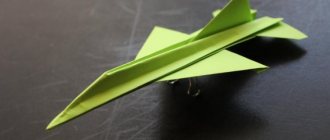
As a child, I was always drawn to airplanes; I remember the first rubber engine built based on some pictures from Soviet MK magazines. Then everything seemed to fade away. Many years later, having already had my own small business and some free time, I remembered my old dream of a radio-controlled flight, but by that time I had no experience in construction yet, and there were problems with the Internet. And then by chance in my city I came across a store that sold a radio-controlled Cessna aircraft with a span of approximately 1200mm. Without hesitation I bought it and assembled it. There was no one to consult with; I did everything and configured it as I saw fit, starting from a rather meager amount of knowledge in aircraft modeling. After probably 20–30 attempts at uncontrolled flight, I realized that either this model was not destined to fly, or “my skis don’t work,” and besides, the model was badly damaged. I set up the Internet, searched through various technologies, pictures, diagrams and drawings and made a decision, which was not easy for me, to remove all the electronics from the Tsesna and assemble my own model using the spare parts received. In the end, I was not mistaken; the new model, made from ceiling tiles and scraps of foam plastic from the TV packaging, took off and flew smoothly, and was controlled adequately and predictably and obeyed control. I experienced indescribable delight and even pride that I could still do something. All year I launched my plane and was happy. The plane stayed in the air perfectly thanks to the V wing, was light in weight and was capable of performing almost any aerobatics. It was on this that I gained my first piloting experience and everything else. What did I do with him! Since then, I have had many models, but the first one I made with my own hands is firmly stuck in my memory and warms my soul when I turn on the video clip that I created for the first time from the footage. However, enough words, now you will see everything for yourself...
§
It doesn’t matter what exactly prompted me to build this model... Maybe an inquisitive mind, maybe a desire to understand the intricacies of working with foam material, or maybe the reason was the three-channel equipment I found in my hands from some RTF aircraft. Yes, it doesn’t matter anymore... It was a long time ago...
I won’t even try to remember from which site I downloaded the drawings, but years later, they remained on my hard drive, covered with a virtual cobweb and pixels of dust until today!))))
(metplaner97sm.zip)
Now, I'm posting these drawings here - I'm sure they will be useful to someone!
Well, before you start building this throwing glider, I’ll tell you how I cost it.
See about copters: Electrical crafts | Country of Masters
DIY radio-controlled boat model. Part 1.
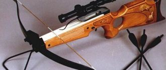
DISCLAIMER: EVERYTHING THAT IS DESCRIBED HERE, I DID MYSELF. IN NO EVENT I AM SAYING THAT “THIS IS CORRECT, WE DO THIS.” THIS IS NOT A BOAT BUILDING INSTRUCTION. I DO NOT HAVE PROFESSIONAL TOOLS OR PROFESSIONAL WOOD WORKING SKILLS. I JUST LIKE WORKING WITH MY HANDS, GAINING EXPERIENCE, CREATING SOMETHING NEW.
It all started in early February, when I accidentally came across parts for radio-controlled boats and catamarans on a well-known Chinese website. I was pleased with their low price, relative to other types of models (until that moment, the idea was to assemble a truggy or a monster based on a 1:10 scale short-course that had been lying on the balcony for a long time. But the prices for the parts were upsetting). And I caught fire. With my engineering thinking I figured out what parts were needed and what needed to be installed. I began to think about how to build a building. Since I have never been a shipbuilder, I started looking for hull drawings on the Internet. After spending several days searching, I was able to find them. If someone suddenly also wants to do something similar, the keywords are “Wasabi900e”.
Full size
900 is the length of the boat in mm. I also saw drawings for 1300 mm for a boat with an internal combustion engine.
I went to the printing center and printed out the drawings in A1 format. The original pdf file is in exactly this format. Everything was printed with millimeter accuracy. (My coursework has never been printed even with such accuracy, even if it was created according to size). We print 2 copies, or better yet 3, just in case. One copy of the main drawing for verification, the second for the stencil. Third - let it be.
Full size
We go to a normal hardware store and look at the plywood. You need plywood, ideally 6mm. I couldn’t find one, but I found 4mm plywood, sawn into 50x50cm squares. Take 2 even(!) sheets. You will also need PVA carpentry glue (I already had universal glue, but later I bought a can of waterproof glue). We also look at a manual jigsaw and files for it.
If you have some kind of special tool for figure cutting, that’s generally great. You have to cut a lot and for a long time.
We are looking for a place to work, preferably a large table with good lighting, and glue the cut out parts from one of the drawings onto PVA. We clamp the plywood to the table with a clamp, and begin reciprocating movements with a jigsaw, and at the same time remembering the drunken worker at school.
I made a model at work. During one night shift I made the bow of the boat.
Full size Full size
A small nuance. The central part, on which the 4mm plywood frames are attached, turned out, in my opinion, thin. It bent easily and was crooked. Glue it onto the plywood, pressing it well over the entire area, let it dry, and cut it out to the same shape as the one already cut out. We get 8mm thickness. Already more serious. We glue the frames, not forgetting that the grooves on them (in the center) are designed for 6mm plywood, they need to be expanded to 8mm.
On the next night shift I did the stern part. The drawing shows that it consists of a lower “board” 6 mm thick. We read the drawing and calculate the length - 441mm. I drew it on paper in advance, glued it to plywood, and sawed it out. We saw the remaining frames in the same way. We glue the keel and frames together, maintaining the dimensions. We do everything accurately so that it is not crooked.
The next step is gluing the body together. Docking occurs in the center. I took a board and put the stern and bow on it. Secure it with electrical tape. Under the nose part, approximately in the center, I placed electrical tape so that the nose was glued correctly and did not look down.
Full size
An important point: in the drawing, on the frames there are rectangular high “ears”. They are needed so that when the boat is turned upside down, it stands on them at the same height. In theory, it should be assembled this way.
In general, the skeleton is ready. The next point is the stringer(s) (I don’t know how to do it correctly) - long longitudinal sticks connecting the frames together. In the same hardware store I took a 10x10 mm bead, 150 cm long. According to the drawing they should be 6x6 mm. I clamp it in a vice and cut off the excess with a utility knife. You can use a plane, but I didn’t spend the extra money, and I have nowhere to find it. We glue them in starting from the stern to the bow, clamping them with a twisted pair wire. We’re not in a hurry to glue the nose yet, there’s a lot of work to do to make it look beautiful.
Making a glider from ceiling tiles
MANUFACTURING A GLIDER FROM CEILING TILES
Korolikhin V.V., additional education teacher, Station of Young Technicians, Glubokovsky district, East Kazakhstan region.
This model is designed for children and teenagers who are beginners to engage in technical creativity circles.
On this model they practice skills in working, balancing the model and launching.
This model can be used for competitions.
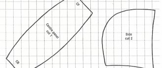
You need to start work by making templates.
The drawings indicate: dimensions in millimeters and a scale ruler is attached, arrows indicate the direction of the fibers of the material.
When printing drawings, the dimensions may not match, so they must be adjusted to the specified dimensions.
The width and length of the parts are important; the radii of curvature can be slightly changed.
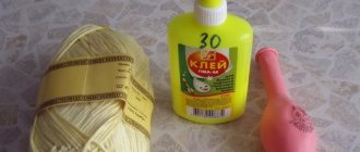
Master glue and titanium are used to connect parts.
An example of making a fuselage sidewall template.
MANUFACTURING FUSELAGE SIDEWALLS
The side panel part is longer than the ceiling slab, so we glue the workpiece together in two parts.
To do this, cut 3 pieces along the grain, 80 mm wide and long for the entire slab, cut one piece in half.
Making cuts at an angle
We place a short blank with a cutout on the long one and make markings on the long blank.
cut out a wedge.
blanks ready for gluing. glued blanks. mark according to the template and
Cut out the sides of the fuselage.
Finished sidewalls, left and right.
The next piece, a strip 40 mm wide and the length of the entire slab,
Curves along the contour of the sidewall.
Glue the insert, control using a square.
Cut out the next insert and glue it to the bottom of the side panel.
The upper insert, from the wide end, is bent along the contour of the sidewall and glued.
The width of the inserts in the nose section is 40mm, from the top bend of the fuselage to the tail section, gradually tapering to 20mm.
The dimensions on the side of the fuselage indicate the width of the insert at a given location. After gluing the sidewall along the contour, a package of ceiling tile plates with a hole with a diameter of 30 mm is glued into the nose part, the hole serves to balance the airframe.
After this, the second side panel is glued.
To fasten the wing in the nose, two slats are installed, oval cross-section 6 mm thick, cardboard washers are used for reinforcement.
The slats are installed 25mm from the top edge
To give the wing a profile, the blank is laid with newspaper sheets and twisted using a pipe with a diameter of 40-50 mm.
Twisting the workpiece
Wing “ears” after twisting to give profile
After giving the profile, the “ears” are cut and the edge of which the “ear” is glued to the wing is ground to give an angle.
The accuracy of the wing assembly is checked on the table by placing the wing on the table and measuring the distance from the end of the “ear” to the surface of the table, the distance should be within 100-90 mm.
A three by five mm strip is glued along the leading and trailing edges of the wing center section.
The dimensions of the wing center section are 130 mm and the entire length of the tile is cut along the grain
The workpiece is cut in half.
Ready assembled glider.
hole for balancing.
There is a hole on the side of the bow for balancing
load, after balancing it is closed with a plug.
Balancing is performed by inserting a weight into the bow through the hole. If the model lifts its nose at launch, you need to add weight, dives sharply, and reduce the weight. A properly balanced model should glide smoothly. The load is fixed with glue.
Schematic model of a glider.
glider toe.
general form
tail unit
Schematic model.
It is made on the basis of the wing from the glider described above; instead of the fuselage, a 10 by 10 mm rail with a length of 700 mm is used.
The toe, made of 10 mm plywood, acts as a weight.
A pylon is glued to the center of the wing to secure the wing to the fuselage.
The pylon is attached to the fuselage using rubber bands.
Balancing is performed by moving the wing along the fuselage.
The sock is made of plywood 10mm thick, 45mm wide, 180mm long.
Technologies for manufacturing foam plastic aircraft.
TECHNOLOGIES FOR TRAINING FOAM CROSS-BASES. All the pitfalls that I came across during the design and construction process took me a lot of time. Maybe my experiences will help you avoid mistakes. And I’ll tell you something new. TITANIUM Glues well to ceilings, paper, wood, and some types of plastic. What I like is the wide range of variations in the gluing process. Apply undiluted to both surfaces to be glued - wait 5 minutes and connect; if you need to grab it right away, wait 10 minutes and connect, it allows you to level out minor unevenness in the gluing areas. It is elastic within reasonable limits, does not tear out the ceiling in case of accidents, and penetrates well into the pores of the foam. The squeezed out excess glue can be rolled up with your finger while it is wet. Rub the plastics with coarse sandpaper before gluing. Can be diluted with pure alcohol. I do not recommend it - it takes a long time to dry. Pouring into any container with a thin spout will increase ease of use. UHU epoxy penetrates well into pores, flowable, easy to mix small quantities, does not harden like “glass” - slightly elastic. I recommend mixing the pieces of paper with the adhesive layer with a toothpick; once you use it, you throw it away. You can take it into the field for repairs—15 minutes after gluing, you can take off. With a glue stick - I glue the patterns to the ceiling; if you don’t smear a lot, the glue remains on the paper (when removed). Masking tape (paper), indispensable for fixing parts when gluing, leaves almost no marks. You can wrap the steering gears and glue them to the installation site. The adhesive layer does not stick to Titanium and epoxy. I don’t like it - if you press hard it leaves matte marks on the ceiling. I have a set of patterns, it is cut at the joints and connected with masking tape, allowing you to separate and put everything together. And a folder for patterns. We take an 8B pencil, the softest one we could find, and mark it. You need to hold it gently and move without pressing, trying not to push through the ceiling, some use felt-tip pens, but they are washed away by alcohol from the glue and it turns out to be dirty. You can cut it directly according to the pattern by gluing it with an adhesive pencil. Or secured with pins. A little subtlety, we cut the radii by moving the knife further and bending it slightly, again holding it hollow. With this cut, the tip goes into the mat, and the cut goes with the middle part of the knife without crushing or tearing the foam. Keep your knife sharp, change blades often! I give an example of a “bully”. “OLFA” blades are black - they hold an edge for a long time and are very sharp. spicy. I apologize for the detailed story, I just want to describe in detail why, why and how I use the tool and technology. Well, okay, let's continue on this topic. I cut out wings from SOLID from two layers (the beautiful side outwards - in general 8mm). They consist of a base and narrow overlays with the rear edge cut off. I apply the glue in thin strips, lengthwise on one part, across the other, I immediately coat the edges to connect the two halves of the wings. We wait 5 minutes and connect, secure with tape on both sides. I make connections with masking (paper) tape like this. I smear the ends and connect them. I glue tape onto one half, stretch it and glue it onto the other half. The plate of course bends, I also repeat it on the other side, and everything straightens out. To guarantee, I press it on top and leave it to dry, after an hour you can continue. I did just that, glued the wings together top and bottom and right and left, all under the load. While it dries you can work on the tail. I cut out two options from 4mm and 3mm. The difference in weight is 1.5 grams. The farther from the center of gravity we carry the weight in the tail, the harder it is to compensate for it in the nose. But out of spite I made 4mm - I shouldn’t have done that. I glue the stiffening rib. I always made it from flat bamboo sticks. In this version I decided to use 1x3mm coal. I clean it a little with sandpaper, increasing the “shaggyness” and wiping it with alcohol. In the stabilizer, I cut a strip along the thickness of the coal, I recommend using a very sharp knife, cutting a 0.5mm gap is quite difficult. Gluing - I apply glue to the cut strip and, without waiting for it to thicken, I immediately insert the coal, which, self-coating with glue, goes deep into the depth. I immediately roll up the excess with my finger or you can smear it by carefully wetting your finger so that the glue does not stretch, but smears. I secure everything with tape on both sides and under a press. I glue a 750x0.5x8 carbon plate into the wing. True, I did this earlier when I assembled and dried the wing halves, well.... I'll tell you the process now. As I already said, it is better to cut through the glue with the ceiling before it is completely rejected. I did it after... it’s difficult to make a slot through glue. I’m showing two options for reinforcement - from the line with lightweights and charcoal, since I haven’t used it before, I decided to try it. I use sandpaper, alcohol and press it into the wing slot filled with glue, showing how to “roll up” the excess glue. Hinge hinges I had a film lying around from a laptop screen; when I sold it, it was glued to the screen as protection. I cut the strip, bend it, this should mark the middle. It is too smooth - I rub it with sandpaper, make holes with a slightly dull needle (so that there are more burrs to increase the gluing power), turn it over and also on the other side. I cut off the strips and rounded the edges to make it easier to insert.
To cut the slits for the hinges, I sharpened the blade of the knife, and now it cuts with the end as well.
I mark the middle according to thickness.
I cut the places, shake the blade up and down a little, it will be more convenient to insert the loops. I smear the edges of the loops on both sides and glue them in without waiting for the glue to thicken. You only need a little glue on the tip - when it “sinks” it spreads evenly, you can fidget with it in a loop. Remove excess glue from the edges and press under. It needs to be glued into the fuselage after hardening for 15-20 minutes. We cut out places in the fuselage, coat the ends of the hinges with glue and diagonally glue in the first, second, etc. and again, without waiting for the glue to thicken. The hinges are slightly tilted to one side (I bent them before), again to make gluing easier. I carefully remove the excess glue, bend the stub back and forth, check how it fits and under the press. Now it’s the turn of the lower part of the fuselage, since it is closer to the ground, I make it from 4mm “SOLID” with a naturally beautiful side towards the viewer. Since the sheet does not include gluing, I place the gluing line above the wing, where it is thickest and strongest. In the tail area there will be a solid beam without gluing. I mark it, cut it, try it on. To maintain verticality, I have foam cubes glued with tape (so that the glue does not stick). On my “branded” slipway I glue everything, fix it with cubes and tape it down. In this case, wait 10-15 minutes for the glue to thicken. I press it and it sticks almost instantly. I slightly modernized the hinge hinges - now I’m making a hole for better bending. I remove excess glue with a cotton swab moistened with alcohol. You just need to do this right away, otherwise it will dry out a little and the glue is difficult to remove. My soft pencil markings can be easily removed with an eraser. Modernization of hinge production. As I said above, in the plastic from which I make loops, I pierce holes for better adhesion when gluing. But sitting and poking with a needle is tiring. Mechanized the process. I took a clock gear and made a piercing wheel out of it, sharpening the teeth. For this purpose, you can also use a wheel with spikes for sewing. They transfer the drawing from one pattern to another. I roll the plastic on one side and it starts to bend; I roll it with the other and it straightens out. A small improvement to inserting hinge hinges into the slot. They are not rigid and bend, and the perforation clings to the edges of the slot. I tilt the aileron down, grab the loop with tweezers by the central slot and insert it. Nothing bends or bends..... survives. I'm making torsion bars for aileron control. The wire is 1.5 mm, heat shrink with a diameter of 3 mm is carefully heated with a hairdryer so that the wire rotates in it. I bend, flatten and sharpen the end of the torsion bar and insert it into the aileron with glue, then I make a groove in the wing and glue the whole thing into it, securing everything with tape. Be careful not to let the glue get into the tube.
I measure the size of the rockers on a machine, cut off the vertical rods protruding from the ailerons to the same length, put on heat shrink, use a servo tester to set the “zero” of the machine and, without breathing, warm it up with a lighter, using a drop of cyacrine for strength. Since the vertical part of the fuselage is already installed, it becomes inconvenient to work. I make a “slipway” from available materials. It will allow you to work with the model (I try to choose the dimensions so that the plane can freely swing its control surfaces). Transport it ready-made. I advise you to handle the plane as little as possible with your hands; the foam is soft; I always move it by holding the slipway. The next stage of my “destructive activities”. I try on and mount the upper vertical of the fuselage-cockpit. I fix it at 90 degrees with cubes with needles and tape. About the mechanism for cutting holes. You can order or buy a special tool, but now I need it and preferably for free. At hand were old capacitors, a can of cosmetics, and a plastic cap from some kind of drink. Aluminum is a soft material, so it doesn’t hold the edge well, which means you need to saw through it rather than cut it. I sharpen the edges and make transverse teeth with a knife, it turns out to be a file. I cut out the holes with rotational movements. Suitable for ceilings. “Pushers” are inserted inside the capacitors to “extract” the cut out parts; by the way, the circles can be used. I am installing the reinforcement of the bow section on TITAN and installing a motor mount made of fruit plywood. I glue it with UHU epoxy. I fix all this with tape. I spent a long time practicing the installation of steering gears, hogs and rods. The proposed method, in my opinion, is the simplest and allows you to completely eliminate backlash and inaccuracies in the installation of steering surfaces. I mark the installation locations of the hogs and steering gears. I determine the length of the rods +2cm. I’ll explain why 2cm later. I make boars from toothpicks, bamboo sticks, and 1.5mm pieces of coal. To strengthen the gluing, I cut out pads from plastic cards and drill 1.5mm holes in them at an angle of 45 degrees. I glue them with epoxy to the steering surface and insert the hog, piercing right through the ceiling. The boar sticks out at an angle of 45 degrees and the top edge should be exactly above the inflection line. The height of the hog above the plane should be equal to the length of the steering wheel rocker arm. I connect the hog and the rod with heat shrink, adding a drop of cyacrine for strength, and make a latch to fix it in the steering wheel rocker at the other end of the rod. Here they are 2cm to prevent them from slipping off the shoulder. And I assemble the entire system “on the fly”.
Now is the most interesting moment. I fix all the rudder elevators in the “zero” position with tape, wrap the steering gears with double-sided tape, set the rockers to zero with a servo tester and, trying not to move anything, glue them to the fuselage. HERE ! Simple and tasteful - the main thing is that your hands don’t shake at the last moment. This entire system can be rearranged from a broken model to a new one, you just need to carefully remove the hog from the foam without removing it from the reinforcement area, clean it from the epoxy and glue it to a new place. In all my accidents, the hogs never pulled out and the rods did not break. Next, I cut out the reinforcement plates for the rear fuselage, try them on, cut the edges at 45 degrees and glue them, again securing everything with tape. This technique significantly strengthens the rear fuselage against torsion. I made two mistakes - the first was miscalculating the aileron rods, they need to be made closer to the fuselage and they would have gone under the reinforcement plates. The second reinforcement plate did not need to be extended across the entire wing to the nose - 1/3 from the trailing edge was enough. I admit mistakes. I make relief holes after the glue has hardened with a NEVEA can. I saw through it quietly right on the model. And also closer to the elevator, I don’t think it’s worth making it any easier. I install the “power” part. I cover the wing with tape - yellow on the bottom, red on the top, overlapping so that two layers cover the leading edge. I glue it to the edge and stretch it lightly, ironing it towards the fuselage, trying to avoid bubbles. Then I realized that it was better to cover the disassembled model with tape. The result will be significantly more accurate. Then I glue everything together. This is where we can finish with the wing. BUT. I wanted more. I decided to lighten it and seal the entire wing. And I glue the ailerons together with the wing. Then I carefully cut the film and run the ceiling plate along the slot, gluing the film to the edges of the aileron. I weld everything with an iron. I fix the plane on the slipway with paint tape. Well, on the front lower part of the fuselage there is reinforcement made of bamboo sticks. I’m making a cockpit. I glue black tape onto the ORACAL film backing, cut it along the radius, stick it on the fuselage and cut it along the contour. Also on the reverse side. You can use blue if you like. I mount the receiver, battery and regulator on a “burdock” secured with double-sided tape. TURNIGY removed the case from the receiver and wrapped it with heat shrink - it was 9.7 grams lighter. Due to the wide nose, the alignment turned out to be carbon reinforced. The flight weight turned out to be 250-280g depending on the battery. I think this is optimal. Not too heavy, not a piece of fluff carried by the wind. Flies normally in winds up to 4 m/s. Modernization of the device, added struts to strengthen the bottom plate (there were constantly cracks along it) and the rigidity of the wings. I installed a motor mount made of 5mm polystyrene foam and 0.5mm “cheeks” on the fuselage. I glued it to the fuselage with titanium, and glued the polystyrene foam together with cyacrine. Good stuff though. Viscous - it holds screws well and is durable, lightweight within reasonable limits. The nose becomes much stronger - the technology has worked out on the gaskets. There were a lot of blows there. A BIG PLUS CEILINGS! Almost any damage can be repaired in a matter of minutes. Here I show it clearly.
Another accident served as an occasion to demonstrate the excellent repairability of foam technology. The tools I have are masking tape, a knife, a pencil, and Titanium. I extend the knife to its fullest extent and cut off the destroyed parts, trying to maintain the plane of the cut. Having attached a piece of the ceiling, I trace the desired outline with a pencil. I spread it with glue, let it sit for 10-15 minutes, and glue it in place. After cleaning the old motor frame from glue, I glue it in place - EVERYTHING!!! The process took 20 minutes. Try restoring balsa-plywood laces in half an hour. One thing...you need to wait until tomorrow until the glue hardens completely. My modernization of the motor mount described above is good. With great difficulty I tore the glue to remove the old motor mount. Well, the blow was not weak - everything was an accordion right up to the wing, and the engine mount holds the engine, as can be seen in the first photo. She never let go. The small airplane "SPRINT" is piloted beyond all praise, very sharp and sensitive. He worked around cutting the grass with a screw. Here is the result. It's true that everything has already been restored. The lawnmower is back in service. Unlimited upgrade possibilities, right at your fingertips. I continue to praise polystyrene foam. My old airplane, proven in combat. I suddenly decided that it was poorly controlled by rudder and elevators. I made a modernization - added control surfaces - glued them directly end-to-end. It holds to death, I can see that the strength of the glued seam is stronger than the ceiling, so you can safely glue it. That’s why I stuck the little wing on, I don’t know, for beauty, probably. Flight of the “little one” In a strong wind, no aerobatics, just having fun “hanging” against the wind. In the distance, the oil depot that I bombed is burning. ABOUT CYACRINE
About the “great and terrible cyacrine.” I worked in advertising and used many different versions of this glue. I settled on German. The glue is very good - it sets instantly under pressure. They can be used to spill joints. The technology of application is as follows: we put a syringe needle on the nose, it is good for getting into inaccessible places. Use a thicker needle. And the glue still hardens in the needle; there are two options to eliminate this. When I turn the tube upside down, I squeeze out the glue, without releasing the pressure, I turn the tube upside down and release my fingers; the remaining glue is sucked out of the needle. If it still freezes, I heat the needle in the flame of a lighter - the glue burns out - after cooling, you can use it. Cyacrine hardens due to humidity. If you need to quickly glue, breathe “wet” on the glue. DO NOT INHALE GLUE VAPOR!!! In the presence of humidity, it instantly hardens, but forms a matte coating. If you need a lot of glue - for example, to glue something with large gaps - I drip the glue and sprinkle with baking soda, and again I drip and sprinkle. The result is a kind of plastic - with the release of heat.
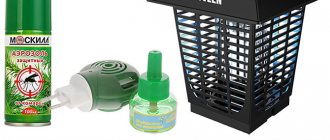
SECURITY MEASURES!!!! I ask you to take this point very seriously; I myself witnessed all sorts of incidents and I am warning you. If your fingers or skin are stuck together, do not tear them!!! Place it in warm water and after about 10 minutes it will sweat and come unglued. DO NOT breathe in vapors - if there is a large consumption of glue, there must be good ventilation - it causes allergic reactions - redness and “sand” in the eyes. In case of serious poisoning - a dry cough - similar to a cold - which cannot be treated with anything - anti-allergic drugs may be slightly relieved. I coughed for a month and a half. If it gets into your eyes, call an ambulance immediately!!! One big BUT, it corrodes the ceiling. I continue the topic of technology. There was a need to balance the screws - I looked through stores and forums - everything was interesting and... expensive. I bought a simple balancer. 140 rub. To get a feel for the topic with your hands.
I installed all this manual miracle on a magnetic suspension. And then it turned out that... the balancer itself was not balanced. Its clamps are poorly made—or rather, the “holes” are drilled inaccurately. Its only advantage is that it clamps well with eccentrics. All this can be done simpler - I take several axes that exactly match the diameter of the screw hole and sharpen the ends. This is done simply, I clamp the axle into the drill, turn it on and bring it to the sharpening disk, or a diamond one. And it turns out to be a cone, quite exactly in the center of the axis. The magnets were taken from the speakers. This is how the screw turns on a homemade axle, the breeze blows from the window. My “comrade in the struggle” advised me to make another device. So I listened and this is how the thing turned out. I put a level on the blades and adjust “0” with three screws. I balance by simply gluing a strip of “oracal” onto a light blade. In this way, so that it goes around the front edge, there is less risk of it coming off. Some sand a heavy blade. Well, as you like.
In my opinion, this device is more accurate. Thanks for the advice.
For soldering and working with small things, I secured a magnifying glass for myself. A leg made from an old lamp, a magnifying glass from an enlarger, I don’t remember what brand. The frame was made from a strip of 5mm polystyrene foam. He heated it with a hair dryer and quickly wrapped it around it. On the front side there is a higher side to reduce side glare and black matte paint for the same.
VILLAGE TECHNOLOGIES. Razor blade holder. It cuts the ceiling much better, due to the thin blade, you can cut a very thin strip for reinforcement, for example. I cut the razor in half with scissors and cut off the dull tip as I work. I bend a strip of stainless steel two centimeters wide in half. The same strip is put on the bottom and holds the blade.
Precautions when working with coal and fiberglass. Work only with gloves; if you wear long sleeves, you can put them in gloves or in a respirator. Take care of your loved ones. After the process, wash your hands for a long time in cold water, washing away microsplints. If it itches, don't itch! Wash again. After five water procedures, my hands stopped tingling. And it is advisable to rinse the slats in cold water, wiping them with a brush, so as not to pick up splinters later. The simplest “splitter”: From polystyrene foam and a knife blade, I glued everything together using cyacrine. For a specific size without any adjustments.
The splitter is the size I need. Not only coal, but also other slats can be cut. The base is a thick piece of polystyrene foam - under the blade there is a lining of the required thickness and everything is fixed with self-tapping screws. Make the back edge of the blade slightly raised so that the sharpening plane is parallel to the base. When splitting, the resulting surfaces are slightly rough and adhere very well.
Ceiling router. A milling cutter for the ceiling from whatever came to hand. And I came across a plastic pestle, which is used to push meat into a meat grinder. It fits tightly onto the drill. I adjust the depth manually by raising or lowering the attachment. I cut with a dental bur with large teeth. If you set the rpm to a maximum of 15,000, it cuts quite cleanly. First, I prepare templates for milling. I place it on the cut-out piece and trace it with a pencil. I will guide the cutter according to the drawing. This is the result of destructive activity. I made a simple “feather” cutter. I sawed a groove in a nail of a suitable diameter, inserted a piece of blade from a stationery knife into it. At work there is spot welding, I grabbed it a little, trying not to burn the blade, and sharpened it vertically. I sharpened the opposite vertical edges using sandpaper and straightened them using “zero” sandpaper. Well, just a song. It cuts quickly at the maximum speed of the drill. It makes sense to lighten it, of course - minus 10.5 grams gone. But everything was in small electrified shavings of foam plastic - it was just terrible, there was nothing to clean it up, it stuck to everything. Somehow I cleaned everything up with a vacuum cleaner. It's good that I did an experiment at work. At home they would have killed me, or I would have shot myself. We need to come up with something - maybe bring a hose from a vacuum cleaner. The shavings were thrown out of the work area and thrown out well, even very well. Another modernization of the milling cutter. I glued a transparent gasket from the disk box to the base in order to increase stability and the ability to mill large holes. I brought a plastic tube to the cutting head - I bought a building level in the store. I made a foam plug with a hole in the vacuum cleaner pipe. It is better to use a vacuum cleaner with a regulator. The chips are successfully removed. You just have to drive it slower so that everything is absorbed normally. A small detail, so that there are no burrs, the router must be driven clockwise. You can use cutters for CNC machines. They cut very well. For example. https://neotec.ru/ru/main/catalogie/onsrud/product148.html Slipway. When one vertical edge of the fuselage is already glued and you need to work on the opposite surface. I show you how I use it. Motor mounts and nose reinforcement. On the motor mount. As I already wrote, now I make motor mounts from polystyrene foam. Between the frame and the engine I put a gasket made of a rubber tube. Firstly, it dampens vibration, and secondly, it makes it easy to adjust the slope. There is a photo of the first version of the shock absorber. I’ll show you where I tore it from, there are also axles with a diameter of 3mm, which will also come in handy. Determination of C.T. I try to use everything that is at hand for the benefit of aircraft construction. I came across a tabletop hanger for kitchen tools, I cut out the middle with all sorts of hooks for hanging and it turned out to be a balancing machine. It’s really not cool, without a level, a micrometer and a GPS navigator. But the center of gravity doesn’t really care how they look for it, for 500 bucks or for nothing. I made myself a battery pack for the transmitter - soldered it together and wrapped it in an oracle. Inside there are eight 1.2V, 2700mA batteries that were given for free. This assembly lived for two years. It is not always possible to fully imagine the layout of individual structural elements. Even if I think it over and draw it.
When your brain completely jams. I'm making a three-dimensional layout. It can be made from paper, cardboard and even plasticine. JEWELRY technologies at the service of aircraft modeling. There is a good tool in the jewelry store. https://www.ruta.ru/
for example, a jigsaw and metal files, they cut plywood very well https://www.ruta.ru/product/224120_lo...glubina_80_mm/ They go by numbers, the lower the number, the smaller the tooth and the more teeth per centimeter. And there are all sorts of wire cutters, small pliers, non-magnetic tweezers, needle files, in general a bunch. And of good quality. A few years ago I collected several thousand of all sorts of nice little things, I’m still happy, very... good tool. https://www.ruta.ru/products/ruchnoi_...ii_instrument/ Section of hand-held cutting tools, I would buy everything with my eyes...., first, all sorts of burs, I go further to the end of the needle file, in my opinion, metal files start from sheet 30. Optics. I bought these magnifiers about 7 years ago, a convenient accessory, no match for our options. It fully justifies its price. You need to look at the focal length of 500mm, this is your nose to the plane, well, you know, 150mm is not enough. https://www.ruta.ru/product/214201_oc...oyanie_500_mm/ There are dies and taps for small diameters.
https://www.ruta.ru/products/ruchnoi_...ment/?&page=33
Here the dies begin.
An undeservedly forgotten drill, very well suited for thin drills, as well as carbide drills that break easily, there are different options.
https://www.ruta.ru/product/223053_dr...annoi_ruchkoi/ https://www.ruta.ru/product/223057_dr...alaya_L_95_mm/ https://www.ruta.ru/product/223058_dr...inoi_L_100_mm/
Please pay attention to the lubricant, it is used when sawing or drilling some nasty viscous material. For example copper or soft aluminum. Increases the sliding of the drill and file and prevents clogging. There are other options out there, look for them.
https://www.ruta.ru/product/223069_un...i_borov_50_ml/
You can also use wax, only real wax from bees. And not from candles, at best there is stearin or some kind of nasty stuff in general.
In short, I’m constantly grazing there, grabbing a little something. OFFICIAL DISTRIBUTOR 3M https://www.politape.ru/catalog/1/ This is our section, the prices are of course not very affordable, but the quality is super, gold and turbo. What other fashionable words are there today, 3D and nano tex. I took tape there, Velcro Velcro, it sticks to death, you can only tear it off in pieces. https://www.politape.ru/catalog/23/740/ There are good spray adhesives for gluing the film to the frame. for example https://www.politape.ru/catalog/20/444/
I use this glue for gluing stencils when painting.
https://www.politape.ru/catalog/20/443/
well, packaging and reinforced tapes
https://www.politape.ru/catalog/30/
The advertisement says silent adhesive tapes.
The best thing is to cover the floor of the plane with a blanket at night. No one will hear. That's it, it seems. I talked about the intricacies and difficult places of production that were not included in my previous articles. I have already written about the construction of my own aircraft and the technologies are described there in sufficient detail. I won't repeat it. Read it in my diary. I apologize to the pilot brothers, there are no detailed drawings of my aircraft. During construction, I started from the idea and made minimal calculations and drawings. I will try to prepare at least some according to your requests. But still, “printing and gluing” will not work. You'll have to remember a little about drawing, work with a ruler and a pencil. I give you ideas and techniques, use them when building your planes, improve them, remake them. Let it be easier and simpler for you. OLEGSS Who is interested, read my writings in the diary.
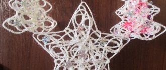
Ceiling glider for little ones
I was sorting out some information on an old propeller and found a selection of drawings for making free-flying gliders.
These aircraft models are easy to make, do not require any skills, and they are not radio-controlled models.
It's just a glider.
The drawings are scans from Polish magazines; in the original they were proposed to be made from balsa, but they would also work great from ceiling tiles.
Actually, this collection of drawings (you can download the glider drawings at the end of the article) is intended for aircraft modeling clubs for children. These still exist in schools.
You can build them just for fun with your child