Unfortunately, lately, dynamos for bicycles have been undeservedly forgotten. We will not delve into the reasons for this, but rather make a headlight for a bicycle with our own hands, powered by a dynamo generator.
Advantages of dynamo-powered LED bicycle lights:
- powerful beam;
- constant availability of power (batteries can run out at the wrong time);
- unlimited work time;
- no need to replace batteries or charge batteries.
The design of this type of flashlight for a bicycle is described on this resource (it is recommended that you read it): link
Let's start assembling
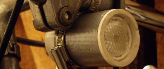
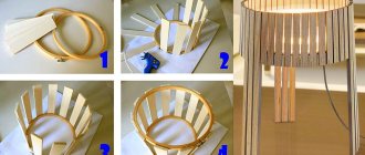
Let's look further at how to make a bicycle lantern with your own hands. First, fix the lens in the front of the body using hot glue. Hot glue is the most reliable option, but if this is not available, you can use a good superglue and subsequently seal the remaining cracks with sealant.
Attached bicycle light on the handlebars of a bicycle
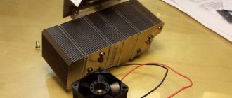
At some distance from the lens, install the LED, having first secured it to the radiator. You will need to drill holes in the radiator to route the wires out. At this stage, you need to power the device and find out what distance is optimal. Test your flashlight in a dark room, directing the beam of light at the wall - this way you can most clearly evaluate the result.
Fix the radiator in the desired place. Depending on which case you managed to select, choose the mounting method. Perhaps the hot melt adhesive will not be enough, then you will have to drill holes on the sides and secure the radiator with screws.
Now you need to install the back cover of your flashlight. If it is not provided in the case, you can cut it out of a piece of plastic. There must be a distance between the radiator and the cap. Attach the batteries to the inside of the cover and the switch to the outside, connecting it according to the installation diagram for your LED. Place the cover on the housing. It is best if the cover is secured with screws, then it can be removed to replace the batteries.
Making a bicycle lantern with your own hands
The bicycle spare parts market is replete with various flashlights and headlights, but it is always more pleasant to make such a part yourself. Moreover, it is not too complicated and also gives room for creativity: you can choose the color of the beam, the size of the body and the mounting method, adjust the strength of the glow, etc. You will learn how to make a headlight for a bicycle in the following instructions.
Bicycle light
Rear bike light upgrade - DRIVE2
I'm not a great cyclist, and riding on the roads is scary. So that they could see me from afar, they gave me a Cyclotech XC-998R bicycle flashlight that year.
The flashlight is just like a flashlight, nothing special: a button and a flasher with five LEDs. You’re driving along the road and she signals to the drivers: “Look, there’s someone here!” - beauty!
It’s just that you have to turn it on, then turn it off, it’s all so lazy!
Last year's cycling season ended, but all winter I was haunted by the thought of this pressing of a button.
“Am I a programmer, or where?” — I thought, “After all, you can make it turn on and off on its own.” And I set about redoing it.
The idea was to place an accelerometer on the board, and when the bike is in a parking position and does not undergo vibrations, turn off the light, and when it vibrates again, turn it on.
Accelerometer selection
The entire structure is powered by two “little finger” batteries, that is, the voltage varies from 1.8 to 3.2 Volts. The accelerometers I had did not want to work at such low voltages.
For example, LIS331DL wanted to have at least 2.16 Volts at the input, and MMA7660FC wanted 2.4 Volts.
At the same time, the first wanted to consume as much as 300 microamps at a frequency of 100 readings per second, and the manufacturers of the second naively considered its gluttony at the level of 47 microamps at a frequency of 1 reading per second to be an advantage! You can’t cook porridge with such porridge, you won’t save batteries.
And then, accidentally skimming through the catalog of a local radio parts store, I saw LIS3DH
for only 78 rubles. After reading the document on the device, I jumped with delight, because this is exactly what I was looking for! - Operating voltage: 1.71 - 3.6 Volts - Bit depth on each of the 3 axes: 16 bits - Reading frequency: from 1 to 5000 V give me a sec.
- Current consumption in sleep mode is 0.4 µA, at 10 per second - 4 µA, at 200 per second - 38 µA. This is not counting the low power mode, which reduces accuracy, but also reduces current consumption!
- In general, I collected my belongings and rushed to the store to buy such a thing.
- Microcontroller
Since I only know how to tinker with AVR, there is not much choice. But since we are talking about saving batteries in standby mode, the choice fell on pico-power devices, in particular the ATmega88PA-AU.
In fact, at the beginning the choice fell on ATmega48PA-AU, but at some point my wishes did not fit into 4 kilobytes, and I resoldered it to 88.
LEDs
I also decided to replace the standard LEDs with super-bright Cree C503B-RBN, for which they promise as much as 10 Candelas at a current of 20mA. Although their lighting angle is 23 degrees. But we don’t need to throw around corners - the LEDs shine mainly backwards, and the two at the edges shine to the sides.
- Making entrails
- First, all the original contents of the lantern were shaken out, unsoldered and disassembled:
- In the standard version, all that is there is a small microcircuit on a small scarf, to which power and a signal from the button are supplied.
Then I made exactly the same size (except for half a millimeter thicker) boards. But this time the microcontroller is placed on a large board, and on the small one there are only tracks to the LEDs. Therefore, where they are attached to each other has become a little more difficult. At the same time, I strengthened it by soldering on the reverse side.
I did everything using the “LUT” method. Then I tinned everything with a soldering iron except the space under the button, and soldered the elements.
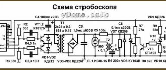
The circuit is simple, not counting a pair of capacitors and five resistors (which, by the way, could be done without - since the voltage drop at the MK terminals just well limits the current at the required level), only the MK and the accelerometer are present in the circuit.
Large rectangular pads are for soldering the programmer connector. There is no place to place a full-fledged connector here, so here it is.
And this is what everything looks like assembled:
Pairing the MCU and the accelerometer
They interface with each other via the SPI bus, and on the MC side, USART is used in SPI master mode. The accelerometer can operate on both the SPI bus and the I2C bus (aka TWI in AVR terms).
But I2C requires pull-up resistors and data transfer involves quite significant current leaks - up to two milliamps, depending on the exchange rate. You can't get enough batteries for this! In addition, I2C operates at a speed no higher than 400 kHz, and is much more difficult to implement.
So the choice is obvious - SPI. But these MKs have regular SPI and it is possible to use USART in SPI master mode.
Since one of the SPI pins is also a PWM output, and it is used on the LED, the USART remains.
Additionally, I connected the INT2 interrupt. I messed up a little with this: as it turned out, this accelerometer model, unlike its brother LIS331DL, cannot display a sign of readiness for new data on INT2, only on INT1. However, the problem was successfully solved using software.
Acceleration measurement
In active mode, the accelerometer operates at a frequency of 200 readings per second, in the range -2g...+2g. From it comes three 16-bit signed numbers, each of which encodes acceleration along one of three axes in this range. Accordingly, +16384 corresponds to an acceleration of +1g.
So, we are bombarded with a flurry of readings, any small vibrations and shocks are marked by a sharp, short burst of acceleration along one axis or another.
To determine the overall acceleration trend, you need to get rid of these spikes. In other words, apply a low-pass filter.
Since we are limited in computing power, the filter should be quite simple. This option is suitable for each of the three axes:
F = Flim + (V - Flim) * k
,where F is the new filter value, Fpre is the previous value, V is the new value from the accelerometer, and k is a positive coefficient less than one.
The smaller k, the lower the cutoff frequency. The multiplication operation can be replaced by an arithmetic shift operation, for example, if k = 0.25, then the multiplication will be replaced by an arithmetic shift to the right by two positions.
Next, we are interested in determining the vibration tendency: whether the bicycle is standing still or rushing with a rapid jack. To simplify the calculations, the following algorithm is suitable: For each axis, take the module |V - F| - this is precisely the module of the high-frequency component. The maximum among all three axes will be considered the current vibration.
If we take the current vibration value and pass it through the filter using the above formula, we will have a filtered value that shows the current vibration trend.
Processing algorithm
So, having received the next readings from the accelerometer, we pass through the filters described above, we get the filtered acceleration, the current vibration and the tendency to vibration. When these readings go beyond the established limits, we turn on the meter. If for several pieces of data in a row the readings remain outside the permissible limits, then the event being assessed has occurred.
- For example, if along the longitudinal axis, for 4 readings in a row, the filtered acceleration value exceeds 0.2g, then braking is applied.
- And if for a second in a row, the acceleration along the horizontal axis is more than 0.5g, or the acceleration along the vertical axis is negative, then the bicycle has fallen.
- Implemented functions
Bicycle headlights, headlight review
Bicycle headlights have a variety of designs and differ in appearance.
They also have different mounting methods and types of lighting. There are two types of bicycle lights:
1. Headlights.
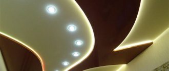
They perform lighting functions and indicate cyclists on the roadway at night. However, not every lighting fixture is bright. LED headlights are very common nowadays, they really illuminate the path well and provide good safety for the cyclist. Xenon headlights are also used, but they are very expensive.
2. Rear lights.
These headlights operate in two modes - constant and flashing. They serve as a cyclist identification for those riding behind him at night or in difficult weather conditions. Very often, LED taillights are used as these accessories.
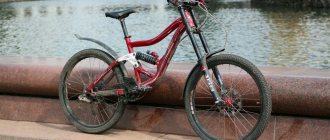
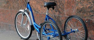
Bike mount
We figured out how to make a flashlight for a bicycle, now you need to attach it to your vehicle. The easiest way to do this is with a regular plastic clamp. Drill the body of your device on both sides closer to the back wall, preferably where there is a distance between the radiator and the back wall. Thread a plastic clamp through the resulting hole and tighten it to a convenient location on the handlebars of your bike.
Bicycle flashlight
Ready! You made a flashlight for a bicycle with your own hands. The time has come to thoroughly test it in evening driving conditions. Don't forget to take a regular hand light with you in case something goes wrong and your new bike light needs some work. Good luck on the roads!
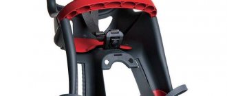
Where is the best place to attach a homemade light?
There are 3 zones for fastening, each of them has its own pros and cons:
- A flashlight is most often found on top of the steering wheel, the pluses are the range of the light beam, and the minus is the angle of incidence
- At the connection between the fork and the handlebar, the pros are good visibility, but the minus is an unclear light beam
- Two lights on different sides of the fork, the pros are good lighting, the minus is that you can blind the driver ahead, block his rear view and increase his blind spots.
All these nuances are very easy to solve; the main thing is to correctly select the power of the lighting elements and choose the optimal mounting location, based on the design.
To increase safety, it would be a good idea to attach a small light to the back of the bike so that drivers can see you better at night.
Simple making guide
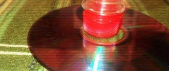
The aluminum disk will be installed inside the case; 3 holes are drilled in the disk in advance - 2 for wires and one for the LED, which will be secured with hot-melt adhesive. We install capacitors near it. The lead-out wires are connected to the battery, then a lens cut to the diameter is inserted into a plastic elbow or pipe and secured with hot-melt adhesive.
All wires must be insulated! Such a simple device will become an integral part of the bicycle.
About a cheap flashlight for the steering wheel
Well, a little about that cheap flashlight. Probably the cheapest I came across on Ali. Today the price is something like 250 rubles including delivery. Link to the seller (large number of orders, high rating).
The ridiculous price of three dollars made me think that this was a useless toy. But I was surprised to find that the lantern deserves attention. And I’ll even keep it for myself, because it will definitely have a use in cycling.
Manufactured in an aluminum housing. Such cases seem to be produced by some very large factory in China, because they have a lot of analogues, and they are very inexpensive.
Built on diode Q5 (less powerful and less bright than T6 and especially U2).
The weight of the flashlight without battery is 47 grams, with the mount - only 84 grams.