Communities › Homemade Garage Hi-End › Blog › Hydroelectric station
As they say, “due to business needs,” a need arose in production for a hydraulic station from which various hydraulic tools could be powered: hydraulic cylinders, presses, sheet benders, hydraulic motors, etc.
In general, this project has been brewing for a very long time, the first parts for it were purchased two years ago, but since there was no urgent need for such a device, the project remained in a dormant state. However, its time has come... This is one of the few projects that we built without any preliminary drawings. As they say, in place and from scraps. To be honest, this is hell (although almost everyone I know works this way). On the one hand, it seems like progress is immediately visible, but you also have to redo it 100,500 times, because you don’t foresee one thing, then you forget another... But you can feel like an Artist.
The engine was 2.2 kW at 1400 rpm (AIR90L4). The use of NSh type pumps was immediately abandoned due to the unclear situation with their quality and the real chances of running into outright defects. Instead of the NSh, we used a Taiwanese pump RG P2 with a displacement of 4 cm3, delivering a pressure of 250 bar (which is 1.5 times more than that of the NSh). The pump was connected to the engine through an adapter bell and a coupling with a polyurethane insert, fortunately all this stuff is standard, easy to buy and does not require any manipulations like “cut a piece from one part and weld it to another,” as happens with NSh.
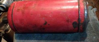
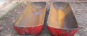
Under the engine, we welded a mighty frame from 80x40 channel bars, the remains of which were gathering dust lonelyly in the corner. Cutting sheets 2mm thick were used on the tank.
We assembled everything first on oven mitts. Firstly, it’s easier to redo everything when something goes wrong (and I had to redo it often). Secondly, this is a way to force yourself to paint the product before using it. Usually, when everything is already assembled, there is no desire to disassemble everything and paint it, so half of the devices in our workshop can serve as sets for a film about a post-apocalyptic future. And when assembling on tacks, everything will have to be disassembled for welding, and at the same time painted.
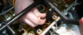
We figured out a panel for installing the hydraulic distributor. We only had a single-section one in stock, but in the future there are thoughts of putting a distributor into 3 sections in order to get 6 working circuits and be able to connect up to 3 consumers to one station (one day this will definitely be needed).
Next, we installed the main filter and found a place for the starter to the engine. At first, they thought of placing the ports for connecting hoses next to the distributor, but then it became clear that this was not a very good idea, and in the final version everything moved down to the wheels
We put the device on wheels and began to figure out how to connect the hoses. This is where all the shortcomings of the “artistic” approach came out. Hydraulic hoses are quite rigid, so it is not always possible to connect them as originally intended. After some torment and alterations of the hoses, everything was connected like this.
Literally it immediately became clear that this was not a very successful configuration, and the BRS was moved downstairs. Otherwise, almost a meter of hoses of the connected tool would be “eaten up” due to the fact that the connection point is too high above the ground. The configuration was revised, and the BRS moved downstairs.
Then everything was disassembled, scalded, sent for painting and we suffered for two whole days waiting. Finally it's time for the final assembly.
DIY manual hydraulic pump
The hydraulic (manual) pump is quite in demand in the industrial sector. Its main task can be called pumping fuels and lubricants.
At the same time, the models have their own permissible viscosity standards. Additionally, the devices differ in their design. The main element of a hand pump can be called the dispenser pipe.
In some cases, telescopic intakes are used instead.
How is it built?
The standard manual (hydraulic) pump has a simple device. There is a test hose located at the bottom of the housing. It is attached to the mechanism through a special hole using clamps. There is a valve higher up in the hand pump that controls the pressure. By turning it clockwise, you can adjust the pumping force.
There is a plug for filling the tank. Below it is a small port, which is designed to connect to the general system. The mechanism also has a separate reservoir with a pipe for liquid.
The hydraulic cylinder is connected to the hand pump using a threaded method. To adjust the valve intensity, manufacturers install special regulators. With their help you can easily change the pressure.
In this case, the pump handle is installed separately, which is secured with a plug.
Diagram of a hand pump for pumping out oil
To pump out large quantities of oil, a durable hydraulic cylinder is required (a diagram of a manual hydraulic pump is shown below). As a rule, it is reinforced with a small support. As a result, it is possible to secure it more tightly. Additionally, bolts are used for this.
Among other things, the hand pump is equipped with a hydraulic tube. Its main task is to supply pressure to the cylinder. For this purpose, a tee is installed in the device. It is mounted on a special cushion, which is fixed on a washer. It is also secured with nuts. A rubber band is used for the holder in the hand pump. In this case, the fitting is located at the very bottom.
Pump repair
In order to repair a hydraulic hand pump, you need to find out as much as possible about the breakdown. First of all, you should look at the pressure gauge readings.
If the pressure deviates from the norm, this is due to the central reservoir, the tightness of which may be compromised. In order to replace it, you will need a standard set of tools.
First of all, unscrew the upper bushing and disconnect the hydraulic pump handle. Next, you need to carefully remove the protective washer.
After this, it is possible to disconnect the plug. Directly below it is a reservoir. If external inspection does not show obvious deformation, the shut-off valve must be unscrewed from it. After this, experts advise checking the functionality of the valve. If it is quite tight, you need to lubricate it. After this, the mechanism should be folded and checked for functionality.
The second common problem with pumps is considered to be abrasion of the rubber plug. In this case, you can simply replace it. In this case, it is necessary to find out its exact diameter and thickness. After completing the repair work, the entire mechanism also needs lubrication.
How are homemade models created?
Today, homemade devices of this type are quite rare. However, you can make a hydraulic pump (manual) with your own hands. First of all, a steel tank is used as a body.
It requires a valve to control the pressure. It is secured at the top with a washer. A lever is used to adjust the shut-off valve. In this case, you can use a cast iron pipe.
To control the pressure, a pressure gauge should be installed.
You will need a sleeve with a pipe that will prevent the valve from twisting. As a result, you can fold a device that can withstand a pressure of no more than 4 atm.
A distinctive feature of homemade hand pumps is their large dimensions. And to bring the lever into operation, great efforts must be made.
Considering all of the above, such devices are considered ineffective and are rarely used in industry.
Hydraulic pumps NRG
HP pumps are reliable pressure sources. Moreover, they can be connected to various hydraulic systems. The manual hydraulic pump NRG-7007 has a nominal tank volume of 0.7 liters.
At the same time, its useful volume is 0.6 liters, and this modification can withstand a pressure of 1.3 MPa. Overall its performance is pretty good.
If we consider high-pressure pumps, then the NRG-7110 device deserves attention.
Its nominal tank volume is 1 liter. In this case, the maximum pressure is maintained at 2.7 MPa, and the force on the handle must be applied at 50 kgf. The dimensions of this modification are as follows: width - 310 mm, height - 320 mm, and length - 750 mm.
The hydraulic pump (manual) NGR-7016 has a nominal tank volume of 16 liters. At the same time, its useful volume is 14 liters. The pressure at the first stage is maintained at 2.7 MPa, and the system capacity is 113 cubic meters. see in one move.
This hydraulic (manual) pump weighs as much as 29 kg.
NRG pumps with distributors
Hand pumps of the NRG series are produced in some cases with distributors. These models have the letter “P” in their names, so anyone can recognize them.
A distinctive feature of these devices is considered to be high maximum pressure. Moreover, their tanks are installed in a variety of diameters.
If we consider the modification NRG-7020R, then the useful volume of the chamber is exactly 2 liters, and the pressure is maintained at around 3 MPa.
The productivity of the device at the second stage is 113 cubic meters. see the move. In this case, the force on the handle should be applied at 55 kgf. This hydraulic (manual) pump weighs 22 kg.
If we consider the NRG-67016R model, then its nominal tank volume is 14 liters, the “maximum” pressure is maintained at 4 MPa. The capacity of the mechanism at the second stage is 115 cubic meters. cm per move.
The assembled device weighs exactly 30 kg.
Single acting system
To connect a manual hydraulic pump to a single-acting system, you will need a special adapter. It is usually let in with a pressure gauge.
The most common modification of the adapter is considered to be the “MA100” model. Additionally, you will need a hose at least three meters long. Its end must connect to the coupling half.
The system must also have an actuator.
A distinctive feature of these devices is a powerful valve that can withstand heavy loads. It is connected to the system, as a rule, through a regular adapter. Additionally, a BRS class half-coupling is used. To work, you will also need an adapter that will be attached to the tap. Via an adapter, the pump can be connected to the actuator.
Double acting hydraulic system
A double-acting hydraulic system requires a standard adapter as well as a pump. In this case, the coupling half is used from the BRR series. It should also be noted that the rod can be connected to the system, and this is done to return the stroke.
By default, it is assumed that there is one hydraulic pipe, but several can be connected. In order to connect the pump to the actuator, a special hydraulic lock is used. It is installed on two connectors at once.
In this case, the pressure can jump to 3 MPa.
In this case, you should constantly monitor the pressure gauge readings. After installing the hydraulic lock, you need to tighten all the bolts and check the rod for functionality. Additionally, it should be noted that protective bushings in this system can only be used of the UGZ class. This is due to the fact that it is necessary to connect to the actuator with exactly two connectors.
How do hand pumps operate from a station?
The hand pump can only be connected to the station using an adapter of the ШП series. In this case, the standard connection diagram provides for the presence of a drain pipe. It is produced with the “T” marking.
Additionally, you will need a valve that will regulate the pressure. The coupling half of the device is directly attached to the second hose. In this case, the central rod is not used.
This is due to the lack of a hydraulic lock.
Ultimately, the system must be closed on the actuator. In order to check the functionality of the pump, the valve should be fully screwed in until it stops. Next, the actuator is turned on. At this time, the pressure gauge should not show pressure. If any problems occur, you should completely check the circuit for integrity.
Design of pumps with half-coupling
A feature of pumps with a half-coupling is considered to be volumetric cylinders. At the same time, they are attached to the camera using special clamps that are fixed with bolts. Additionally, there is a protective washer that locks the central rod. Directly below this is a small tee that connects to the hand pump sleeve.
Design and purpose of a manual hydraulic pump, technical characteristics
style=”display:block” data-ad-client=”ca-pub-9337857885889635″ data-ad-slot=”9967522739″
data-ad-format="auto">
Manual hydraulic pumps are quite versatile devices, the main advantage of which is high transportability, as well as the absence of the need to connect to the electrical network. This factor makes it possible to operate high-pressure hydraulic pumps for both domestic and industrial purposes.
The hydraulic water pump has the following design:
- Working handle. The main means by which a person transfers mechanical energy to the pump device. The handle is a kind of lever mechanism, the influence of which regulates the intensity of operation of the pumping device. At the same time, some pumps, for example, manual hydraulic pump 101, can be equipped with an additional foot rod, which facilitates human effort and promotes operating comfort;
- Plunger. A connecting element that acts as an intermediate link between the handle and the body;
- Pump housing. The body of the device is also a detail of primary importance, because it is in it that a vacuum is created, which transforms into pressure of the required degree, with the help of which the liquid is taken and pumped. The HP hydraulic manual pump is equipped with a metal or plastic housing that has hermetically sealed insulation. The hydraulic oil pump has an additional oil composition that optimizes the operation of the device;
- Case back cover. It provides additional fixation of the housing, and also helps to create the necessary pressure in the system;
- The bleed valve is a unit that helps normalize pressure. The manual hydraulic pump NPG 7007 has a vertical valve arrangement on the back cover. Other models may be equipped with this part either in the same place or on the back/side of the pump;
- High pressure hose. It is clear that only a manual high-pressure hydraulic pump has this device. The sleeve is a hose that is attached directly to the plunger, and is equipped with a special connector at the opposite end;
- A pressure gauge is an optional device that can be used to monitor the technical characteristics of a hydraulic hand pump, namely the pressure level in the system.
The main technical characteristics of hydraulic pumps are the pump operating pressure and displacement. Working pressure is an indicator of the power of the device.
The higher the operating pressure, the faster a manual hydraulic pump can pump fluid. Pump pressure is measured in a special unit - Bar.
Hydraulic pump
The hydraulic characteristics of pumps in the form of working volume will indicate the amount of water mass that the pump is capable of pumping in one full cycle of operation. Pump volume is measured in cubic centimeters.
Operating principle of a manual hydraulic pump, scope of application
A hydraulic cylinder with a hand pump has an operating principle that is based on the transformation of mechanical action into hydraulic force. In more detail, when the handle is pressed, pressure arises in the pump.
After this, due to the existence of a suction and discharge compartment in the design of the hydraulic pump, liquid is drawn in. At this time, the valve normalizes the pressure in the system, and further transport of water occurs due to the vacuum.
Manual hydraulic pumps Gn operate in the same mode until human impact stops.
In the body of the device, a constant friction process occurs, so the oil chamber helps protect the internal parts of the pump.
The hydraulic manual pump NRG 344 and models of a similar design are primarily intended for use in summer cottages and country houses, for the purpose of pumping water and other liquids from a certain area. Such pumps are also used for local transportation of liquid to a designated place.
Hydraulic manual pump 20 tons, also used on an industrial scale.
Such pumps are capable of working with more aggressive media.
They are actively used in the construction of both small projects and large office centers and apartment buildings.
Types and differences of manual hydraulic pumps - their prices
style=”display:block; text-align:center;" data-ad-layout=”in-article” data-ad-format=”fluid” data-ad-client=”ca-pub-9337857885889635″
data-ad-slot=”9725334793″>
High-pressure hydraulic pumps may differ in their design, device features, as well as technical parameters.
Manual hydraulic pumps, depending on the working position, are:
Hydraulic submersible pump. This design is more powerful, designed to work with a depth of 10 - 15 meters.
The working part of the pump is located directly in the liquid, and the working handle itself is directly on the source.
The 10t manual hydraulic pump is one of the representatives of these pumps.
Most often, a hydraulic submersible pump is used in large construction, as well as industry.
The price of a high-pressure submersible hydraulic pump varies from 5,000 to 30,000 rubles. For example, the price of a hydraulic pump Nsh 32 is approximately 8,000 rubles.
On the market you can find more powerful models, the cost of which exceeds 50,000 rubles;
Types of hydraulic hand pumps
Hydraulic surface pump. A more common variation of the manual hydraulic pump.
In this design, the entire system is located near the required area for pumping, and only the high-pressure hose has direct contact with the water medium.
Hydraulic hand pump Нрг 7004а is a representative of a series popular among surface hand pumps.
Such pumps have good versatility and are able to cope with many liquid pumping tasks.
At the same time, they are not very powerful and are most suitable for domestic use. The price of a surface-type hydraulic hand pump is in the range of 2,000 – 15,000 rubles.
It should be noted that among folk craftsmen there are several homemade designs.
A do-it-yourself manual hydraulic pump is popular among users because it has a low cost.
Structurally simple pumps are based on the simple interaction of mechanical force paired with hydraulics.
We do not recommend taking homemade models seriously, as their reliability is questionable. Moreover, if they are produced by a person who does not have technical education and skills.
Tips for choosing hydraulic hand pumps, their repair
You can buy a manual hydraulic pump only after all technical and other nuances regarding its choice have been agreed upon:
- Pump displacement. With this indicator you can roughly calculate the performance of the device. This is important if you need to work with a large volume of liquid;
- Operating pressure. It will show you the speed at which the pump pumps liquid over a full operating cycle;
- Pump parameters: weight and dimensions;
- Optional functions, in the form of automatic pump operation, or simpler ones, in the form of a foot lever to activate the pumping device;
- The integrity of the pump kit when purchased directly.
The design of a manual hydraulic pump is characterized by good reliability; at the same time, a situation is possible when the pumping device fails.
New hydraulic pump in box
Repair of a manual hydraulic pump is best done at a manufacturer-certified service center.
Related Posts
Please advise a hydraulic station for synchronous operation of hydraulic cylinders.
- Author: Daniil Gordienko
- February 15, 2022 1 comment
A hydraulic station is needed for the synchronous operation of hydraulic cylinders. Please advise what and how to choose?
Why does the hydraulic station not produce the required pressure, what should I do?
- Author: Kirill Erlikh
- February 15, 2022 1 comment
The hydraulic unit does not produce pressure, what should I do?
Questionnaire for ordering a hydraulic station: what parameters do you need to know to order and manufacture a hydraulic station?
- Author: Sergey Mikhailov
- February 15, 2022 1 comment
What parameters must be specified to order a hydraulic station?
Hydraulic power stations for hydraulic tools: features and differences
- Author: Alexey Kramarenko
- February 15, 2022 2 comments
What is the peculiarity of hydraulic power stations for hydraulic tools, how do they differ from conventional hydraulic power stations?
DC hydraulic station 12/24V for hydraulic press
- Author: Yakov Damsky
- February 15, 2022 1 comment
Please tell me, is it possible to use a 12/24V hydraulic station to operate a hydraulic press?
Consultation with a hydraulic engineer
- Author: Denis Tolstosheev
- September 11, 2022 no comments
Good afternoon, please tell me how I can get advice on the topic of hydraulic components? I am interested in issues related to the diagnostics of the hydraulic system and, in general, the purchase of hydraulic pumps/hydraulic motors/hydraulic distributors, selection of analogues, etc. I don’t want to make a mistake in choosing, but I have very little experience, I don’t know what to pay attention to.
Oil for hydraulic power station: what kind of oil should be poured into the hydraulic power unit? Can I use a non-hydraulic one?
- Author: Vladimir Volosatov
- February 20, 2022 1 comment
What kind of oil should I pour into the hydraulic station?
What is hydraulic fluid?
- Author: Vyacheslav Makarov
- February 11, 2022 no comments
Hydraulic fluid is a kind of energy transfer mediator used in all hydraulic systems. However, the functionality of hydraulic fluid is not limited to simple energy transfer. Although transmitting hydraulic power is the primary purpose of hydraulic fluid, it also performs four auxiliary functions: heat transfer, contaminant removal, sealing, and lubrication.
Under normal conditions, hydraulic machines produce enormous amounts of excess heat, often caused by inefficiencies in the components themselves, such as pumps and motors. Without the ability to dissipate heat from these components, they can easily overheat, causing damage to valves and internal components, especially in low local viscosity environments. When the oil returns to the reservoir, it passes through a cooler many times, which keeps it at an optimal temperature until it is returned to the hydraulic system. Conversely, hydraulic fluid can be used to provide heat to the system during idle starts when needed.
We turned off the tractor, started it up the next day - neither the steering wheel nor the hydraulics worked. What could be the reason ? Amkador 342v
- Author: Arthur Petrosyan
- 01 July 23:49
Good evening, can anyone help? Advice or something else? I worked all day. They turned off the tractor the next day and started it up. The steering wheel doesn’t work. The hydraulics have all failed! What could be the reason ? Amkador 342v
Hydraulics. Why does the grab rise by itself?
- Author: Zulfir Tukhbetov
- March 27 15:38
Hello guys, please tell me the hydraulics lifts the grab by itself
Conclusions and useful video on the topic
You can make your own pump, piston well pump, pumping mechanism and other pumping equipment. To do this, you will need materials and units that can be found in almost any garage. Suitable waste is from repairs, installation of plumbing systems, decommissioned equipment, etc.
The type of construction is determined by the conditions dictated by the situation. In some cases the driving force is the flow of the river, in others it is the vibrations of the waves. If these factors are not present, you will have to install a device that runs on electricity. And if this is not available, you can use a swing-type pumping mechanism. As a result, in any situation you can get out of the situation.
If the theoretical part is not enough, then videos can be used as visual aids. They tell in detail and show what and how to do to make the pump work efficiently. This will be in addition to the recommendations and instructions given earlier.
The described homemade water pumps can be used for various purposes:
- The equipment will help organize watering in your garden plot. Liquid from the reservoir is pumped into the tank.
- Distribution of water throughout the area. From the tank (even if it is dug into the ground), the liquid also needs to be pumped to the consumer, namely to the beds. You can use a pump for this.
- Fill the tank for industrial purposes. Water used for cooling or other purposes may not be taken from a centralized water supply system, but from a stream, lake, or reservoir.
These designs are of particular importance in cases where the problem needs to be solved urgently. So, for example, if the main pump fails, and it is not possible to repair it (or replace it) immediately. Moreover, most models do not require connection to an electrical outlet.
HelpfulUseless
Content
- What will you need?
- Stages of installing a pumping station
- Video on the topic
- Useful articles
Sooner or later, every summer resident or owner of a country house thinks about how to bring water into the house. The most difficult and costly stage is drilling a well or well on the site - as a rule, this work is performed by specialists. Further tasks - installing a water supply system in the house and installing a pumping station - can also be entrusted to the craftsmen. But practical owners prefer to do everything with their own hands.
Principle of operation. The main components of an autonomous water supply station for a private house are: a pump, a hydraulic accumulator, and an automatic switching system. It connects to the water supply of the house and pumps water from the well to the accumulator. It creates a certain supply of water, which is consumed when the tap is opened. In this case, the pump does not turn on every time the water point is activated. Thus, the service life of the pump increases and stable pressure in the water supply is ensured.
So, why not buy a ready-made pumping station? What is the advantage of building it yourself? There may be several reasons.
- You have a pump that has the operating parameters that suit your needs. So why overpay when buying a complete station? You just need to purchase the components.
- You will use a submersible pump to supply water to your home. And the assembled station is sold with a surface one, which is already attached to the tank.
- The units presented in the store are not suitable in terms of characteristics or price. For example, it can be difficult to find a model with a large tank volume, up to 100 liters - the choice is small, and the price can be 25 - 35 thousand rubles. Then you can configure your station with the required performance and volume of the hydraulic accumulator. And it will be more profitable. For example, the cost of a 100 liter tank will be from 4 to 8 thousand rubles.
- All pumping stations have a horizontal tank arrangement, and the pump is mounted on top of it. This design may not be entirely convenient, for example, if its installation is planned in a narrow utility room. In this case, it would be rational to use a vertical hydraulic accumulator in order to save space.
So, the question of how to bring water into the house has already been resolved in favor of installing a pumping station with your own hands? Let's proceed to a detailed consideration of the installation process.
Areas and advantages of application
An alternative to using oil stations is to use compressor-type units. However, if we compare installations of these types, then hydraulic power stations for hydraulic drives have a number of advantages.
Pumping station as part of a hydraulic pipe bender
Hydraulic stations, naturally, are used to equip equipment on which a hydraulic drive is installed. In fact, with the help of such devices it is possible to operate a mechanism for almost any purpose. That is why hydraulic oil stations are successfully used in many areas. The technical capabilities and versatility of such devices allow them to be used for:
Oil station of lathe
Using hydraulic oil stations, they pump and purify oil, as well as lubricate and cool working elements of equipment for various purposes. Oil stations are used quite actively in cases where it is necessary to test pipeline systems, hydraulic equipment, hydraulic cylinders and various equipment.
If we talk about the areas of activity in which hydraulic oil stations are most actively used, then this should include:
Stages of installing a pumping station
Deciding on the location
It is recommended to install pumping equipment in close proximity to the well. It should not be placed outside - either in a house, or in a utility room or barn. If water supply to a private home is planned all year round, it is necessary to protect the hydraulic accumulator from exposure to sub-zero temperatures. As a rule, pumping equipment is allowed to operate at a temperature not lower than +1 °C, otherwise the water in the tank will freeze and its walls may burst. The walls of the room should be insulated and heated. The base on which the station will stand must be level. It is better to lay a rubber backing on it - this will reduce vibration during operation of the equipment.
Expert advice: for uninterrupted operation of the pump, it is recommended to connect it to the mains via a voltage stabilizer. This is especially important when operating a pumping station in rural areas or a holiday village, where voltage drops in the electrical network are common. Don't forget about the circuit breaker - it will help avoid overloads and short circuits.
Development of a water supply plan and selection of equipment
As a rule, it precedes the purchase of equipment. After all, based on the parameters of the water supply scheme, you will choose a model with characteristics that meet your needs. The pumping station can be assembled based on any type of pump - submersible or surface. The main thing is that its power is enough to lift water from the depth of the well. Let's talk in more detail about the important parameters.
a surface pump is used to supply water to a private house , which will be installed in the house directly on the hydraulic accumulator.
One of the most important parameters of the pump is the suction depth (N), which is added up as follows:
H = (L/8) + h,
where L is the horizontal distance from the well to the pumping station; h – distance from the water surface to the surface of the earth.
Suction depth is a parameter characterizing the maximum depth from which the pump will lift water. Moreover, at different times of the year the water level in the well may change - it is better to take a model with a small reserve. For example, the BELAMOS XA 11 pump is designed to lift water from a depth of up to 8 m.
If you use a submersible pump , you must select the correct immersion depth. Let’s say that for the BELAMOS SP 70/6 model it is 15 m, and for Caliber NVT-210/10 this parameter is 10 m.
Expert advice: when choosing the type of pump, proceed from the characteristics of the water intake point. If there is a well, you need a high-power submersible well pump. If a well is dug on the site, you can use both a submersible pump and a surface one (provided that the distance to the water surface does not exceed 8 m).
The hydraulic accumulator should be selected, firstly, by volume. It depends on your water needs: the larger the supply of water you need, the higher the tank volume should be. The most common models are 25, 50, 100 and 200 liters. But keep in mind that the pump performance must be appropriate. It is generally accepted that for pumps with a power of up to 0.5 kW, hydraulic accumulators with a volume of up to 24 l are suitable, up to 1 kW - 50 l, and up to 1.5 kW - 100 l. Secondly, plan in advance the number of water points - based on this, it will be easier to choose a hydraulic accumulator by volume. Thirdly, the tank must be suitable in pressure value for the pump and automation unit.
After you have decided on the choice of the main components of the pumping station and determined their location, you can proceed to installation.
Installation process
First you need to install water supply in the house and integrate a pumping station there. Connect the pump and accumulator using a hose. It is good if the connecting holes are the same diameter, otherwise you will have to use adapters. If you are installing a surface pump, then you must attach a check valve to the end of the hose that goes into the water. It serves to protect the system from the formation of air locks and dry running, preventing water from flowing out of the hose into the well. The automation unit is mounted together with a pressure gauge, connected to the pump and connected to the electrical network. A filter is installed at the inlet to purify water supplied from the well. A hydraulic accumulator is connected to the water supply. If additional cleaning is necessary, another filter element can be built into the line, which will help obtain water suitable for drinking. By the way, when using a borehole pump, it is recommended to install a cap on the well, which will prevent dirt from getting there, increase the reliability of the pump’s mounting and protect against unauthorized interference in its operation.
Thus, we obtain a system of components in the following sequence.
- When using a surface pump: check valve, hose, filter, pump + automation unit, hydraulic accumulator, water supply.
- When using a submersible pump: pump, hose, well head, hose, filter, automation unit, hydraulic accumulator, water supply.
Expert advice: if you provide water supply to a private home not only for the summer, it makes sense to use a metal pipe instead of a suction hose. It is buried in the ground to such a depth where the soil does not freeze, and brought to the house.
Commissioning of equipment
Before turning on the pumping station, make sure that all connections are tight. Fill the pump housing with water to prevent dry running. Make sure that the system pressure is correct and turn on the pump. The hydraulic accumulator will fill with water, the automation will turn off the water supply - the water supply can be used. Then, as the tank empties, the pump will turn on automatically to replenish the supply in the tank.
Now you know how to bring water into the house, and you can do it without outside help. If you have not yet purchased pumping equipment, you will find it in our online store. You can also order accessories and consumables from us.
Hydraulic oil station: making it yourself
When working with industrial tools that require high pressure, you cannot do without using a hydraulic oil station. We will talk further about the design, advantages and features of making an oil station with your own hands.
Hydraulic oil station design
The oil station is used to convert various types of energy into mechanical fluid energy. The hydraulic oil station pumps hydraulic fluid and creates pressure in the working area of the actuators.
The hydraulic oil station is characterized by the presence of:
- Hydraulic tank - it is made of black steel or stainless steel. The inner surface of the tank is sandblasted and double coated with polymer. If the oil station is expected to operate for a long time, then partitions are placed inside the tank to facilitate mixing and cooling of the liquid. The main functions of the hydraulic tank are:
- acting as a reservoir in which the oil is located;
- cooling of working fluid;
- function of a coarse filter in which contaminants settle;
- separation of water and oxygen from liquid;
- supply of working fluid for pumping equipment.
- Pump. Pumps come in different types and differ in technical features. The fluid supply rate of the pump ranges from 3 to 300 liters per minute. Here are the types of pumps that are used in hydraulic oil stations:
- gear type;
- plate type;
- radial plow type;
- axial piston type.
- The prime mover - in this case, hydraulic. Its main function is to convert mechanical energy into rotational force or kinetic energy.
- Pipeline, which is a system of channels consisting of high-pressure hoses. The pipeline also includes metal pipes, which are characterized by modular or butt installation. Their main function is to connect hydraulic equipment with regulators and energy distributors. Responsible for the transfer of working fluid and its timely return.
- Drain filter - it is responsible for cleaning the working fluid returning to the hydraulic tank device.
- A suction filter, which prevents solid parts of mechanical impurities from entering the pump line. This filter is installed directly on the pipe section under the working fluid. Since the pump has limited suction capabilities, the resistance of the filters on the way to the working fluid should be minimal. These filters perform rough cleaning of the liquid and consist of several structural parts. Some filters have a bypass valve or magnetic trap.
- The filler neck in which the air filter is located - this element serves to prevent dirt from entering the working fluid when opening the tank.
- Measuring elements: pressure gauge, oil quantity indicator.
- Distributors, which are:
- electrohydraulic;
- manual, with one or several sections.
Operating principle of a hydraulic oil station
A hydraulic oil station is also called a hydraulic drive, hydraulic unit or hydraulic pump station. It appears as a system that converts energy through the control of hydraulic fluid.
The type of converted energy directly depends on the design features of the primary engine, which is the main element of the oil station.
The operating principle of a hydraulic oil station is to transmit torque from the primary source of mechanical energy (electric motor or internal combustion engine) to the hydraulic pump shaft.
Using a suction filter, the working fluid, in this case oil, is sucked in using a hydraulic pump.
The fluid is then transferred through a pipeline system to hydraulic equipment, which distributes it and determines its pressure on the way to the hydraulic cylinder or hydraulic motor that does the work.
The spent working fluid travels through a pipe system, passing through drain filters, and returns to the hydraulic tank.
Advantages and scope of use of a hydraulic oil station
If we compare a hydraulic oil station with a standard compressor, it stands out with the following advantages:
- reducing the costs of transporting equipment, as well as installation, maintenance and connection of the oil station;
- compact dimensions facilitate transportation and operation of the device;
- low fuel consumption;
- high productivity and efficiency of device use;
- The oil station has lower noise production than the compressor;
- the device is characterized by a wide range of uses; it is possible to connect the oil station to units and equipment of various capacities and purposes;
- simplicity and ease of operation of the equipment does not require hiring and training of specialists.
The scope of use of hydraulic oil stations is mainly aimed at ensuring the functionality of hydraulic devices and tools. Using a hydraulic oil station, it is possible to start almost any mechanism. Therefore, they have a fairly wide range of applications.
The hydraulic oil station is capable of operating:
- with static hydraulic tool;
- with electrical installation equipment;
- with a dynamic hydraulic tool;
- with equipment for construction or railway purposes;
- with slurry pumps;
- with drilling equipment;
- with injection molding machines;
- with presses;
- with systems that lift and move large and dimensional structural objects;
- with test stands;
- with technological equipment.
Hydraulic oil stations are used for pumping and purifying oil. They are capable of supplying oil to individual parts of machinery, lubricating and cooling its elements. Using a hydraulic oil station, hydraulic cylinders, machines, equipment and pipeline systems are tested.
The main areas of application of hydraulic oil stations:
- industrial;
- metallurgical;
- construction;
- energy;
- agricultural;
- transport.
Main types of hydraulic oil stations
Hydraulic oil stations are divided according to several parameters. Depending on the type of movement, they are:
- mobile type;
- stationary type;
- self-propelled type.
The first type is characterized by compact dimensions and is easy to transport. Mobile oil stations have low power and are used in the private sector.
Stationary devices are used in industry. Such oil stations have large dimensions and operate at high power.
Self-propelled hydraulic oil stations combine the advantages of the two previous types. They have both high power and means of transportation, and in particular wheels.
Depending on the prime mover, the oil station is:
- hydraulic;
- electrical;
- pneumatic;
- gasoline;
- diesel
Oil stations based on a gasoline engine are the most compact. To operate a pneumatic oil station, a compressor is required, the minimum operating pressure of which is 0.5 MPa.
Hydraulic oil stations based on a pneumatic drive are used in enterprises that have strict operational requirements, and in particular, in petrochemical or mining plants.
Such oil stations have a longer service life and use devices that provide system lubrication by spraying the working fluid.
Depending on the type of distributors, hydraulic oil stations are:
- With the presence of a manual unloading crane - they pump and release pressure into the hydraulic cylinder device. Used when working with equipment that has a spring return, such as a pipe bender or nut cutter.
- An oil station with two-position distributors pumps up such pressure that it can not only supply oil for operation, but also ensure its return back to the system. Used for equipment that has a two-position action.
- Devices with a three-position distributor are the most popular. They allow you to work in the position of the working stroke - hold and return. Used to operate presses.
According to pressure, oil stations are:
- low pressure - up to 16 MPa;
- medium pressure - up to 45 MPa;
- high pressure oil station - up to 155 MPa;
- heavy-duty pressure - more than 155 MPa.
Hydraulic oil stations differ in the way they are controlled and are:
- manual type;
- electromagnetic type;
- automatic type.
In the first type of oil stations, the operation is controlled using a handle. The electromagnetic control method involves pressing a button station, which is located on the oil station, or using a remote control on the buttons.
The third type of control is a combination of the two previous methods. The operation can be controlled either with a remote control or with a handle.
Depending on the type of hydraulic drive, oil stations are:
- single-stage;
- two-stage.
Single-stage ones have a single-flow pump. Such stations allow you to regulate the speed and operating mode of the hydraulic cylinder.
Oil stations of this type are used in cases where it is necessary to apply equal forces to compress the pressed body. For example, when making briquettes from waste or garbage.
They are also used in the production of dry ice, gluing wood beams, pressing or pressing.
Two-stage oil stations consist of a two-stage cycle. They are distinguished by the presence of a dual pump and a bulkhead hydraulic panel. Such stations significantly save electricity.
Recommendations for choosing a hydraulic oil station
To buy a hydraulic oil station, you should contact specialized companies or directly to the manufacturers.
The price of an oil station depends on the following factors:
- type of prime mover;
- pressure;
- power;
- distributor type;
- possibility of movement;
- manufacturer.
When choosing an oil station, pay attention to the operating pressure of the drive, the working volume of the piston section, the speed and magnitude of the working stroke, the type of drive and the settings of the hydraulic oil station.
The main characteristics include:
- performance or rated power value;
- fuel tank size and working fluid pressure value.
Determining the type of oil station in accordance with the control method directly depends on the technical features of the enterprise or the direct functions of the oil station.
Please note that the useful volume of the fuel tank must be a quarter larger than the total working volume of the hydraulic equipment that will be used in conjunction with the oil station. At the same time, another function of the oil tank is lubrication and cooling, so if it is not larger than the required volume, these functions will not be performed.
To be able to operate multiple tools at the same time, you should purchase a multi-port valve, port, or multi-port pump.
When choosing a hydraulic oil station, pay attention to its technical features and first read the operating instructions to determine the recommended supply of working fluid and compare it with the tool. If the feed is less, there may be a risk of slow operation of the equipment; if the feed is larger, the equipment will fail.
DIY hydraulic oil station
Manufacturing a hydraulic oil station is a very complex process. Therefore, if you do not have the skills to work with this equipment, it is recommended to entrust this matter to professionals.
To make a hydraulic oil station with your own hands, you need:
- prime mover;
- hydraulic tank;
- filters: drain, suction;
- pump;
- pipe systems;
- safety valve;
- distributors;
- pressure gauge;
- oil level meter.
Pay special attention to the choice of hydraulic tank. Its size depends on the type of device that is connected to the oil station. It should also be taken into account that the oil, moving through the system, heats up and returns to the tank heated, which means in an increased volume, and requires space for heat dissipation.
Hydraulic fluid suction areas should have baffles that will improve the performance of the oil station.
Do not use oil of too high viscosity; if this action cannot be avoided, add special additives.
Installing filters is mandatory - they will prolong the performance of the oil station and prevent its premature breakdown.
There are several ways to attach a hydraulic tank to the oil station structure:
- horizontal mounting, when the hydraulic equipment is mounted on top and the engine is located on top of the cover, the hydraulic tank must be rigid to prevent engine vibration;
- lower location of the hydraulic tank - this design is quite bulky and expensive; improper pressure distribution requires additional energy to increase cavitation;
- The best option would be to position the hydraulic tank vertically in relation to the entire station; such equipment is compact and has low noise output.
The size of the tank depends on the amount of oil that is required to ensure the operation of the equipment connected to the oil station. Depending on the shape, tanks are cylindrical or rectangular.
Typical hydraulic station diagram
- Tank
- Pump
- Pressure filter
- Suction filter
- Drain filter
- Safety valve
- Hydraulic distributor
Tank
The hydraulic tank serves to store the working fluid circulating in the hydraulic system, release air from it and partially cool it. When designing a tank, normal conditions for suction and deaeration of the working fluid must be ensured. The size and shape of the tank are closely related to the temperature regime in the hydraulic drive, since some of the thermal energy released during the operation of the hydraulic system is transferred to the environment through the walls of the tank. During the production process, all tanks undergo mandatory leak testing and subsequent painting using special technologies and materials that are resistant to hot oil. To monitor the fluid level in the hydraulic tank, there is a visual level indicator. The fluid is drained through a drain hole or tap located at the bottom of the hydraulic tank. We have developed hydraulic tanks of various designs and sizes, which you can familiarize yourself with in the corresponding section of the catalog.
Pump
Hydraulic pumps are power elements of a hydraulic drive that convert the mechanical energy of rotation of the drive shaft into the hydraulic energy of the flow of working fluid, which is supplied through pipelines to the hydraulic motors. The most common type of pump unit for pumping hydraulic fluid into the system is made on the basis of a gear pump. Operating pressure range from 2 to 310 bar, flow rates from 0.5 to 100 l/min (standard range of pumps) and above 100 l/min. up to 5000 l/min. (supplied upon request). Such solutions are widely used in mobile and industrial technology. The next type of pumping units is with vane pumps. This type of pump provides more uniform flow compared to gear pumps and greater productivity. The operating pressure range is somewhat lower and rarely exceeds 160 bar (the imported industry produces pumps of 210 bar or more). Vane pumps can be produced as single- and double-flow, with fixed and adjustable performance, as well as a through shaft for installing an additional pump, for example, a gear pump. This type of pump is common in machine tools and hydraulic drives for a wide range of applications. Pumping units with axial piston pumps are characterized by compactness and the resulting minimum weight. Due to the use of working bodies with small radial dimensions and, therefore, a relatively small moment of inertia, such machines make it possible to quickly regulate the rotation speed. In addition, the advantages of axial piston pumps include the ability to operate at high pressures (up to 400 bar) and high efficiency values (up to 95%). Among the disadvantages of machines of this type, it should be noted the considerable cost, complexity of the design, as well as significant feed pulsation. Axial piston pumps are most widely used in hydraulic drives of machines operating under medium and heavy external load conditions with high switching frequencies. It is possible to manufacture units with 2-3 in-line pumps driven by one electric motor, which makes it possible to reduce the size of the system and use various combinations of performance and pressure to solve a wide range of problems.
Filtration system
One of the main causes of problems in hydraulic drive systems is the jamming of moving elements or their wear, which leads to increased energy losses and reduced performance. Particles and microparticles in the fluid cause this wear. Freely circulating through the system, microparticles lead to abrasive wear in friction pairs. The more complex the hydraulic equipment, the more damage will be caused by contaminants in the working fluid. Filters remove particles and microparticles from the working fluid, thereby maintaining high efficiency and long-term system performance. The choice of the number of filters and their characteristics depends on the type of assembly and its elements to be protected:
- for standard hydraulic systems the required filtration fineness is 25 microns;
- for systems that include proportional distributors, the required filtration fineness is 10 microns.
Filters can be installed:
- on suction
- on the plum
- in the pressure line.
It is recommended to install filters in such a way that they are accessible for periodic cleaning. This cleaning can be done weekly. It is also recommended that filters be equipped with a visual or electrical clogging indicator to facilitate monitoring.
Hydraulic distributor
Hydraulic distributors are used to change the direction or start and stop of the working fluid in hydraulic systems with the ability to change the direction of movement of the receiver, most often the piston of a hydraulic cylinder or hydraulic motor. Modern hydraulic valves are manufactured with manual, electromagnetic, and in addition with pneumatic and hydraulic control with a nominal bore of 6, 8, 10, 16, 20 and 32 mm. Spool valves are the most widely used in hydraulic systems due to their ease of manufacture, compactness and high operational reliability. They are used at very high pressures (up to 350 bar) and significant flow rates (up to 1100 l/min).
Safety valve
The safety valve is designed to protect against mechanical destruction of hydraulic system equipment and pipelines by excess pressure in excess of the established one, by automatically draining excess working fluid into the tank. The valve must also ensure that liquid discharge stops when operating pressure is restored.
Ours has ready-made designs of standard hydraulic power stations, which can be finally configured for the customer and manufactured at our production base in the shortest possible time. View the catalog of hydraulic stations at the link: Vitriol hydraulic stations.
Design Features
The main purpose of hydraulic oil stations is to convert various types of energy into mechanical energy of fluid flow. Thus, the result of the operation of this device is the transmission of working fluid under a certain pressure to the executive bodies of the equipment connected to the oil station.
Design of a typical hydraulic oil station
The design of any hydraulic oil station consists of the following elements.
Working fluid tank
The inner walls of such a tank, which can be made of ordinary or stainless steel, are processed using sandblasting technology and coated with a double layer of a special polymer composition. Oil stations that operate intensively are equipped with tanks with additional internal partitions, the purpose of which is to facilitate cooling and mixing of the working fluid. The tanks with which any hydraulic oil station is equipped simultaneously perform several functions, namely:
- serve as a reservoir containing working fluid (oil);
- used to cool the working fluid;
- act as a coarse filter in which contaminants contained in the working fluid are deposited;
- serve to separate water and oxygen contained in it from the working fluid;
- used to supply working fluid to pumping equipment.
Hydraulic tank design
Pumping equipment
It can differ both in its design and technical characteristics. One of the most important characteristics of a pump is the flow rate of the working fluid that it is able to provide. This parameter, depending on the type and specific model of pumping equipment, can be in the range of 3–300 l/min. The pumps that are equipped with hydraulic oil stations are one of the following types:
- lamellar;
- gear;
- radial plunger;
- axial piston.
Oil station pump Willy Vogel-DM7
Prime mover
The main function of this element is to convert one type of energy (mechanical energy of compressed air or liquid, electrical, chemical energy of consumed fuel) into the energy of motion - rotational or translational. Depending on what energy the prime mover is intended to convert, it can be:
- pneumatic or hydraulic;
- electrical;
- petrol or diesel.
Pipeline
This is a system of channels, which may include high-pressure hoses, metal pipes, special plates mounted on a butt or modular principle. The pipeline with which each oil station is equipped simultaneously performs several important functions:
- connects the hydraulic pump to the working parts of the oil station (control, distribution and regulating equipment);
- ensures the process of pumping working fluid to the executive body;
- is responsible for returning the working fluid back to the hydraulic tank.
High-pressure pipelines
Drain filter
Its task is to clean the working fluid returning to the hydraulic tank from foreign impurities.
Suction filter
This element cleans the working fluid coming from the storage tank to the hydraulic pump from foreign impurities. This filter, which is installed directly at the outlet of the storage tank, must prevent solid impurities contained in the working fluid from entering the pump line. Since the suction capabilities of the hydraulic pump are limited, the filters located between it and the storage tank must create minimal resistance. Suction filters, some models of which include a magnetic separator or bypass valve in their design, provide only rough cleaning of the working fluid.
Design of some filters for oil stations
Filler neck
The neck is equipped with an air filter that prevents foreign impurities from entering the working fluid at the moment when the hydraulic tank is opened.
Measuring devices
This includes pressure gauges and indicators of the amount of working fluid in the hydraulic tank.
Switchgears
These elements can be one of two types: electro-hydraulic and manually controlled (such devices can consist of one or more sections).
Hydraulic power station components and their characteristics
In engineering drawings, specific elements of hydraulic stations are represented by symbols. For understanding, below is a diagram with numerical designations for each component.
Let's consider each of them separately.
The hydraulic fluid storage tank (number 1 in the diagram) is used to store the oil that circulates through the hydraulic system. It is also used to remove air bubbles from oil or emulsion.
It is important to correctly design the container for the unhindered flow of liquid from the drain line and the deaeration process. In addition, it is necessary to calculate the amount of thermal energy dissipated through the walls of the container into the environment. The need to install an additional heat exchanger directly depends on this parameter.
After manufacturing, the container is checked for leaks. The inside is coated with a protective compound that prevents the destruction of the metal during contact with heated oil or emulsion. The outside of the tanks is coated with powder paint, which protects against corrosion and extends the service life of the tank.
The oil level sensor acts as a control element. The used oil is drained through a special hole in the bottom of the container. Tanks can have different shapes and sizes depending on the required characteristics of the oil station or the features of its layout.
Parameters and classification
Hydraulic oil stations are divided into various types according to several parameters. So, according to the degree of mobility, devices are distinguished:
Stationary diesel oil station for pushing installations
Depending on what type of prime mover is used to equip the oil station, such a device can be:
Mobile oil station based on a gasoline internal combustion engine with a capacity of 7.5 liters. With. and productivity 20 l/min
Gasoline oil stations, which are driven by an internal combustion engine, are distinguished by the most compact dimensions among units of this type. The main working element of pneumatic oil stations is the compressor, which must develop a compressed air pressure of at least 0.5 MPa. The most reliable devices used in those areas of activity where strict requirements are imposed on their functioning are hydraulic oil stations, the design of which is supplemented with a pneumatic drive. The design of oil stations of this type is also different in that their working elements are lubricated by spraying the working fluid.
Pump
The hydraulic pump (number 2 in the diagram) is one of the main components of the station. It converts the rotational energy from the power unit into an oil flow, which is supplied through pipes to the hydraulic cylinders and forces them to perform mechanical work.
To assemble hydraulic power stations, various types of pumping units are used depending on the required pressure characteristics and oil injection rate.
The following options are possible:
- Liquid supply rate from 0.5 l/min to 500 l/min or more (pumps with higher flow rates are installed in the station only upon individual orders);
- Pressure range from 2 to 350 bar and more up to 700.
These types of pumps are popular:
- Gear and axial piston. Widely used to supply hydraulic power to mobile tools and production equipment.
- Radial piston. They are small in size and can be used to assemble mobile oil stations. They supply oil with high pressure up to 70 MPa and have high efficiency. Used to supply oil to hydraulic cylinders with a large load capacity.
- Lamellar. Provide uniform oil supply with high performance. They are used to supply oil to hydraulic drives and ensure continuous operation of machine tools and other production equipment.
It is possible to use several pumps, including different types, which are selected depending on the required operating modes.
Main types of hydraulic oil stations
Hydraulic oil stations are divided according to several parameters. Depending on the type of movement, they are:
- mobile type;
- stationary type;
- self-propelled type.
The first type is characterized by compact dimensions and is easy to transport. Mobile oil stations have low power and are used in the private sector.
Stationary devices are used in industry. Such oil stations have large dimensions and operate at high power.
Self-propelled hydraulic oil stations combine the advantages of the two previous types. They have both high power and means of transportation, and in particular wheels.
Depending on the prime mover, the oil station is:
- hydraulic;
- electrical;
- pneumatic;
- gasoline;
- diesel
Oil stations based on a gasoline engine are the most compact. To operate a pneumatic oil station, a compressor is required, the minimum operating pressure of which is 0.5 MPa. Hydraulic oil stations based on a pneumatic drive are used in enterprises that have strict operational requirements, and in particular, in petrochemical or mining plants. Such oil stations have a longer service life and use devices that provide system lubrication by spraying the working fluid.
Depending on the type of distributors, hydraulic oil stations are:
- With the presence of a manual unloading crane - they pump and release pressure into the hydraulic cylinder device. Used when working with equipment that has a spring return, such as a pipe bender or nut cutter.
- An oil station with two-position distributors pumps up such pressure that it can not only supply oil for operation, but also ensure its return back to the system. Used for equipment that has a two-position action.
- Devices with a three-position distributor are the most popular. They allow you to work in the position of the working stroke - hold and return. Used to operate presses.
According to pressure, oil stations are:
- low pressure - up to 16 MPa;
- medium pressure - up to 45 MPa;
- high pressure oil station - up to 155 MPa;
- heavy-duty pressure - more than 155 MPa.
Hydraulic oil stations differ in the way they are controlled and are:
- manual type;
- electromagnetic type;
- automatic type.
In the first type of oil stations, the operation is controlled using a handle. The electromagnetic control method involves pressing a button station, which is located on the oil station, or using a remote control on the buttons.
The third type of control is a combination of the two previous methods. The operation can be controlled either with a remote control or with a handle.
Depending on the type of hydraulic drive, oil stations are:
- single-stage;
- two-stage.
Single-stage ones have a single-flow pump. Such stations allow you to regulate the speed and operating mode of the hydraulic cylinder. Oil stations of this type are used in cases where it is necessary to apply equal forces to compress the pressed body. For example, when making briquettes from waste or garbage. They are also used in the production of dry ice, gluing wood beams, pressing or pressing.
Two-stage oil stations consist of a two-stage cycle. They are distinguished by the presence of a dual pump and a bulkhead hydraulic panel. Such stations significantly save electricity.
Hydraulic distributor
The hydraulic distributor (number 7 in the diagram) is necessary to change the direction of the flow of working fluid to the hydraulic cylinders or stop the flow. With their help, you can change the direction of movement of the actuator. For example, moving the piston of a hydraulic cylinder in the forward or reverse direction, as well as rotating the hydraulic motor.
Hydraulic distributors can be of several types:
- Manual;
- Electromagnetic;
- With pilot pneumatic actuator;
- With pilot hydraulic drive;
- Proportional.
They differ from each other in nominal diameter - 6, 8, 10, 16, 20, 25 and 32 mm.
In oil stations, spool-type distributors are most often used. They are cheap, compact in size and highly reliable. Withstand high pressure of working fluid (up to 350 bar) and high speed (up to 1100 l/min).
Recommendations for choosing a hydraulic oil station
To buy a hydraulic oil station, you should contact specialized companies or directly to the manufacturers.
The price of an oil station depends on the following factors:
- type of prime mover;
- pressure;
- power;
- distributor type;
- possibility of movement;
- manufacturer.
When choosing an oil station, pay attention to the operating pressure of the drive, the working volume of the piston section, the speed and magnitude of the working stroke, the type of drive and the settings of the hydraulic oil station.
The main characteristics include:
- performance or rated power value;
- fuel tank size and working fluid pressure value.
Determining the type of oil station in accordance with the control method directly depends on the technical features of the enterprise or the direct functions of the oil station.
Please note that the useful volume of the fuel tank must be a quarter larger than the total working volume of the hydraulic equipment that will be used in conjunction with the oil station. At the same time, another function of the oil tank is lubrication and cooling, so if it is not larger than the required volume, these functions will not be performed.
To be able to operate multiple tools at the same time, you should purchase a multi-port valve, port, or multi-port pump.
When choosing a hydraulic oil station, pay attention to its technical features and first read the operating instructions to determine the recommended supply of working fluid and compare it with the tool. If the feed is less, there may be a risk of slow operation of the equipment; if the feed is larger, the equipment will fail.
Filtration system
To ensure continuous operation of the hydraulic station without breakdowns, it is necessary to keep the working fluid clean and remove foreign particles and debris from it that have entered during circulation through the system. Otherwise, moving parts may jam and various elements may wear out too quickly. This reduces the power of the station and leads to unreasonably high repair costs.
Complex hydraulic equipment with a large number of control elements requires multi-stage oil filtration. The choice of filter characteristics and installation locations depends on the parameters of the hydraulic system.
The following options are possible:
- For general-purpose hydraulic power stations and one-time-occasional operation, it is possible to install filters with a cleaning fineness of 80 microns;
- For hydraulic power stations with more intensive operating modes, 25 micron filters are installed;
- For equipment with automatic control systems based on proportional hydraulic valves, 10 micron filters are required.
Filter elements are installed in the suction, drain or pressure lines, or in a separate cleaning circulation circuit. They are mounted in such a way as to provide easy access for dismantling and replacing the filter element. It is recommended to use devices with a contamination indicator, which simplifies monitoring the technical condition of the degree of contamination.
In the diagram, the filters are numbered 3 (pressure), 4 (suction) and 5 (drain).
Services for the manufacture of oil stations
Despite the apparent simplicity of the hydraulic station design, it is impossible to design and construct it yourself. This requires special knowledge and experience, tools and equipment. In addition, before using the station in production, it must undergo the necessary tests with the preparation of appropriate protocols.
You can order the production of a station from our company. We have extensive experience in designing and assembling oil stations for individual orders. We guarantee product quality and full compliance with current standards.
For additional advice and to place an order, contact our managers by phone listed on the website.
Composition and design of a hydraulic oil station
The oil station or hydraulic pump station is the source of energy for the hydraulic drive. The task of the oil station is to ensure the storage, preparation and supply of fluid with specified characteristics to the actuator - a press, machine tool, hydraulic tool or drive.
Depending on the configuration, the hydraulic oil station may contain various components. The station must include:
- tank,
- drive motor,
- pump.
The remaining elements are installed on the station depending on its purpose, operating features, and requirements for it. These elements are:
- Filters: pressure,
- drain,
- suction
- pressure gauges and pressure sensors,
- safety,
- distributors,
- air and water oil coolers,
- balloon,
- high-pressure hoses,
Some elements, for example filters, pressure gauges, are installed at almost all stations, others - batteries, oil coolers are installed less frequently, if their use is necessary to obtain the required quality of the working fluid and achieve the required operating characteristics of the hydraulic drive.
Oil stations of various configurations are presented on the Tekhsistema company website. The section Products - Hydraulic tools - Oil stations presents pumping stations with cleaning, cooling, heating systems for working fluid, high-pressure stations with diesel, gasoline, and electric engines.
Hydraulic oil station design
The oil station is used to convert various types of energy into mechanical fluid energy. The hydraulic oil station pumps hydraulic fluid and creates pressure in the working area of the actuators.
The hydraulic oil station is characterized by the presence of:
- Hydraulic tank - it is made of black steel or stainless steel. The inner surface of the tank is sandblasted and double coated with polymer. If the oil station is expected to operate for a long time, then partitions are placed inside the tank to facilitate mixing and cooling of the liquid. The main functions of the hydraulic tank are:
- acting as a reservoir in which the oil is located;
- cooling of working fluid;
- function of a coarse filter in which contaminants settle;
- separation of water and oxygen from liquid;
- supply of working fluid for pumping equipment.
- Pump. Pumps come in different types and differ in technical features. The fluid supply rate of the pump ranges from 3 to 300 liters per minute. Here are the types of pumps that are used in hydraulic oil stations:
- gear type;
- plate type;
- radial plow type;
- axial piston type.
- The prime mover - in this case, hydraulic. Its main function is to convert mechanical energy into rotational force or kinetic energy.
- Pipeline, which is a system of channels consisting of high-pressure hoses. The pipeline also includes metal pipes, which are characterized by modular or butt installation. Their main function is to connect hydraulic equipment with regulators and energy distributors. Responsible for the transfer of working fluid and its timely return.
- Drain filter - it is responsible for cleaning the working fluid returning to the hydraulic tank device.
- A suction filter, which prevents solid parts of mechanical impurities from entering the pump line. This filter is installed directly on the pipe section under the working fluid. Since the pump has limited suction capabilities, the resistance of the filters on the way to the working fluid should be minimal. These filters perform rough cleaning of the liquid and consist of several structural parts. Some filters have a bypass valve or magnetic trap.
- The filler neck in which the air filter is located - this element serves to prevent dirt from entering the working fluid when opening the tank.
- Measuring elements: pressure gauge, oil quantity indicator.
- Distributors, which are:
- electrohydraulic;
- manual, with one or several sections.