To watch online, click on the video ⤵
Ant's gearbox has been welded!
Once again))) Read more Details about blocking on an ant!? More details
Ant on wheels R15 and with tea leaves | Replaced the sprocket, rode through puddles | Motoraga Read more
Details about ant blocking part 2 Read more
Tricky motor scooter gearbox Ant. More details
Disabled woman #3|Welding and assembly of differential Read more
Titanium axle for ant. Test Read more
The gearbox from a disabled woman (S3D) for Ant is suitable. Comparison of gearboxes Read more
Myths about brewing. Features of driving a car with a welded rear differential Read more
Welded differential on off-road: pros and cons Read more
Lock on ant scooter Read more
167FMM for ant. By gearbox. More details
How tea leaves behave in life and how to drive with them every day [PVS][FullHD] More details
Correct WELDING of the gearbox, my version [PVS][FullHD] More details
Motor scooter ANT. All the delights of Zhiguli wheels Read more
Ant on big wheels R15 | Motoraga Read more
Source
What is a gearbox?
The Ant gearbox is a special mechanism that transmits and converts angular velocity into one or more mechanical gears.
The standard housing of this device is cast. Very often it is cast from high quality cast iron, in rare cases from steel. If it is necessary for the product to be as light as possible, then a material is used that melts quite easily. At the base of the case there are special “ears”, by which the device is attached to the base.
To prevent oil from leaking, a seal (oil seal) is installed at the shaft output, which prevents oil leakage.
To prevent an increase in internal pressure in the gearbox, it has unusual design features. It is they who do not allow the pressure inside the device to increase during heating of the device.
Preparation for work, tools and equipment
First of all, you need to carefully consider when, where and for what purposes the future ATV will be used - hunting and fishing, motorcycling in nature, transporting goods, etc. It is on this basis that you need to make a choice of a “donor” vehicle, deciding how powerful the engine is needed, what kind of suspension is suitable, what kind of trunk, etc.
Homemade frame
The material used is ordinary water and gas pipes with a wall thickness of no more than 3 mm:
- for spars - 25 mm;
- for crossbars and struts - 20 mm.
The pipes are connected using spot welding, followed by solid welding. Ears for attaching shock absorbers and levers are welded to the frame immediately. Brackets - during installation of units and components.
Reconstruction of an existing frame
To reconstruct a finished frame, you should remove everything, leaving the frame, dismantle the back part and build up the front. Then weld elements for fastening a complete set of components and assemblies of the ATV. When reconstructing a motorcycle frame, the seatposts should be moved back by 40 - 45 cm.
The front and rear luggage racks are cut out of a metal sheet and welded to the frame. Finally, the finished frame is painted; there is no need to varnish it.
Additionally, we recommend reading our expert’s article on how to choose a roof rack for your car.
Device Description
The Ant is much lighter than ordinary motorcycles, so everyone dreamed of owning one. The approximate weight was only 240 kg, which is small considering that it could transport loads several times heavier than itself. Actually, it is because of this that he received the name Ant.
Another advantage of the scooter was and is that you can buy it for a small amount of money. So, you can buy an Ant scooter for only 30,000-50,000 rubles.
The Ant engine is single-cylinder. At the same time, it is quite voracious, so it’s hard to call a scooter an economical vehicle. After all, even a new Ant engine consumes about 8 liters of 80-grade gasoline per hundred, and what can we say about used equipment? After all, if the piston or gearbox is slightly worn out, then the costs increase to 10 liters per hundred. In this case, you can replace damaged spare parts, but it is not easy to buy them, since they are rarely found on sale.
Motor scooter engine Ant
You can buy an already assembled Ant engine, but such luxury is a little expensive.
In general, the Ant scooter is a very durable piece of equipment. The front wishbone suspension is especially well executed. It can last for decades. Many scooter users even claim that it is made better than modern versions of telescopic forks.
Nowadays, most fans of the Ant scooter install rear shock absorbers from a scooter instead of front shock absorbers, because the former are currently in short supply.
The rear suspension is independent. The gearbox drives the rear wheel. This is facilitated by a roller chain running through it. At the same time, the gearbox itself is made quite well. It is located in the very center of the rear axle, making it easy to remove if necessary.
Easy to repair
Thanks to its light weight, the owner of this equipment can easily turn over the Ant scooter, which will allow him to easily carry out repair work. To change a tube, tire or even gearbox, it is absolutely not necessary to remove the wheel.
The scooter is large in size, making the equipment excellent for work in rural areas.
The scooter can reach a maximum speed of 50-60 km/h.
AND THE PLOWER AND THE CARRIER
Thirdly, I cut off the bushing lugs protruding beyond the limits of the gearbox housing halves. The crankcase halves themselves were “lined” on three sides (front, top and back) with a frame made of rolled steel angle with 30x25 mm flanges. I had to tinker with the harness to make it fit more tightly, but now the duralumin crankcase itself has become stronger.
The shaft with sprockets was moved from the left side of the drive to the right. The mounting holes in the cheeks (flanges) of the gearbox input shaft are almost identical, with the exception of some - they need to be drilled. Such a rearrangement could not have been made, but it simplified the transmission and made it possible to do without an intermediate shaft.
Kinematic diagram of the walk-behind tractor:
1 — engine (from the IZH-Planet-3 motorcycle); 2 — gearbox (gearbox) of the power unit; 3 — secondary (output) shaft of the gearbox; 4 — gearbox output sprocket (standard “IZH-Planet-3”); 5 — transmission chain; 6 — tension sprocket (nylon, from agricultural machinery); 7 — tension sprocket axis; 8 — gearbox input sprocket; 9 — input shaft of the gearbox; 10 — gearbox (from the “Ant” cargo scooter); 11 — wheel drive shaft; 12 — wheel (from the “Cascade” walk-behind tractor)
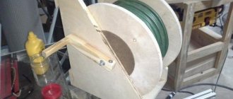
Layout of the power unit and transmission of the walk-behind tractor:
1 - engine; 2 — output sprocket of the secondary shaft of the engine gearbox; 3 - chain (t=15.875); 4 — motor mount; 5 - gearbox; 6 — drive sprocket of the gearbox; 7 — gearbox drive shaft (steel, circle Ø35); 8 — gearbox trim (angle 30×30, 2 pcs.); 9 — tension mechanism bar (steel, sheet s4); 10 — tensioning mechanism sprocket; 11 — front engine mounting bracket; 12 — rear engine mounting bracket; 13 — pulley attachment for forced air cooling of the engine
Gear shaft
Secondary gearbox shaft (drive shaft of wheels and cutters)
Industrial cultivator cutter for a homemade walk-behind tractor
Pulley attachment (on the generator armature) of the forced air cooling system:
1 — pulley attachment (steel, Ø 63); 2 - generator; 3 - M7 bolt securing the pulley attachment to the generator armature
Then I moved on to the layout of the relative position of the power unit and gearbox. But I first made a motor mount (in fact, it also serves as the frame of the entire walk-behind tractor). The motor frame is a square pipe 600 mm long, welded from two sections of channel No. 12. The power unit crankcase was placed on top of the motor mount, and the gearbox housing was attached to it from below so that the drive shaft was located approximately in the middle of its length. Since the distances from the symmetry planes of the motor and gearbox are different, the first had to be shifted ten millimeters to the left (along the direction) side. At the same time, the engine crankcase was moved further forward on the engine mount in order to slightly increase the distance between the transmission sprockets and install another one between them - a tensioner. In this place of the transmission (between the sprockets of the power unit and the gearbox), an intermediate shaft (sometimes called a “speed reducer”) could be installed to increase traction. But on my walk-behind tractor, the acceptable overall gear ratio is “derived” due to the use of a gearbox from IZH-56, and the engine power is already in excess.
After checking the relative position in one plane of the output sprocket of the power unit (the sprocket of the secondary shaft of the gearbox of the power unit) and the input sprocket of the gearbox, I welded the trim of the crankcase halves to the engine mount, and for mounting on the engine mount of the power unit - brackets made of 4-mm steel sheet, curved in in the form of a stamped channel. I installed the engine crankcase on the engine mount, tried it on and welded the brackets to it. I drilled mounting holes in the brackets locally. In fact, if you make oblong grooves in the engine crankcase mounting brackets instead of ordinary holes, you can do without a tension sprocket, and tension the chain by shifting the engine relative to the engine mount, thereby simplifying the design of the transmission.
After assembling the main units, I began to design the remaining fasteners: control levers, towed and mounted devices. The control levers (made of thick-walled pipe with an outer diameter of 27 mm) are screwed to the rear mounting bracket of the power unit and supported by struts. And on the levers themselves, I later attached the fuel tank to the racks. At the rear, a towbar was welded to the engine mount - part of the towing device of the walk-behind tractor with the trolley. The forklift is used for attaching land-cultivating implements: plows, cultivators, etc. A pin was welded to the motor mount in front for attaching ballast plates, which increase traction on a muddy country road or with the soil when cultivating plantings on the site.
As noted at the beginning of the article, the engine cylinder was equipped with forced air cooling. The centrifugal impeller comes from the interior heater of a UAZ car. The impeller drive is via a belt drive with pulleys with a gear ratio of 1. The drive pulley is mounted on the generator rotor. A rubber ring (“pass”), cut from the camera of the IZH motorcycle, is used as a belt - it does not require tension and can be easily removed to turn off the drive in cool weather. The casing was glued from fiberglass with an epoxy binder over a pre-fabricated wire frame. It (the casing) is quick-detachable and is secured to the cylinder with two springs. But it must be admitted that the impeller does not fully provide cylinder cooling in extreme conditions when driving in low gears, and therefore I plan to replace it.
I also didn’t make the cutters (there are two of them), but, like the wheels, I bought them, or, in other words, “crow’s feet” - they are made at the local Perm plant for the Cascade walk-behind tractor. The milling cutter hubs - thick-walled pipes with an internal diameter of 30 mm - fit onto the shaft of my walk-behind tractor without modifications - after all, I machined the shaft for them. The cutters are secured to the shaft with two bolts each, through the corresponding through holes in both parts. The sweeping diameter of the cutters along the “arrows” is 350 mm. Each is equipped with four rows of paws (three paws per row). And it should be noted that I was pleased with these cutters: they do not crush the weeds, but throw them to the surface (although sometimes they get wound up), do not bury themselves in the ground and move smoothly. I even conducted the following experiment: I let a working walk-behind tractor “free float” along a 50-meter area, and it plowed (cultivated) normally on its own, without turning anywhere. The designs of similar, but home-made cutters have been presented more than once on the pages of the “Modelist-Konstruktor” magazine, and therefore I give only photographs of them, without drawings. The working width when cultivating with shaft extensions is up to 900 mm.
In addition to the “pointed” cutters, he adapted ready-made or manufactured other land-cultivating tools: a plow, a hiller, a cultivator, a potato digger.
The minimum speed of the walk-behind tractor is about 5 km/h. At this speed I plow, cultivate, dig potatoes.
I installed an electronic ignition on the engine - from the Voskhod motorcycle. The walk-behind tractor is equipped with a traveling headlight.
Since the walk-behind tractor was immediately conceived as a motor-tractor, I made a trailed single-axle cargo trolley for it with a body with a lifting capacity of up to half a ton and a double seat. Making a soft sofa with a back was also not difficult, but then it would be impossible to transport long loads, and sometimes you have to transport logs up to six meters long. However, it is not difficult to make the back removable. The trailer drawbar is made of a rectangular pipe with a cross-section of 50×40 mm with 2.5 mm walls. It is supported by two more struts from equal-flange angle No. 4.
The towing device is simple but reliable, of the pin type. The body of the cart with plan dimensions of 1200×1200 mm is made of wood, the sides are made of 16 mm thick lining boards, the floor is made of twenty boards and lined with 1.5 mm steel sheet.
Walk-behind tractor with hiller made from disc cultivator cutters
Trailed single-axle cargo trolley:
1 — towing device; 2 — drawbar (steel pipe 50×40); 3 — drawbar beam (steel angle 40×40.2 pcs.); 4 — trunk (steel sheet s1.5); 5 — body (lining board s16); 6 — wheel fender (from the IZH-56 motorcycle); 7 — body frame (from the IZH-56 motorcycle); 8 — trolley wheel (from the IZH-56 motorcycle); 9 — seat-trunk lid (board s20); 10 - floor (board s20); 11 — body floor (steel sheet s1)
Trolley coupling unit:
1 — pivot bushing (pipe Ø50×30); 2 — overlay (steel sheet s4, 2 pcs.); 3 — swivel (steel, circle Ø45); 4 — swivel bushing (pipe Ø50×30); 5 — drawbar beam; 6 - drawbar
A very important component of a walk-behind tractor trailer is the coupling device. Its design may be different, but reliability must be ensured. It should also allow the trailer to rotate relative to the walk-behind tractor not only in the horizontal plane, but also in a limited vertical sector, so that the cart wheel does not freeze. The photographs show device options
Even impassable places are not an obstacle for the “tandem” of a walk-behind tractor and a trolley
A walk-behind tractor in a transport version with a single-axle cargo trailer made on the chassis of two side trailers of the IZH-56 motorcycle
The chassis of the trolley with a wheel track of 1500 mm is assembled from two side trailers from the IZH motorcycle. The wheels are also from him. Their suspension is torsion bar and soft, so driving a walk-behind tractor-trolley tandem 60-70 km on a relatively flat field road is not difficult. Up to a speed of 50 km/h, the tandem is easy to control. During the season I drive 3-4 thousand kilometers on it on business: to the forest for firewood, to the field for hay (I just haven’t “taught” how to mow it yet) and fishing. A very important component of the trailer and walk-behind tractor is the towing device. Its design may be different, but reliable. It should also allow the trailer to rotate relative to the walk-behind tractor not only in the horizontal plane, but also in a limited vertical sector, so that the cart wheel does not freeze. The total length of the trailed trolley is 2.5 meters.
Due to the engine power, interlocking wheels shod with tires with a large herringbone tread, and speed qualities, the walk-behind tractor with a trailed trolley turned out to be an all-terrain vehicle, so I use it from early spring to late autumn. In some road (or rather, off-road) situations, the reverse gear that appeared due to the gearbox also helps out. The wheels on the shaft, or rather their hubs, are secured with two bolts. But due to the merciless use of the walk-behind tractor, the bolts were cut off more than once. Therefore, I additionally secured them from turning on the shaft with longitudinal cylindrical keys.
The walk-behind tractor has become an indispensable assistant in the garden and in general on the farm.
During operation, I only rebuilt the gearbox: the play in the bearings increased. And I regretted it - I could still go for two seasons.
R. AKHMETZYANOV, p. Siva, Perm region
We recommend reading
- WHAT BRAND OF CEMENT? The quality of cement is usually determined by destroying samples. Moreover, this process lasts from seven to twenty-eight days. Young technicians from the radio engineering circle decided to speed it up...
- FLYING OVER THE WATER Today we offer unusual material to the attention of ship modellers. If most publications were based on existing developments and were devoted to already implemented results...
Here you can evaluate the author's work:
How to disassemble?
The gearbox itself is removed from the Ant in a certain sequence. It needs to be disassembled if its operating functions are no longer satisfactory during operation. Sometimes it happens that when it breaks, it is sent to a landfill. But this is fundamentally wrong. This device can almost always be repaired, and it will continue to function and serve for quite a long period. Also, the “Ant” scooter is currently a rarity, and spare parts for it are extremely difficult to find. Therefore, there is no need to “throw away” them in vain.
The device itself is dismantled and mounted on a scooter quite simply, there are almost no problems.
Disassembling the gearbox will also not bring unnecessary trouble. But assembly will also require increased attention; you need to carefully assemble everything, not miss anything or confuse anything. Gears are made of high strength steel (alloy steel), so they very rarely become unusable or deformed. The main problem in most cases lies in the bearings. Therefore, regular and careful attention to these parts is required, in particular to elements such as oil seals.
How to disassemble the gearbox
The Ant gearbox is disassembled according to a certain scheme. This process is necessary if for some reason Ant’s gearbox stops functioning. Some people do it wrong: when the gearbox breaks, they simply throw it away. But with the right approach to this matter, the device can be repaired, after which the Ant scooter will function the same as before. In addition, it is difficult to buy spare parts for the Ant scooter, so you shouldn’t waste them.
Motor scooter gearbox Ant
- If the Ant gearbox has been disassembled for some time, then first it would be a good idea to clean it of dust and dirt.
- Unscrew all the bolts that secure the gearbox. Take a hair dryer. Use it to warm up the Ant gearbox from all sides, then tap the housing with a wooden mallet. Until it splits into two halves.
- Now you can find out what caused the breakdown. The gearbox could fail for two main reasons: the input shaft bearing was broken or the gear teeth were worn out. Both parts will have to be replaced.
- Gears and bearings need to be removed so they can be replaced with new parts.
- Remove the retaining shield.
- Remove the retaining ring and remove the axle shaft from the cup.
- Before you start putting all the parts back together, you need to check their integrity. When the Ant gearbox is assembled, it can be sent to its designated location.
The Ant scooter can become a useful type of equipment today. If you have your own farm or garden at your dacha, you won’t find anything better than such a scooter.
Motor scooter repair Ant
Before starting repairs, you need to buy all the necessary spare parts and tools. Of course, you first need to diagnose the device in order to understand what the real problem is.
It is also necessary to take into account a few tips on how to change certain spare parts:
Repair is accompanied by the following basic actions:
Typically the engine will stop running if these parts become too dirty. Here you may need new spare parts - oil seal or bearing. Replacing them is quite simple. Sometimes spare parts are not needed: you just need to clean the mechanism of dirt.
But at this stage, many people who have an Ant scooter, but who are not familiar with how to properly repair it, make the same mistake. It consists of the following: they close the oil channel with a gasket or lubricate it with sealant. But this is wrong, since this closes the paths through which the lubricant passes to the oil seal and bearings. This leads to parts breaking, which is why new parts may be needed later. They are quite rare to find on sale. But you can buy spare parts in some online stores, but no one knows what their quality will be.
Photo report Conversion of Ant scooter on magneto
What is a truck traffic law? What is a truck, traffic rules. Maximum speed, parking restrictions and other traffic rules innovations
I just finished overhauling the Ant engine and decided to write a short report on installing a magneto. Of course, the engine had to be half charged with spare parts made by no one. I suspect that the counterfeit goods with which I had to tinker for the last two days are being produced in some garage in Rostov-on-Don, or that the local workers are secretly making this nonsense at the factory. In any case, according to my information, traders bring this disgusting stuff from Rostov.
The engine to which I have devoted the last two days has already been converted to a magneto. Plus, there was another “Ant” in my yard, also converted by someone to use a magneto, but the store spacer to which the magneto is attached was “pinned” from it at one time... I had to buy a new spacer and the owner at the same time bought a coupling . I don’t know why he bought it - I didn’t ask him for it. The old one was in good condition. Well, since I bought it, we’ll install it.
The feasibility of installing a magneto
It’s none of my business, of course, but I have an extremely negative attitude towards this kind of collective farm tuning. Moreover, the magneto does not solve the problem with the reliability of the standard ignition system, but only replaces it with another problem. And this, in my opinion, is complete stupidity: convert the engine to a magneto, and then suffer even more with it...
Yes, the dyno starter is not an ideal device. Which also needs to be constantly monitored and, if necessary, serviced. So what? Well, I cleaned the collector and breaker contacts at the beginning of the season and that’s it. Are there fewer problems with the magneto? More than a hundred times!
- Firstly, due to the fact that the rubber coupling constantly breaks, the ignition timing is lost, and this entails detonation, loss of power, overheating and increased fuel consumption.
- Secondly, after installing the magneto, they usually stop monitoring the dyno starter, deprive it of its battery, and it eventually dies completely... Accordingly, the on-board network of the scooter is deprived of its power source. And this means that “there is no light - there will be no cinema”...
- Thirdly, due to the fact that this whole alteration is a complete collective farm - the axes in which the magneto rotor and the dynostarter rotate diverge within significant limits. And this leads to the fact that the parts of these two devices begin to work with a large axial misalignment relative to each other, which is why the magneto’s output shaft of the rotor constantly breaks off and its support bearings fall apart.
- Fourthly, the magneto was not initially designed for long-term operation, much less to work with such a horse-like misalignment along the axes, which leads to an increased radial load on the rotor, which is not typical for a magneto.
- Fourthly, a magneto is very expensive - plus you need to buy a spacer and a coupling.
We buy a spacer at the nearest store (it costs 450 rubles), a coupling (100 rubles) and a magneto (used from 1500 and above...).
Installation
We screw the coupling to the dynostarter rotor directly on top of the fan. The option of fastening the coupling with bolts in a hidden way, in my opinion, looks more preferable.
Than the option with regular bolts.
We break out the protective grille from the cooling volute.
Using a round file, we align the snail from the inside so that the spacer fits into it. We insert the spacer into the volute, mark the holes along the spacer mounting eyes. We drill holes and cut M6 threads into them, the main step.
We install the magneto and voila!
How not to make a mistake when choosing a gearbox?
When choosing this device, it is worth considering the work it will perform. Both its reliability and performance, as well as its operational period, will depend on this. If you make a mistake when choosing a device, you can “kill” the gearbox ahead of time. It is advisable to entrust the choice to qualified specialists. They will make all the calculations and advise you on the best option for the task at hand.
But there is not always a chance to get advice from an experienced specialist. In this case, you need to take the initiative into your own hands. The first step is to create the kinematics of the drive. It will tell you what type of gearbox is required for the selected system.
To determine the subordinate number, use the formula:
In this formula, ninput means the number of revolutions that the input shaft has, that is, it shows the engine speed in 1 minute. The noutput parameter means the required number of revolutions that the output shaft needs (also revolutions per minute).
Having made the calculations, the resulting transmission value will need to be compared with the values of the standard series for all types of gearbox. It is important not to forget that the resulting calculation is not exact, it is only approximate. When choosing an electric motor whose shaft rotates at a frequency not exceeding 1500 revolutions per minute, you should take into account the technical characteristics of the electric motor or mechanism itself, and then carry out an analysis and carefully select.
Stages of assembling an ATV
To create a homemade ATV with your own hands, you need to go through 9 stages of work step by step:
- Acquisition and preparation of everything necessary;
- Welding (alteration) of the frame;
- Installation of suspensions, brakes, chassis, shock absorbers, wheels;
- Installation of engine, gearbox, drive assembly;
- Installation of the fuel system;
- Installation of electrical equipment - turn signals, headlights, dashboard, battery;
- Case manufacturing;
- Priming, sanding and painting the body, (if desired) sophisticated custom tuning;
- Installation of the body and seat.
After the final stage, the finished miracle of home-made equipment will need to be thoroughly tested, gradually making road (and off-road) conditions more difficult.
Spare parts price
Despite the fact that the production of the device stopped long ago, you can still find new spare parts for it that are produced by the industry. Some parts are imported, some come assembled. Supplied in sets:
The necessary parts can be found on the Internet using store catalogs. Prices for spare parts for the Ant scooter are fair. Here are some examples:
Judging by the prices, the device is more than cheap to repair. This is an important operational property for people in rural areas.
In terms of tuning the Soviet Ant vehicle, the owners can’t think of anything. After all, these are often tech-savvy people who like to spend time in the garage. Several directions can be distinguished:
The main task when tuning is to increase reliability and less tinkering with details due to breakdowns.
In terms of engine tuning, some owners took radical measures and installed a Lifan engine (Lifan 188f), which has a volume of 400 cubic meters, on the Ant scooter. cm. And its power is 13 hp. A distinctive feature of this assembly is the variator and centrifugal clutch.
A centrifugal clutch is not the best option for trucks, since when driving on rough terrain on a loaded scooter at low speeds, it may slip. And this incapacitates him.