Homemade ekranoplan
According to the definition formulated in the “Interim Guidelines for the Safety of WIG-Grounds” adopted by the IMO: an ekranoplan is a multi-mode vessel that, in its main operational mode, flies using the “screen effect” over water or other surface, without constant contact with it, and is maintained in air, mainly by the aerodynamic lift force generated on the air wing (wings), body, or parts thereof, which are designed to use the action of the “screen effect”.
The main goal that we have set for ourselves is to create a rescue device that can quickly provide assistance drowning or people in distress on the water and, with minimal loss of time, deliver the victims to the shore for emergency assistance. Of course, such a device can also be used for communication. It seemed to us that with the help of a simple hinged wing device it was possible to give completely new qualities to almost any vessel mass-produced by our industry - be it a motorboat or a speedboat.
To begin with, we chose as a basis the hull of a fiberglass motorboat with trimaran contours, known as “Crystal” (this boat was produced in a small series by OSVOD enterprises). Easily removable planes of an arrow-shaped (in plan) shape were installed on it, having a large negative V and a trailing edge immersed in water (the general view is shown in Figure 1, a diagram in three projections is in Figure 2). At the same time, the boat itself has not undergone any serious modifications, except for strengthening the transom and gluing in bosses for attaching the motor mount.
During the testing process, we intended to test two propulsion options - first a water propeller and then an air propeller, driven in both cases by the power head of the Whirlwind-25 outboard motor. In the first case, control is carried out by turning the entire motor, in the second - using an air rudder with an area of 1.2 m2, located directly behind the propeller.
As mentioned above, at high speeds, many motorized vessels tend to take off from the water and enter flight mode at a very low altitude, usually determined by the depth of the propeller (if a propeller is installed, this height can be much greater). Very often, ships with water propellers, jumping out of the water, continue to move without touching the water at all, as experts say - “on one propeller.”
But such a movement is practically uncontrollable and even dangerous. The wing system we developed, thanks to its special shape, makes flight near the surface of the water more stable and, most importantly, self-regulating: when a roll occurs on the wing going down, the lift force quickly increases, and straight flight is restored by itself. As a result of such self-regulation, there is no need to install aircraft-type ailerons, and control of such a vessel does not require long training for the driver.
The flight itself (if a conventional outboard motor is installed) occurs as follows: in a static position, with a normal draft of the boat, the trailing edge of both planes is immersed in water to a depth of 80-100 mm; when starting from a stop and at speeds of about 20-30 km/h, these submerged sections of the wings create additional hydrodynamic lifting force, facilitating the “floating” of the boat; at the same time, an aerodynamic lift force arises on the unsubmerged part of the wings, and when the boat reaches an air speed of about 50-55 km/h, the wing system is separated from the water surface. The narrow gap that forms between the trailing edges of the wings and the water facilitates the oncoming flow of the boat along the hull, thereby increasing the lifting force and, as it were, “smoothing out” waves and spray jets. The boat takes off and continues to move at a height of 0.3-0.5 m, using the effect of a dynamic air cushion.
From the above, it is clear that the most advantageous way for a quick takeoff is to move against the wind - in this case, its speed is summed up with the speed of the boat, and the required air speed is achieved faster. If an outboard motor is installed, the flight altitude is adjusted automatically; As the propeller emerges from the water, it may decrease as the propeller thrust decreases. This interdependence makes it easier to control the device and allows us to hope for widespread use of “flying boats” with outboard motors in the near future.
A propeller-driven installation with a propeller significantly expands the scope of application of “flying boats”, since they become independent of water and are able to continue flying over almost any underlying surface, be it sand, wet meadows, moth areas of reservoirs or ice. In this case, the flight altitude can increase (with the described wing device) to 1-1.5 m.
The propeller-motor installation developed and built by us consists of the power head of an outboard boat motor “Vikhr-25” with a chain drive to the propeller. The reduction is 1:3, which allows maximum use of the propeller efficiency. Since the Whirlwind engine is water-cooled, it had to be equipped with a water radiator and an expansion tank with a capacity of 2 liters. As a water radiator, you can use an oil cooler from a Moskvich-412 car or one of the available car water heaters, installing it so that it is blown by the air flow from the propeller.
Young technician - for skilled hands 1980-01, page 4
SNOW SANDALETS. Two designs of sandals (Fig. 13, 14), worn directly on ski boots, were invented by the Americans K. Herold and D. MacDonald. You can make yourself a particular pair of sandals of your choice in a few hours.
Select a smooth 30mm thick birch board and some leather straps. Stand on the board with your right boot so that the grain of the wood runs along the boot. Outline its outline with a pencil. Do the same for the left shoe. Allow an allowance of 15-20 mm along the contours on the left and right, and 30-40 mm on the front and back.
Straighten the outline along the long sides. Cut the workpieces with a hacksaw. Use a knife to carefully trim the bottom
flat, giving it a slight convexity in the middle. Make grooves on the side surface. Use furniture nails to nail the backs and straps into the grooves. Herold's sandal remains firmly on the sliding surface
twist low blades. Thanks to them, it will be easier to make turns. McDonald's sandals have a more false back design and closed-front toes.
V. ZAVOROTOV Fig. V. MOTHERLAND
ESKA-1 is an amphibious ground-effect rescue boat created by a group of Young Specialists at the Central Laboratory of New Types of Rescue Equipment.
ESIA is a hovercraft, but a special one. Typically, boats of this type are equipped with fans, which create an air cushion. In an ekranojet, it occurs due to the oncoming air flow: excess pressure is formed between the wing and the screen (surface). It creates lift under the wing of the device.
Ekrgnolet can quickly glide along the water surface of a lake or reservoir, easily take off from the water and fly at a meter altitude.
The ekranolet is equipped with a 30-horsepower motorcycle engine and can reach speeds of up to 120 km/h.
We talked in detail about the ESKA-1 ground effect vehicle in UT No. 2, 1974.
So, we suggest you make a model of an ekranopet.
Drawings of the model are made on a scale of 1: 33 from natural size.
To work, Eam will need: drawing paper, thick cardboard, several paper clips, pieces of cork and transparent film. Conventional tools: knife or scalpel, scissors, awl.
The model consists of a cardboard frame, the parts of which are marked with letters, a paper covering - its parts are numbered in Arabic numerals, and wire parts - they are marked with Roman numerals.
FRAME. First of all, make the cardboard parts of the hull frame: B, C and frames A, D, D, E, R, C. You need to copy and cut out these parts very carefully - then they will fit each other exactly. Using the assembly diagram, glue the body frame. In the place indicated by the arrow, glue the cabin 19 with the seat 18 and the control handle V (its base is wrapped in paper tape 17 with glue). Glue pieces of cork on both sides of part B.
Now you can start gluing the body frame with paper parts. First of all, glue the skins 9 and 16. Glue the bottom parts 14 and 15 from below, and part 2 from above.
We recommend cutting out the parts of the cockpit canopy Z1 and 41 from transparent film. Then the interior design of the cabin will be visible - this will decorate the model and give it an even greater resemblance to a real ekranolet.
According to the fold lines indicated in the drawing, bend part 41 and insert it into the gaps between the cabin 19 and the casing 16. Glue part 4 on top. Then glue part 3 onto part Z1. Secure the resulting windshield with glue in the space allocated for it.
KEEL. Its power part - the frame - is already ready, and all you have to do is glue the casing 10 in place.
The STABILIZER is glued together from paper part 11, inside of which cardboard is preliminarily inserted -*
on
A
Assembly instructions for the Kasatka-1 ekranoplan
oflin
Full Member
The two-seat ekranoplan Kasatka-1 is intended for active recreation, piloting training, and can also be used for other purposes. The ekranoplan was designed according to the “semi-tandem” design, which made it possible to significantly reduce the dimensions of the structure. The well-known disadvantage of the tandem wing arrangement, shadowing of the rear wing, is eliminated by bringing the wings closer together to the point where a slot effect begins to appear.
1. License agreement 2. Description of the Kasatka-1 ekranoplan 2.1. Purpose 2.2. Main dimensions 2.3. Flight performance 2.4. Aerodynamic layout 2.5. Hydrodynamic layout 2.6. Management 2.7. Materials and components 3. Assembly of the ekranoplan 3.1. Bottom 3.2. Fuselage strength set 3.2.1. Drawings and assembly of frames 3.2.2. Longitudinal frame of the fuselage 3.2.3. Additional fuselage elements 3.3. Fuselage skin 3.4. Keel 3.5. Glazing 3.6. Wings 3.7. Management 4. WIG testing 5. Applications
Attachments
Yakut-AZ1
Living in the sky.
oflin
Full Member
oflin
Full Member
Dimensions (length, width, height) 5.5x5.5x2 m Cabin (length, width, height) 2.0x0.75x1.2 m Transport width 2.0 m Draft 0.2 m Capacity 2 people Fuselage Frame, glass-basalt-plastic , extended Fiberglass wings, with extension 4 and 8 Load-bearing area 10 sq. m Specific load per area 40-55 kg/sq. m Fuel system Tank with a capacity of 40-50 l Rotax engine, 65 or 80 hp 3-bladed propeller, adjustable pitch, D 1600 mm Static thrust 140-180 kg Ekranoplan empty weight 300-350 kg (up to 200 kg fuselage, 60 kg SU, 50 kg wings) Load capacity 200 kg Payload 33-40% Max. movement speed on the screen (ice/water/snow/sand) >200/170/200/200 km/h Cruising speed on the screen 150/140/140/140 km/h Lift-off speed 65-70 km/h Lift-off distance 50- 100 m Aerodynamic quality Up to 25 screen, up to 12 aircraft mode Fuel consumption 10-15 l/h Range 500 km Optimal flight altitude 0.5 m
oflin
Full Member
oflin
Full Member
Thus, to longitudinally stabilize the ekranoplan, four factors are used simultaneously. Let's consider the operation of the aerodynamic system in some modes:
A. As a result of a gust of wind, the ekranoplan began to lift its nose. To stop pitching, it is necessary that the lift force on the rear wing grows faster than on the front wing, which occurs due to: 1. A slight relative increase in the angle of attack of the main part of the rear wing. 2. Significantly increasing the angle of attack of the cantilever part of the rear wing. 3. A sharper dependence of the lift coefficient on the angle of attack at the rear wing. 4. Increasing the intensity of the vortex rope behind the front wing, as a result of which the flow of air through the ends of the rear wings is reduced.
B. From a gust of oncoming wind, the ekranoplan began to leave the screen.
1. The lift on the front wing is reduced because the ground effect is weakened. 2. The intensity of the vortex rope behind the front wing increases, which leads to an increase in lift on the rear wing. 3. The speed of the air flow increases, and with increasing speed, the lift force on the rear wing increases faster. As a result, the ekranoplan will have a diving moment, which will return the ship to the screen.
B. The ekranoplan descends from airplane mode onto the screen.
1. The lift on the front wing increases due to the ground effect. 2. Due to the screen effect, the intensity of the vortex rope behind the front wing decreases, which leads to a decrease in the lift force on the rear wing. 3. Flight speed decreases, causing lift on the rear wing to quickly drop. As a result, the ekranoplan raises its nose until the increase in the angle of attack and the increasing tip vortices behind the front wing increase the lift force on the rear wing until the pitching moment of the system is fully compensated. The stabilization angle depends on the speed of the ekranoplane; the lower the speed, the more the ekranoplane will lift its nose, trying to maintain altitude.
oflin
Full Member
The first runs and takeoffs are best done in winter, on snow, at an air temperature no higher than -5 degrees. If it is warmer, the snow becomes sticky, the ekranoplan picks up speed more slowly, but in general this is not a big hindrance. Assistants must be present during the tests. Assistants must immediately be taught two simple rules: 1. Never enter the plane of rotation of the propeller 2. At the pilot’s command: “Away from the propeller,” you must quickly move away from the ekranoplan and not approach until the engine stops. People often do not understand the importance of these rules; there have been cases when, after starting the engine, someone rushed to lift or correct something, and ended up getting injured. Having given the command, the pilot must look around, and only after making sure that the command has been completed, turn on the starter. The pilot needs to feel the ekranoplan, for which he runs at a speed of no more than 40 km/h. Jogging should be done until the legs begin to press on the pedals themselves, without the participation of the head. That is, the action needs to be worked out until it becomes automatic. While jogging, you don’t have to cling to the rear wings; the front wings are enough, the function of which is to prevent the ekranoplan from turning over during excessively sharp turns. The pilot’s task at the first stage is to learn to keep the ekranoplan in a straight line. Then the rear wings cling and the running speed increases to 60 km/h. Now we need to learn how to work in the gas sector. The lever must be moved smoothly, never reducing the speed abruptly. Loss of speed at low speed is equivalent to loss of directional control, since the rudders work in the propeller flow. You should not reduce the speed below 30%. If the ekranoplan begins to skid, you need to add speed and counter the beginning skid with the pedals. When the ekranoplan reaches a speed of about 60 km/h and the speed is reduced, the torque from the propeller that presses the nose during takeoff decreases. The ekranoplan “swells up” and flies several tens of meters at a centimeter height. That is, these are already approaches. You need to feel them well before picking up speed over 70 km/h. Using the pitch stick, achieve the maximum length of the approaches. Then take the handle “on yourself” and look at the behavior of the ekranoplan. If the ekranoplan raises its nose too sharply, the center of mass should be moved forward. If the ekranoplan does not swell, move the center of mass towards the stern. Moving the center of mass can be done by reversing the battery or adding small weights in the nose or tail. At a speed of about 70 km/h, the ekranoplan will switch to flight mode on a low screen - 10-20 cm above the surface. Here you need to prevent the ekranoplan from accelerating more than 80-90 km/h. Slowly reduce the speed and get used to the screen. It's time to carefully work the handle along the roll. Don't be afraid of getting caught in the wing; the air cushion won't let you. Giving the handle left and right, feel the work of the elevons. The ekranoplan will follow the handle, moving sideways in the chosen direction. When releasing the gas, remember the torque from the propeller. The ekranoplan will raise its nose, and the pilot is obliged to extinguish the tendency in time. You should not let the ekranoplan raise its nose more than 10 degrees, and if you are late, get ready to be “caught.” The front wing begins to rapidly increase lift after an angle of attack of 20 degrees. Don't forget that the wing mounting angle is 10 degrees. At low speeds, the rear wing works less efficiently, so it will dampen the pitch-up at an angle of 40 degrees. You must push the stick completely away from you and watch the roll. The ekranoplan will slow down, lower its nose and land. After mastering low speeds and clarifying the alignment, you can accelerate the ekranoplan more strongly, but gradually. Add 10 km/h and look at the trends. 120-130 km/h is your limit until you have flown at least 50 hours and feel the device thoroughly. An airplane pilot makes a mistake once, an ekranoplane pilot makes a mistake half a time, after which he again becomes an ekranoplane builder.
The simplest do-it-yourself ekranolet
“Flying saucer” - do it yourself
Discolet? Anti-gravity? Whirlwind!
TM No. 5 for 1990 mentions an excerpt from a Sanskrit manuscript (“Samarangana Sutradhara”) containing a description of an aircraft - a “vimana”, which, according to some researchers, is nothing more than an “alien ship”. In this case, the “drawing” and “specification” recorded in ancient sources is another confirmation of paleocontact of the 3rd kind. But how close is all this to reality? In order for the further course of our reasoning to be clear, let us again read the description of the “vimana”:
“His body, made of light material, should be strong and durable, like a large flying bird. A device containing mercury and an iron heating device underneath should be placed inside. By means of the power which lies hidden in mercury and which sets in motion the carrying vortex, a person inside this chariot can fly long distances across the sky in a most amazing manner. Four strong containers for mercury should be placed inside. When they are heated by controlled fire from iron devices, the chariot will develop the power of thunder thanks to the mercury. And she immediately turns into a “pearl in the sky.”
So, “device with mercury”, “heating device”, “carrying vortex”. – what would that mean?
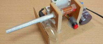
To begin with, let us recall that a heated vessel with mercury is the basis of the simplest diffusion vacuum pump (DVP). Is it not with his help that the ancients offer us to rise into the air?
Of the various pump designs, I settled on one that resembles this description - a toroidal type. Externally, it is a flat cylinder filled with liquid metal - mercury. Below it is a microwave oven (“heating device”) and electromagnetic coils—the stator. The latter creates a “running” magnetic field, causing the mercury to rotate, which becomes like the rotor of an asynchronous motor. Its rotation speed is several hundred thousand revolutions per minute. Under the influence of centrifugal force, mercury will take the shape of a donut-toroid, in which, due to uneven heating, an internal vortex motion also occurs (a spiral laid in a donut). Thanks to the “heating device”, mercury will go from a liquid to a state of supersaturated vapor.
Due to the rotation of the “steam donut” and the diffusion of specially supplied air into it, a very high vacuum is formed in the cylinder. Due to internal vortices in the “rotor”, the absorbed air ends up at its periphery and is squeezed towards the inner wall. Next, it is collected by a special jacket and thrown out through a jet nozzle. But this flow pushes the device forward, and something else lifts it off the ground.
Air enters the DVN from above. It rushes towards the air intake opening, and not in a straight line, but twisting in a spiral. Above the upper skin of the device, around the hole, its rotation speed will exceed 500 km/h, which will lead to a sharp drop in pressure and the formation of a vacuum zone. This, according to Bernoulli’s well-known law, means the emergence of a huge lifting force (“carrying vortex”), comparable to the force of a tornado.
In addition to the impressive lifting force and simplicity of design, toroidal-type DVNs (or, as I called them, “Tornado” DVNs) have at least two more valuable properties. Firstly, they have a significant gyroscopic effect. This is very important, because at high speeds diskettes have little stability. The arrangement of four gyroscope turbines will increase stability many times over. The second required quality is the ability of the pump to levitate due to the monstrous rotation speed of the mercury rotor. At the same time, its weight is compensated.
Let's return to the drawing in the Sanskrit manuscript. Obviously, a cross-section of the aircraft is shown. We see two DVN turbines with 4 pumps each. From an engineering point of view, the coaxial arrangement of pumps with a common air intake is optimal for increasing engine power for a given donut diameter.