Homemade deep blue delay pedal for electric guitar
Since ancient times, guitarists have been interested in one question: “how can you diversify your sound and make it unique?” This is why a variety of effects pedals come to the rescue. Today we’ll talk about how to make the famous deep blue delay pedal.
It all started with the fact that I felt a strong need for some kind of pedal, other than the already existing overload. After much thought, I came to the conclusion that the basis of every modern guitarist’s pedalboard are two pedals: distortion and delay. I decided to choose the most popular delay pedal at that time, but since it is quite expensive in stores (especially the hand-assembled model), I decided that I needed to take this matter into my own hands.
Let's start with what this pedal is.
Delay (from English Delay - delay) is the effect of delaying sound, implemented by adding a copy or several copies of it, delayed in time, to the original signal. The delayed signal can be played either once or several times. The delay time is usually at least 50-60 ms.
Now I'll show you how to make it
First, you need to get hold of all the elements necessary for assembly:
- Fiberglass
- More wires
- 3PDT button
- Jack 6.3 (mono) sockets – 2 pcs.
- Power supply socket – 1 pc.
- Potentiometers B50k – 3 pcs.
- Housing Gainta g0124
- Handles for potentiometers – 3 pcs.
- LED blue
- Diode 1n4007 – 1 pc.
Resistors (0.125 W):
- 1M – 1 piece
- 360K – 1 piece
- 180K – 1 piece
- 100K – 1 piece
- 22K – 1 piece
- 20K – 2 pcs.
- 12K – 1 piece
- 10K – 7pcs
- 5.1K – 1 piece
- 2.7K – 1 piece
- 2K – 1 piece
- 1K – 2pcs
- 33 – 1 piece
Capacitors (voltage not lower than 16V):
- 100uF 16V(electrolyte) – 1 piece
- 47uF 16V(electrolyte) – 3pcs
- 1uF 16V (electrolyte) – 4 pcs.
- 100nF – 4pcs
- 47nF – 1 piece
- 22nF – 2 pcs
- 15nF – 1 piece
- 10nF – 1 piece
- 4.7nF – 1 piece
- 2.2nF – 2pcs
- 100pF – 1 piece
- 47pF – 1 piece
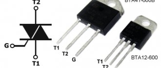
Chips:
- TL072
- PT2399
- 78l05
It is worth mentioning such a phenomenon as an earth loop: “an earth loop is the unevenness of the grounds, in other words, different potentials at the grounding points of the power cables of two or more devices (blocks inside the device), sometimes grounded screens. Well, where the potential difference is, there is, respectively, voltage and current (parasitic), the appearance of which is expressed in noise and constant interference.”
To avoid the appearance of ground loops, and with them various unnecessary interference, it is necessary to ensure that all the disadvantages of the circuit are reduced to exactly one point and contact the body only at this point. The body of one of the potentiometers will act as this common point.
The scheme also provides true bypass. Actually, this is a switching method in a pedal in which, when turned off, the signal goes directly from input to output, bypassing the lotion circuit itself.
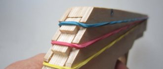
The next stage of assembly is the manufacture of the printed circuit board. In this option, you need to make two different boards.
Manufacturing stages:
- First you need to cut out the required shapes of PCB pieces
- Next you need to clean them with sandpaper to remove patina and better tinning.
- Print tracks on thermal transfer paper
- Place the printout on the PCB and iron it with an iron at maximum power for several minutes until the design is transferred from the paper to the PCB
- Wait until it cools completely and then separate the paper from the PCB. If there are unprinted areas, then you need to paint them yourself with nail polish or any other
- Prepare an etching solution (a tablespoon of citric acid, a teaspoon of salt per bottle of hydrogen peroxide), etch the board, and wash off the toner.
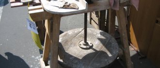
- Drill holes for elements and wires and tin the tracks
When drilling the body, it is better to first mark all the holes, applying the markings to the body. This is all that is needed to make a good board, but due to inexperience, of course, there will be inevitable mistakes.
The input capacitor is a film capacitor - 22 nF, which can be increased a couple of times, the low frequencies will increase.
In order to avoid short circuits, you need to insulate the case in the place where the second board is attached to the sockets.
An introduction to pedal building through building your own fuzz.
There are many reasons to build your own guitar effects pedal: price, finding the right sound, some special signal paths, or simple curiosity. Although creating your own processing may seem like a fairly complex process from a technological point of view, the reality is that a basic knowledge and understanding of electronics principles is quite enough to build your own custom guitar effects pedal.
We already know how to build our own pedalboard and equip the studio with homemade acoustic sound-absorbing panels. With this article, beginners and hobbyists will learn how to build their own effects pedal. We will not go into deep weeds, but will only tell you what is required for assembly, where to start and how to carry out prototyping, testing and assembly. In the future, if you want to develop your skills in this matter, you can independently study specialized literature or search for the necessary information on the Internet.
Bleeding the brakes
The cause of hydraulic brake failure may be:
- Air entering hydraulic lines due to mechanical damage to parts. This is easy to notice as oil (or brake fluid) will leak out through the resulting holes.
- Seal wear. It becomes hard and brittle at low temperatures (frost) and even with careful use requires replacement every few years.
- Air entering the hydraulic lines when the bicycle is turned over (wheels upside down).
First of all, it is necessary to exclude the cause of the depressurization of the hydraulic brakes, and then bleed them (so that the air comes out). At the same time, you need to add or replace brake fluid or oil (taking into account the properties of the brakes).
What do you need to build your own effects pedal?
In order to assemble an effects pedal, you will need screwdrivers, wire cutters, and pliers, so the first and most necessary thing is a standard set of tools. You can purchase it at any hardware store. You will also need a soldering iron with a thin and thick tip, solder, electrical tape and other things necessary for soldering (as well as the soldering skill itself).
There are dozens of small parts inside any analog effects pedal. Despite this, the actual number of components required for assembly is not as large as it might seem, and understanding their purpose is quite simple. So, we will need:
- Development board VEROBOARD (STRIPBOARD);
- BREADBOARD test board;
- Capacitors;
- Resistors;
- Diodes;
- Transistors;
- Potentiometers;
- Cables;
- Connectors for connecting cables.
Development board VEROBOARD (STRIPBOARD)
Before you start soldering and assembling, the pedal needs to be designed. To do this, you will need an ordinary Veroboard (Stripboard), often used by radio amateurs to plan future soldering schemes.
Veroboard is designed to reproduce any circuits without additional practical and theoretical training. The board is easy to cut, so its size can be adjusted to fit the future device by simply cutting the Veroboard with scissors, a hacksaw, a hacksaw blade cutter or other similar tools.
One side of the board is equipped with straight strips of copper foil insulated from each other, the second is intended for mounting parts and jumpers. It is believed that this installation method is ideal for simple circuits with one or two chips (microcircuits).
Stripboard breadboard diagram
Stripboard is inexpensive: on AliExpress you can find similar boards starting from 300 rubles, depending on the seller. At the same time, there are an abundance of forums, communities and sites for radio amateurs on the Internet, where you can find wiring diagrams for producing a wide variety of effects. This is a good help for those who do not want to spend huge sums of money on new boards in case of damage, failure or unsuccessful desoldering of the Veroboard.
Please note that working with a breadboard requires care and caution. Be prepared for the fact that things may not work out the first time. The only advice: be patient and Stripboard.
Resistors
Resistors are passive components that control operation in a linear manner. Resistors oppose the flow of current, creating the necessary electrical conditions for all other system components to operate properly. Typically, resistors are color coded with 4 or 5 different colored rings that indicate the component's ability to resist incoming current. In our case, such markings can be ignored.
Capacitors
Capacitors are another passive system component used in audio circuits. Capacitors are useful because they block direct current. This eliminates voltage surges in the circuit and allows different parts of the audio circuit to be isolated from each other. They come in two types: cylindrical and spherical. Spherical capacitors have connectors at each end of the sphere, while cylindrical capacitors have connectors at the ends of both legs.
↑ Setting up
Adjustment is not particularly required when using serviceable parts and careful installation.
I selected the cathode displacements by ear. I can’t describe exactly what I was looking for in the sound, just a more pleasant sound for my ear. I soldered in a variable resistor, twisted it, changed the tones, played and listened. First 12AT7 lamp: 3 legs, 50K alternator soldered in instead of R6. As a result, I set the cathode bias voltage to 0.27V - 0.3V. Second lamp 12AU7: 8 leg, 10K variable instead of R10, left a bias of 0.4V.
Interstage capacitors C7 and C8 to change the character of the sound were also selected by ear and can be changed by you to your taste.
Preparing to assemble the pedal on a test board
To understand the principles of how to assemble an effects pedal, a simple fuzz circuit is best suited. This effect was chosen due to the small number of components required to create the pedal.
Fuzz effects pedal circuit.
The circuit is quite clear: there is an input and an output, a battery, as well as capacitors, diodes, resistors and jacks. On the diagram:
- BATTERY - 9V battery (crown);
- R1 - resistor;
- R2 is a resistor/potentiometer that acts as a volume knob, that is, it regulates the level of the output signal;
- Q1 - transistor;
- D1 - diode (will loop the signal);
- C1 - input capacitor;
- C2 is a capacitor that acts as a filter for the incoming signal;
- J2, J3 - input and output jacks.
All components required for assembly
For assembly you will need 9 parts (the name in English is indicated in parentheses to simplify the search on eBay or AliExpress - editor's note ):
- VEROBOARD development board (Veroboard plate) and test board (breadboard);
- 4.7 uF cylindrical polarized capacitor (4.7uF radial polarized capacitor);
- 22nF non-polarized capacitor;
- Diode 1N914 (1N914 diode);
- 10K resistor;
- Transistor MPSA18 (MPSA18 Transistor);
- 100k linear potentiometer;
- Two input connectors for a 6.3 Jack cable (Neutrik jack);
- Adapter for 9V battery (9V battery clip).
Test board assembly
Before we take on the breadboard, let's create a pedal on a test bench using a special tester. With its help, you can reproduce the entire signal chain and not be afraid of errors.
First, connect the battery to the power bus, connecting the wires and lines of the same color. Next, place the first capacitor (C1) on the tester. The capacitor legs should be located in different holes. After this, connect the jack connector with one cable to ground, the second to any free hole in the same row as capacitor C1.
What tool will you need?
Before removing this part of the bicycle, you need to select and prepare the necessary tools. In addition, you will need some materials:
- rags to clean parts from dirt;
- oil for lubricating all rotating parts;
- kerosene, it will be needed if the part is difficult to unscrew or cannot be unscrewed at all.
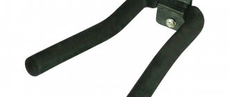
In order to perform the removal itself, you will need one of the following tools:
- open-end wrench 15 or special pedal wrench;
- small adjustable wrench;
- key from a bicycle kit.
To remove contact bicycle pedals you need a special tool - a puller. It is also used for removing connecting rods. Having chosen from this set the one that is most convenient, you can get to work.
Transferring the circuit to a breadboard (soldering)
After successful testing and verification of functionality, you can move on to transferring the circuit to a breadboard. Standard Stripboard sizes may be larger than required, so any excess can be cut off, reducing the working surface.
Trimming the breadboard
Despite the isolation of the copper strips from each other, it is recommended to remove those that are not involved in the circuit. This can be done with a small drill, which can easily handle copper and break the bond. It is better to remove any remaining copper.
Breaking copper bonds with a drill
After you finish soldering and the circuit is completely transferred to the breadboard, we advise you to check the operation of the pedal again.
The future pedal assembled
Placing the board into the case and completing assembly
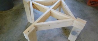
Once the circuit has been transferred and soldered onto the breadboard, you can move on to the final stage - assembling the case. To do this, we need an aluminum blank, which you can buy on AliExpress for 300-500 rubles.
Billet aluminum body with drilled holes
Having decided on the location of all the elements inside, drill four holes in the case: for the power connector, input and output jacks, and volume control. For drilling, it is better to use a step drill, if one is at hand.
Assembling your own pedal and not coming up with a unique visual design for it is a crime worse than those committed by Grindelwald. There shouldn’t be any problems with choosing paint, since today there is a wide variety of aerosol cans on the market designed to work with a wide variety of surfaces. You can always use fashionable stickers as a graphic component, unless, of course, you have artistic skills.
The result of all actions will be a real custom fuzz. If desired, the circuit can be complicated by adding the same bypass to the circuit. As you can see, building your own effects pedal is not as difficult as it seems.
Source
About bicycles
The most popular are mountain bikes, which appeared in the 70s. Their appearance is associated with improvements in the quality of materials and inventions in braking and mechanical devices.
Among mountain bikes there are several subtypes. All models have a lot in common: hard steering; brakes on both wheels; often two transmission switches.
Most often, aluminum hardtail models with suspension front forks are purchased. They are designed for mid-seat seating, equipped with disc brakes and additional equipment: trunk, fenders, etc.
The speed of a bicycle is influenced by the following factors: aerodynamic resistance; condition of the road surface; wind strength and direction; technical characteristics of the bike.
Experienced cyclists advise ways to improve the technical characteristics of a bike.
Tires have a big impact on driving speed. Regular mountain bikes have tires with spikes. It has a small area of adhesion to the asphalt, so it dampens the bike’s roll.
For asphalt roads, slick tires with a smooth surface and drainage grooves are effective, which provide the bike with high inertia and do not slip on a wet road.
There is a rubber option - semi-slick, which has a smooth surface in the middle and spikes only at the edges. Wheels with such rubber stabilize the bike well when cornering.
With slick tires, the cyclist spends less energy on accelerating and maintaining speed, the bike travels a longer distance without pedaling, and the speed increase can reach up to 10 km/h.
While riding, the suspension fork sways, so the cyclist's efforts are dampened and the speed does not increase. If you install a rigid (rigid) fork or a shock-absorbing fork with locking, the speed will increase.
The carbon rigid fork is lightweight and lightly cushioned due to the elasticity of the material.
An aluminum fork is stiffer, costs less, but weighs more.
When replacing, the size of the rigid fork is selected to match the geometry of the frame, and the existing angle of the steering column is maintained.
The speed of the bicycle depends on the condition of the large sprocket. As a rule, it is replaceable.
For maximum speed, a large sprocket is installed at the front. On a traditional bike it has 42 teeth. After installing a 48-tooth sprocket, the driving speed increases.
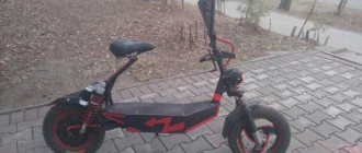
When riding, the cyclist presses the pedal with one foot, while the other leg does not work. Pedals have been developed to improve foot performance.
Contact models, which use a special cleat on the shoe and a groove on the pedal, use both feet. When one foot moves its pedal down, the other foot pulls the second pedal up.
There are pedals that fix the legs in the stirrups (toe clips). This fastening can be easily made with your own hands from a thin strap.
The speed of the bicycle increases if the “trampling” pedals are replaced with pedals that fix the legs.
The resistance to the headwind, and therefore the speed, depends on the cyclist’s position. A horizontal landing is considered ideal, which can be achieved in various ways.
Firstly, they raise or move the saddle, secondly, they change the stem of the steering wheel or lower it, and thirdly, they shorten the handlebars to shoulder width. In addition, there are sun loungers for the steering wheel. They have armrests for ease of control.
The riding speed depends on the technical condition of the bike. If you decide, provide quality service. To make it move faster, it is necessary: once a season to sort out all the nodes; replace worn bearings; adjust the brakes so that they do not touch the rim; clean the stars and derailleur rollers; wash the chain with gasoline and lubricate it with liquid lubricant; tighten the chain.
In conclusion, it should be noted that speed depends not only on the condition of the bicycle. First of all, the cyclist must have good physical fitness. High speed is possible if you ride a lot and watch your weight. So you've learned how to make a bike faster.