What is a stepper motor
According to the most popular definition, this is a machine that converts electrical energy (it receives it from the network) into mechanical energy by carrying out discrete (attention, not continuous, this is important) movements of the rotor.
Moreover, after each such action, the position of the dynamic part is fixed. All individual movements are of the same magnitude, and together they form a complete revolution (cycle). Therefore, by counting their number, you can easily and with high accuracy calculate the absolute position of the tool. Their total number, by the way, depends on a number of factors: the nature of the connection, the type of device, the method of specifying commands and other factors.
Operating principle of a stepper motor
- Voltage is applied to the terminals, due to which the special brushes begin to rotate.
- Under the influence of incoming pulses, the rotor is set to its initial position and then moves at the same angle.
- The microcontroller (in most cases, although other external control circuitry is possible) drives the gear magnets. The one to which energy is applied attracts the gear, thereby ensuring the rotation of the shaft.
- The remaining magnets are by default aligned with the leader, so they move along with it towards the next part.
- The gear rotates by switching electromagnets in order - from the main one to the next one and so on. At the same time, it is aligned with the previous wheel, which completes the cycle.
The step of the stepper motor is the algorithm described above, and it is repeated the number of times necessary to complete the technological operation.
An idea of the appearance and nature of functioning will be complemented by the following figure:
It is clear from it that the stator includes four windings arranged crosswise, that is, at an angle of 90 0 to each other. From here it is clear that discrete movement will be carried out by the same amount of degrees. If the voltage is applied alternately - U1, U2, U3 and so on - the rotor will make a full revolution, and then go to the second circle, that is, it will begin to rotate - until it needs to be stopped. Well, to change the direction of its movement, it is enough to use the turns in the reverse order.
How to make a wind generator
It is mounted on the motor shaft and additionally secured with screws, and plastic blades are attached to the flanges. The photo shows two blades, but you can make four by screwing two more similar ones at an angle of 90º. For greater rigidity, a common plate should be installed under the screw heads. It will press the blades more tightly to the flange.
Plastic products do not last long. Such blades will not withstand prolonged wind with a speed of more than 20 m/s.
The generator is inserted into a piece of pipe to which it is bolted.
A weather vane is attached to the end of the pipe, which is an openwork and lightweight structure made of duralumin. The wind generator is supported on a welded vertical axis, which is inserted into the mast pipe with the possibility of rotation. A thrust bearing or polymer washers can be installed under the flange to reduce friction.
What are stepper motors: let's look at their varieties
The operating modes of the motor determine 2 characteristics: the step size and the force applied to move. You can vary them by changing the connection method, the structure of the windings or shaft.
Accordingly, the classification of drives is carried out according to the following parameters:
- Regarding the design of the rotor, its structure plays a key role, since the specifics of interaction with the electromagnetic field of the stator depend on it. There are 3 options, and we will consider each of them below, with all the features, pros and cons.
- By type (number of windings) - as their number increases, the rotation becomes smoother, but at the same time the cost of the power unit increases, although the torque remains unchanged. They can be uni- and bipolar, in the first case they are connected with a branch from the midpoint, in the second - through 4 outputs.
Now let's pay attention to the structure of the shaft.
Variable reluctance stepper drives
As the name suggests, it does not have its own source of a constant field; In addition, its rotor is made of soft magnetic material and has a toothed shape. Through the contact areas closest to the stator, closure occurs - with attraction to the poles, providing discrete movements. In its design, it is similar to a gear, in which the rotational force appears due to opposing pairs and alternating current flow.
The key advantage is that there is no stopping moment, because the field, which in other cases can influence the reinforcement, is simply absent. You get a synchronous power unit in which the rotor and stator turn simultaneously and in unison.
Having the same dimensions as other varieties, these models develop less torque. The movement is carried out by 5-15 degrees, and this is relatively rough and often inaccurate. This explains the somewhat limited scope of application of a reactive stepper motor: where a motor of this type is used, it is in specific machines, all the parts of which are manufactured by the manufacturer independently.
With permanent magnets
Again, it is immediately clear what their peculiarity is - the presence of their own source of a constant field, which is
the basis of a moving element and containing 2 or more poles. It is the latter that ensure rotation of the rotor by applying voltage to the windings and attraction/repulsion.
The movement can be carried out either completely perpendicular to the previous position, or halfway; By increasing the number of magnetic pairs, you can adjust the length, and therefore the number of discrete movements, bringing their total number to 48 per full revolution. This allows you to very accurately install the working tool in the right place and is a competitive advantage of the power unit.
Hybrid
The design of this type of stepper motor was developed to combine the advantages of the previous two. It is a cylindrical field source, magnetized longitudinally, that is, a pair of poles with special surfaces - with applied teeth. The latter provide excellent retention without reducing torque.
Practical advantages:
- small step - 0.9-50 - which allows precision positioning due to a large number of discrete movements (up to 400 per cycle);
- high speed and smooth operation.
Yes, they are more expensive than the two previous types, since they are more difficult to manufacture, but this is a relative minus. Due to their advantages, these are the most common options today, used in the most critical cases: installed in CNC machines, in modern robotics devices, on medical and office equipment.
Experiment No. 2. TMC2208 + ATtiny44
TMC2208 is the name of the driver chip for controlling bipolar stepper motors; the module based on it is also called, which is produced for installation in homemade (and not only) 3D printers and has a unified pinout arrangement.
A lot has been said clearly about this module here. A lot has been written on the Internet about how to install it in your 3D printer, but we are interested in how to connect the module to a microcontroller, so let’s figure it out.
The characteristics of the microcircuit are impressive (only for impressionable people):
- logic part supply voltage: 3-5V;
- motor supply voltage 5.5-36V;
- peak current 2A;
- setting the maximum motor current;
- UART interface support for both control and configuration of internal registers;
- automatic power off;
- support for microstepping motor control up to 1/16th step.
It is very simple to control; in fact, you only need two pins of the microcontroller. We connect one to DIR - we indicate the direction of rotation of the motor, the other we connect to STEP - when a pulse is applied, the microcircuit performs the necessary manipulations with the currents and voltages on the motor windings and it takes one step.
The connection diagram will look like this:
Additionally, I used the EN pin to turn off the motor and not keep the windings energized for a long time.
Source code in WinAVR environment
#define F_CPU 8000000UL // specify the frequency in hertz // fuses must be set L: E2; H:DF; Ex:FF; // this will be a frequency of 8 MHz from the internal oscillator with the clock prescaler turned off (enabled by default and equal to #include // connect the AVR library #include // connect the delay library #include // connect the interrupt library // control the standard LED #define LED_pin PA5 #define LED_ON PORTA |=(1<<<<<
- < <<0) { // haven't done the required number of steps yet STP_ON; // take one step delay_microsecond(100); // pulse duration 100 μS STP_OFF; delay_millisecond(step_delay); // pause between pulses step_quantity—; } } int main (void) { DDRA |=(1<< <
Before you start everything, you need to pre-configure the module. First, set the desired microstep mode. Secondly, set the desired maximum motor current.
With microstepping everything is simple. Pins MS1 and MS2 are responsible for this.
I note that the microcircuit does not change the voltage abruptly, but does it “smoothly”, but since the microcircuit is digital, the output is not a smooth signal, but a signal with a small step; according to the documentation, it breaks each step into 256 microsteps. This was done to increase smoothness, reduce noise from the engine and, in theory, should not allow the structure to which it is screwed to resonate. In short, everything to make the 3D printer work more quietly.
To set the motor current, you need to measure the voltage at the Vref contact, which is shown in the figure. You can change the voltage value using a potentiometer installed next to the contact. The voltage at the contact will be proportional to the motor current, and the relationship will be as follows:
Vref = I*1.44;
Our motor needs approximately 150mA, so Vref = 0.216V
. Installing...
It is understood that the microcircuit provides an increase in current by increasing the voltage on the winding. Therefore, you need to make sure that this voltage is enough. But I think 5V should be enough for that little motor.
Let's test the operation of the motor with different microstepping modes and see what happens (pause between microsteps is 10ms):
You can notice that the movements of the motor have become smoother (compared to the previous experiment), but the characteristic 16 steps are still observed quite clearly.
Well... apparently this is a feature of stepper motors with a rotor made of permanent magnets
. It should also be noted that the motor in this mode heats up almost as much as in full-step mode with two phases. This is understandable, the windings are constantly under voltage, and heat is continuously generated.
I believe that for such motors the use of such a driver, and indeed microstepping modes in general, is not very advisable.
Closed and open-loop systems
Axis positioning systems allow intelligent controllers to position equipment with exceptional accuracy. A command is issued to move to the desired point in three-dimensional space and the machine responds very quickly and accurately.
Positioning systems typically use one of two methods: closed-loop and open-loop systems. So what is the difference between these two approaches to positioning?
Closed-loop systems typically use servo motors to control the speed and position of a moving axis. Servo motors work just like any regular motor, when power is applied to them they rotate. This rotation takes on a continuous smooth motion. The job of a servo motor is not only to drive the motor, but also to precisely control the speed.
Along with speed, position feedback is also required in a closed-loop system. This is usually provided by an encoder or linear scale. Positional feedback to the machine's controller allows it to move quickly to a target location and then smoothly slow down to settle on the target.
Open loop systems do not have a feedback device to control speed or position. Instead, the distance to be covered from the current location is divided by the machine control system into several precise steps of a certain size. The control system also determines the optimal system speed curve based on predefined parameters. The commands are then sent to the stepper motor in the form of pulses. The job of a stepper motor driver is to convert command pulses into actual motor drive steps, then the stepper motors advance through these steps to achieve the desired result.
Experiment No. 3. ATtiny44 driver
Let's return briefly to the first experiment and remember that the EN1 and EN2 inputs of the driver chip are connected to the OC0A and OC0B pins of the microcontroller.
This means that we can apply a PWM signal generated by the TIMER0 timer there and thus change the voltage applied to the motor windings and accordingly regulate the current that will flow through them. According to the datasheet for the ATtiny44 microcontroller, the maximum current that one pin can produce is only 40mA. Moreover, it is not indicated for what type of current (pulsating or constant) this characteristic is. She just exists and she’s like this...
I must say that I have been familiar with ATMEL microcontrollers for more than 7 years. And not once did I have the desire to check this line from the datasheet.
Perhaps the manufacturer is simply playing it safe and in fact can issue more, or maybe this is really the maximum that one pin can issue.
We'll find out. But first you need to find out at what minimum current the motor can rotate at all.
Using the circuit from the first experiment, we adjust the value of the current through the windings to be equal to 40 mA. We start in full-step mode with two phases (since the torque will be higher):
Great! At 40mA the engine started successfully!
The minimum value of the winding current required for stable operation of the motor was also identified, and it is equal to 30 mA.
Of course, the torque will be significantly lower, but the very fact that we were able to start the motor with such low power consumption is important to us.
The connection diagram of the stepper motor to the microcontroller will be as follows:
Since each pin of the microcontroller works as a half-bridge (it can switch the output of the microcircuit either to Vcc or to GND), then to control a bipolar stepper motor we need 4 pins of the microcontroller.
Program code:
Source code in WinAVR environment
#define F_CPU 8000000UL // specify the frequency in hertz // fuses must be set L: E2; H:DF; Ex:FF; // this will be a frequency of 8 MHz from the internal oscillator with the clock prescaler turned off (enabled by default and equal to #include // connect the AVR library #include // connect the delay library #include // connect the interrupt library // control the standard LED #define LED_pin PA5 #define LED_ON PORTA |=(1<<<<<<<<<<0) { // the loop runs until all steps are completed switch(direction) { // depending on the set direction of rotation, we increment or decrement the step counter case 'F': if(step_counter<3) { step_counter++; } else { step_counter=0; } break; case 'B': if(step_counter>0) { step_counter—; } else { step_counter=3; } break; } switch(phase) { // select single-phase or two-phase mode case 1: switch(step_counter) { // assign the current step case 0: step_1_two_phase_DL(); break; case 1: step_2_two_phase_DL(); break; case 2: step_3_two_phase_DL(); break; case 3: step_4_two_phase_DL(); break; } break; case 2: switch(step_counter) { // assign the current step case 0: step_1_two_phase_DL();
break; case 1: step_2_two_phase_DL(); break; case 2: step_3_two_phase_DL(); break; case 3: step_4_two_phase_DL(); break; } break; } delay_millisecond(step_delay); // pause between steps sets the rotation speed of the engine step_quantity—; } } void PWM_init (void) { // PWM initialization function DDRB |=(1<<<<<<<<<<<<<<<<<< Let me explain a little how this program works. This is a modified code from the first experiment. How I said above, 8-bit TIMER0 will be used to generate a PWM signal at outputs OC0A and OC0B. The timer is set to FastPWM mode with a prescaler of 8 (the signal frequency at 8 MHz of the microcontroller clock generator is 3906 Hz).
To change the polarity of the signals on the windings, the microcontroller pin is switched from Vcc to GND by changing the corresponding bit in the PORTx register and changing the PWM duty cycle by writing values to the OCR0A and OCR0B registers (values were selected experimentally).
And here it is:
The circuit design course taken in the first year of the institute suggests that the multimeter shows the rms value of the voltage and current in the motor.
The stepper motor rotates from microcontroller pins without drivers!
But here we do not go beyond the capabilities of the microcontroller, at least according to what they write in the documentation. In this mode, the microcontroller and motor can work for a long time. Indeed, the experiment lasted 20 minutes. During this time, there were no missed steps, no controller resets, no overheating (neither the motor nor the controller).
Let's throw all precautions aside
Let's remove PWM from the experiment and directly control the microcontroller pins using the PORTx registers.
Let's see what happens to the microcontroller after this. It works... with a maximum current of 51mA... Well... unexpectedly, it seems that this is the maximum current that one pin of the microcontroller can supply? If I'm wrong, correct me.
In any case, the video from YouTube did not deceive. really control this motor without any drivers
.
What drivers for 3D printer stepper motors can you buy?
1. TMC2208, TMC2130, TMC2100. Output current per winding with additional cooling is up to 2 A, peak output current 2.5 A. Power supply voltage: 4.75 - 36 V. Step crushing: 1/2, 1/4, ⅛ and 1/16 with the possibility of interpolation up to 1/256. It is used to reduce noise when working with 8-bit microcontrollers. It can be used in devices with low-power operating modes, as well as in equipment where high energy efficiency of motors is in demand. The TMC2208 is built on a chip from Trinamic and is capable of delivering up to 2.5 A per winding, which is enough for use in 3D printers and CNC. At the same time, the problem of noisy operation of stepper motors is solved due to effective algorithms for generating control pulses (StealthChop2™) and current control.
Quiet drivers, we recommend installing them. It costs more than the others, about $15.
2. A4988 Permissible output current per winding with additional cooling - up to 2 A, without cooling - up to 1 A. Power supply voltage: 8-35 V. Advantages of the A4988 driver - the presence of protection against overloads and overheating, the ability to adjust the current and several options microstepping. Step crushing: 1, 1/2, 1/4, 1/8, 1/16. 9V is significantly quieter than 12V, without loss of torque. A sharp increase in sound occurs from 11V to 12V. Cost about 6 $.
We recommend reading: What is a zener diode used for and how does it work?
4. DRV8825 Permissible output current per winding with additional cooling – up to 2 A. Power supply voltage: 8-45 V. Electrical and mechanical compatibility with the A4988 driver. Step crushing: 1, 1/2, 1/4, 1/8, 1/16, 1/32. According to reviews, they have a design flaw that results in the appearance of defects on the surface of the print in the form of vertical stripes (zebra stripes). The disadvantage can be eliminated by installing TL-Smoother, but it will be much more cost-effective to buy TMC2208 instead. Cost about 6 $.
Experiment No. 1. L293D + ATtiny44
As we know, to control a bipolar stepper motor, it is necessary not only to apply voltage to two windings in the required sequence, but also to change the direction of the current in these windings, and to do this independently of each other.
To do this, each winding needs its own H-bridge. In order not to block it from transistors, a ready-made one was taken in the form of the L293D microcircuit. Another advantage is that the microcircuit has special pins Enable1 and Enable2, which turn each bridge on and off. They can be used to supply a PWM signal, thereby making it possible to control the supply voltage of each bridge. Why this might be needed, we will see further. In addition, the L293D can switch voltages up to 36V and deliver up to 1.2A per channel
, which should be enough to power the windings of our motor.
So, the diagram:
The control inputs of the L293D are connected to the outputs OC0A and OC0B, which will allow them to be supplied with a PWM signal in the future.
We will flash the controller through an in-circuit programmer (not shown in the diagram). This is what the assembled circuit looks like on a breadboard:
And this is how our experimental subject is located:
Now you can start experimenting.
Let's calculate the current that will flow through the motor windings when connecting them to a voltage of 5V:
I=U/R = 5V/26Ohm = 190mA
Quite small. I wonder how long it can hold this current and not overheat.
Let's connect an ammeter and a voltmeter to the circuit of one of the windings, and measure the corresponding values when power is supplied to this winding through the driver.
When the voltage drop across the winding is 2.56V, the ammeter shows a current of 150mA
, and it is clearly noticeable how the current strength begins to drop as the windings heat up. It should be noted that it does not heat up that much.
Having made sure that the 5V voltage does not pose a danger to the motor, let’s try to twist it in different directions. And now we will say a few words about the operating modes of the stepper motor.
This is pretty well said here.
We won’t repeat ourselves, but remember that a stepper motor can operate in three modes:
- Full-step single-phase is when voltage is applied to only one phase of the motor at a time, the rotor takes a step, then the current phase turns off and the next one turns on.
- Full-step two-phase is when voltage is applied simultaneously to two phases of the motor, while the rotor is simultaneously attracted to two windings, which creates greater torque.
- The microstep mode in this case implements the same principle as the full-step two-phase mode, that is, two windings operate simultaneously, but the voltage (and, as a consequence, the current) is distributed unevenly between them. In fact, this means that we can put the motor in an unlimited number of positions (in practice, of course, this cannot be done). Positioning accuracy increases.
Let's try to implement the first two modes on the L293D chip and for the microstepping mode we will leave the special driver from the second experiment.
The source code of the program looks like this:
Source code in the WinAVR environment
#define F_CPU 8000000UL // specify the frequency in hertz // fuses must be set L: E2; H:DF; Ex:FF; // this will be a frequency of 8 MHz from the internal oscillator with the clock prescaler turned off (enabled by default and equal to #include // connect the AVR library #include // connect the delay library #include // connect the interrupt library // control the standard LED #define LED_pin PA5 #define LED_ON PORTA |=(1<<<<<<<<<<<<<<<<<<<<<<<<<<<<<<<<<<<<<<0) { / / the loop is executed until all steps are completed switch(direction) { // depending on the set direction of rotation, we increment or decrement the step counter case 'F': if(step_counter<3) { step_counter++; } else { step_counter=0; } break; case 'B': if(step_counter>0) { step_counter—; } else { step_counter=3; } break; } switch(phase) { // select single-phase or two-phase mode case 1: switch(step_counter) { // assign the current step case 0: step_1_two_phase_DL(); break; case 1: step_2_two_phase_DL(); break; case 2: step_3_two_phase_DL(); break; case 3: step_4_two_phase_DL(); break; } break; case 2: switch(step_counter) { // assign the current step case 0: step_1_two_phase_DL(); break; case 1: step_2_two_phase_DL(); break; case 2: step_3_two_phase_DL(); break; case 3: step_4_two_phase_DL(); break; } break; } delay_millisecond(step_delay); // pause between steps sets the rotation speed of the engine step_quantity—; } } void PWM_init (void) { // PWM initialization function DDRB |=(1<<<<<<<<<<<<<<<<<
Full step mode. Single phase
The motor makes 16 steps per revolution.
Moreover, the steps for the two phases do not have the same angular magnitude. I don't know what this is connected with. Maybe this is the engine design? Let's look at the maximum frequency of steps that he can achieve in this mode without skipping them.
The minimum delay between steps is 2ms, which means 500 steps/second. Not bad, that's 31 rpm = 1850 rpm.
Full step mode. Two phases
Please note that in this case the steps are smoother, they are the same in size (in any case, more the same than in the previous case).
Naturally, in this case, two windings are simultaneously energized and heat transfer increases. The engine gets quite hot within a few seconds, so I stopped the experiment.
What about the maximum cadence? 500 steps/second; 31 rpm = 1875 rpm.
I must say that for a stepper motor it is quite fast. This is due to the small number of magnetic poles on the rotor.
Let's continue...
Smoothing device TL-Smoother
A board that connects the stepper driver and stepper motor, reducing noise and vibration in your 3D printer, reducing the risk of zebra stripe defects.
This small board has eight rectifier diodes that improve the stepper motor waveform, particularly for older, cheaper stepper drivers such as the DRV8825 and A4988. Improving the waveform reduces engine noise by reducing vibration. Since vibrations are reduced, print quality also improves. Just install the board between the driver and the stepper motor, the orientation doesn't matter. For convenience, the kit includes a small 4-wire connector, 20 cm long, to connect the board to the electronics. Cost about 7 $
Zebra stripe or moire defect
Connecting stepper motors
The choice of stepper motor connection diagram depends on:
- number of wires in the drive;
- way to start the mechanism.
Existing engine models have 4, 5, 6 or 8 wires. A device with four wires can only be connected to bipolar devices. It is equipped with two phase windings, each of which has two wires. To connect the driver step by step, you need to identify pairs of wires with a continuous connection using a meter.
In a six-wire mechanism, each winding has two wires and a central tap. The engines of this model are characterized by high power and are connected to both bipolar and unipolar actuators.
In the first case, one center tap of each winding and one end of the wire are used.
In the second case, all six wires are used. The separation of the wire is carried out using a measuring device.
The difference between a five-wire motor and a six-wire model is that the center terminal connection is a solid cable that goes to the center wire.
Since separating one winding from another without breaking is not possible, it is necessary to determine the center of the wire, and then connect it to other conductors. This will be the safest and most effective solution. Then the engine is connected to the network and its functionality is checked.
To successfully operate the mechanism, you need to keep in mind the following nuances:
- The rated voltage is produced by the primary winding at constant current.
- The change in initial torque speed is directly proportional to the change in current.
- The rate at which linear torque decreases at subsequent high speeds depends on the inductance of the windings and the drive circuit.
Typical SD connection diagrams
Connection diagram of a 6-pin stepper motor to the GeckoDrive driver (bipolar serial connection of windings)
Connection diagram for an 8-pin stepper motor with bipolar parallel connection of windings to the GeckoDrive driver
Connection diagram for an 8-pin stepper motor with a bipolar serial connection of windings to the GeckoDrive driver
Stepper motor control
There are three stepper motor control modes:
• full step
• half-step
• microstepping.
Full step control mode
The first method was described in the examples above. This is alternating phase switching, the phases do not overlap, at any time only one phase is connected to the voltage source.
The method is called in English one phase on full step - one phase per full step. The rotor balance points coincide with the stator poles. The disadvantage of this mode is that at the same moment half of the windings are used for a bipolar motor, and only a quarter for a unipolar one.
There is a variant of a full-step control mode in which two phases are turned on at the same time. It's called two-phase-on full step - two phases per full step. With this method, the rotor is fixed between the stator poles by supplying power to all windings.
half-step mode
This allows you to increase engine torque by 40%. The pitch angle does not change, the rotor is simply shifted by half a step in equilibrium. This method allows you to get twice as many steps from the engine per rotor revolution.
Every second step one phase is turned on, and between them two phases are turned on at once.
As a result of such commutation, the angular movement of the step is reduced by half, or the number of steps is doubled. It is not possible to obtain full torque in half-step mode.
Despite this, the half-step mode is often used. Using very simple methods, it doubles the number of engine steps.
It must be remembered that for both modes it is true that when the engine is stopped and voltage is removed from all phases, the engine rotor is in a free state and can move due to mechanical influences.
microstepping mode
To fix the position of the rotor, it is necessary to generate a holding current in the motor windings. This current can be significantly less than the rated current.
The ability of the stepper motor to fix its position when stopping allows you to do without mechanical clamps, braking systems, etc.
Control of brushless motors
A controller is required to control a stepper motor. The controller is a circuit that supplies voltage to one of the stator coils. The controller is made on the basis of an integrated circuit of the ULN 2003 type, which includes a set of composite keys. Each switch has protective diodes at the output, which allow you to connect inductive loads without requiring additional protection.
An H-bridge system is used to control brushless motors. Which allows you to switch the polarity to reverse the stepper motor. It can be performed on transistors or microcircuits that create a logical chain for moving keys.
As you can see, voltage is supplied to the bridge from the power source V. When contacts S1 – S4 or S3 – S2 are connected in pairs, current will flow through the motor windings. Which will cause rotation in one direction or another.
With controller
The controller device allows you to control the stepper motor in various modes. The controller is based on an electronic unit that generates groups of signals and their sequence sent to the stator coils.
To prevent the possibility of damage in the event of a short circuit or other emergency situation on the motor itself, each terminal is protected by a diode, which will not allow a pulse to pass in the opposite direction.
Homemade wind generator based on a stepper motor
A stepper motor (SM) for a printer is suitable as a generator for a windmill. Even at a low rotation speed, it produces about 3 watts of power. The voltage can rise above 12 V, which makes it possible to charge a small battery.
- Principles of use
- Electrical part
- How to make a wind generator
- Conclusion
Principles of use
Wind turbulence in the surface layers, characteristic of the Russian climate, leads to constant changes in its direction and intensity. Large wind generators with a power exceeding 1 kW will be inertial. As a result, they will not have time to fully unwind when the wind direction changes. This is also hampered by the moment of inertia in the plane of rotation. When a side wind acts on an operating wind turbine, it experiences enormous loads, which can lead to its rapid failure.
It is advisable to use a low-power wind generator, made by yourself, which has insignificant inertia. With their help, you can charge low-power mobile phone batteries or use them to illuminate your dacha with LEDs.
In the future, it is better to focus on consumers that do not require conversion of the generated energy, for example, for heating water. A few tens of watts of energy may well be enough to maintain the temperature of hot water or to additionally heat the heating system so that it does not freeze in winter.
Electrical part
As a generator, you can install a stepper motor (SM) for a printer in a windmill.
Even at a low rotation speed, it produces about 3 watts of power. The voltage can rise above 12 V, which makes it possible to charge a small battery. Other generators operate effectively at a rotation speed of more than 1000 rpm, but they will not be suitable since the windmill rotates at a speed of 200-300 rpm. A gearbox is needed here, but it creates additional resistance and also has a high cost.
In generator mode, the stepper motor produces alternating current, which can easily be converted to direct current using a pair of diode bridges and capacitors. The circuit is easy to assemble with your own hands.
By installing a stabilizer behind the bridges, we obtain a constant output voltage. For visual control, you can also connect an LED. To reduce voltage losses, Schottky diodes are used to rectify it.
In the future, it will be possible to create a wind turbine with a more powerful motor. Such a wind generator will have a high starting torque. The problem can be eliminated by disconnecting the load during start-up and at low speeds.
How to make a wind generator
You can make the blades yourself from PVC pipe. The required curvature is selected if you take it with a certain diameter. The blade blank is drawn on the pipe and then cut out with a cutting disc. The propeller span is about 50 cm, and the width of the blades is 10 cm. Afterwards, you should grind the sleeve with a flange to the size of the motor shaft.
DIY stepper motor controller
The task is simple: using the ready-made circuit and program of Pavel Bakhtinov from this forum, lay out a printed circuit board, assemble and debug a controller for controlling stepper motors installed in the mount of an astronomical telescope. Next, you need to make a decent case and control panel. It all starts with the details (Murphy’s law immediately comes to mind: “No talent could survive the passion for details”):
Working on the diagram:
We lay out the printed circuit board:
The photo template is ready:
Here I need to say a few words about my KNOW-HOW in making photo masks for transferring a design onto a printed circuit board.
Usually I print them on a printer - often on an inkjet, less often on a laser, because... The thermal film shrinks unexpectedly after heat treatment in the laser (and templates are needed for both sides), so it was impossible to align the two templates with sufficient accuracy (up to 0.15 mm).
The inkjet printer reproduces the dimensions well, but does not fill the paths with black densely enough; in some places they are still visible. A solution to this problem was soon found: we print not with pure black, but a little lighter towards yellow - the printer begins to add yellow (opaque to UV radiation) and tracks to the black ink, although they look more transparent, after photo transfer they turn out denser, practically without Izyanov.
We recommend reading: How to make a radio-controlled airplane at home
The main thing is to choose the exposure:
The process of etching the printed circuit board is in progress:
Fully etched:
We drill holes with a diameter of 0.7mm to 1.5mm using a homemade drilling machine:
The soldering iron is old and remote:
We stuff the board with details:
All parts are sealed:
The reverse side of the board, the debugging process has begun:
This is how we will place the heating elements (those above in the figure on this side of the board are an integrated stabilizer and two microcircuits - motor drivers) on such beautiful radiators:
At this time, work has begun on the remote control. The main thing in the control panel, I think, is ergonomics, as far as it is appropriate to apply this to the box that will be obtained after assembly on domestic LARGE but reliable microbuttons.
Stepper motor from an old printer as a generator
Having disassembled the old printer, I got this beauty:
What is this? Stepper motor, there are plenty of motors of this type in printers and CD/DVD drives and in old floppies.
What can it be useful for, you ask? They make excellent alternators (thanks Tesla), and AC can be converted to DC without any problems. And what’s most interesting is that the alternating current during rectification can be multiplied using a voltage multiplier, ChipiDip will tell you about them:
I assembled a voltage doubler according to the classical circuit and connected it to one phase of the motor:
Capacitors of 10,000 uF are more than enough for the robot with my stepper.
Schottky diodes have a slightly higher efficiency than conventional silicon diodes, so I settled on them. My diodes are designed for a current of 5 Amps, so I’m not afraid of burning them.
I spun it a few times by hand and...
Let's try to make a spark:
The accumulated energy in the capacitors was even enough for two.
The voltage went above 20 volts, but you should not think that above 20 volts is already a lot, as you can see, the energy accumulated in the capacitors slightly spun up the computer cooler. As they taught in school, power (measured in Watts) is voltage multiplied by current, and the current is small, which can be seen in the video below:
The power obtained by hand may be small, but the cooler spins a little faster than through a conventional bridge rectifier, and you can also assemble another doubler and connect it to the second free phase and by connecting it in series or in parallel you can double the current or voltage.
My channel is on YouTube, subscribe, it will be more interesting.
Source
SD controllers
Controllers are switching boards used to convert control commands coming from a PC into a sequence of pulses for drivers. The board may have additional functionality - connectors for connecting limit stops, power relays, connectors for spindle control. Connects to a computer via LPT or USB interface.
Multichannel SD drivers are a device that combines SD drivers and a switching board. They connect to a PC and directly control the SD. The controller also includes such functionality as a coolant timer, a PWM converter for the inverter, power relays, connectors for connecting linear movement limitation sensors. Drivers can be executed for different numbers of SDs.
Advantages and disadvantages of a stepper motor
The advantages of using a stepper motor include:
- In stepper motors, the angle of rotation corresponds to the number of electrical signals supplied, while after stopping the rotation, the full torque and fixation are maintained;
- Precise positioning – provides 3 – 5% of the set step, which does not accumulate from step to step;
- Provides high speed start, reverse, stop;
- It is highly reliable due to the absence of rubbing components for current collection, unlike commutator motors;
- The stepper motor does not require feedback to position;
- Can produce low speeds for a directly applied load without any gearboxes;
- Relatively lower cost compared to the same servos;
- A wide range of shaft speed control is provided by changing the frequency of electrical pulses.
The disadvantages of using a stepper motor include:
- A resonance effect and slippage of the stepper unit may occur;
- There is a possibility of loss of control due to lack of feedback;
- The amount of electricity consumed does not depend on the presence or absence of a load;
- Difficulty in control due to the design of the circuit
How to connect a stepper motor without a controller
Stepper motors are found in cars, printers, computers, washing machines, electric shavers and many other everyday devices. However, many radio amateurs still do not know how to make such a motor work and what it actually is. So let's learn how to use a stepper motor. Stepper motors are part of a class of motors known as brushless motors. The stepper motor windings are part of the stator. The rotor contains a permanent magnet or, for cases with variable magnetic resistance, a gear block made of soft magnetic material. All switching is carried out by external circuits. Typically, the motor-controller system is designed so that it is possible to move the rotor to any fixed position, that is, the system is controlled by position. The cyclical positioning of the rotor depends on its geometry.
Homemade wind generator from a stepper motor
The simplest low-power wind generator can be assembled from an old scanner (or any other equipment containing a stepper motor).
To create a wind generator you will need:
- old scanner (or disk drive);
rectifying diodes (8 1N4007 diodes were used in the project);
capacitor 1000 µF;
voltage regulator LM7805;
plastic parts (see below);
- aluminum plates (any others can be used).
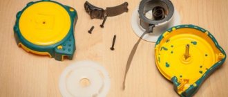
We remove the stepper motor from the scanner.
First, let's assemble the rectifier. For each phase of the motor (it is four-phase), we need 2 diodes, i.e. only 8 diodes. The output voltage will be stabilized using a 1000uF capacitor and an LM7805 voltage regulator.
Our wind generator can freely generate voltage of more than 5 volts, however, to charge mobile devices, 5V will be enough for us.
The next step is to cut out the blades from PVC pipe and attach them to the wind generator shaft.
In order for the wind generator to align itself with the wind, make its tail from a piece of plastic (fiberglass or similar materials).
All. You made a wind generator with your own hands.