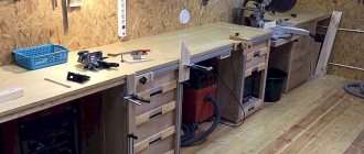
We make a third hand with two existing ones.
As a continuation of the laminate design, we will make a device that is often called the “Third Hand”. First, let's see what our smaller brothers offer us. Option 1:
There is too little flexibility for my applications.
Option 2:
There is enough flexibility, but how reliable these elements are and how much force they can withstand, I don’t know, and they cost so much that I don’t want to check them. Well, I wanted the base to be flat and have a larger area.
So I decided to do it myself. This is the option we got:
The base is my favorite piece of laminate. Flexible tentacles are made from this stuff:
The clips are regular alligator clips. I thought for a long time about how to attach them so that on one side they fit tightly, on the other they could be replaced when they break. First I tried this option:
These are contacts from the following terminal blocks (AAA battery in the background):
But the result turned out to be so-so. When the crocodile rotated slightly, the clamp loosened and the crocodile began to dangle. Yes, and it looked too massive.
The next option was:
Here the tube that comes with the crocodile is pressed onto it. From the point of view of use, the option turned out to be very good. And it fits tightly, and can be rotated without loss of tightness, and can be removed. But this option has a couple of significant disadvantages. These tubes are not sold with all crocodiles. But an even bigger drawback is that the size must very accurately match what is needed. A little more of the tube and it dangles, a little less and you won’t be able to tighten it.
So I thought further and tried this option:
Here are ordinary polymer threads, wound with force on a crocodile and secured with glue (the threads are secured with glue so that they do not unwind, not the crocodile). Despite some, at first glance, collective farm appearance, it looks quite decent. But most importantly, the result when using this option is excellent. It rotates without loosening and can be removed easily. When replacing the crocodile, winding a new portion of thread takes a couple of minutes. And everyone has threads. Well, the cost of such a solution is close to zero. Therefore, I secured the rest of the crocodiles in the same way.
I secured the tentacles at the base with regular cyanoacrylate. A hole is drilled, tentacles are inserted there and a couple of drops of cyanoacrylate are inserted there, and that’s it.
In general, I planned to have more tentacles around the perimeter of the base, but for now four are enough.
Well, at the end there is a photo, as is customary, with a board hanging in the air for some reason:
PS. When I wrote the review, I found these other options:
But they cost even more than the ones I mentioned at the beginning of the review. When I made my version, I didn't see them. Either they appeared recently, or I was looking poorly. In general, this is almost my option, only here the attachment of the tentacles is organized even more flexibly - they are on magnets and can be rearranged to any place. The truth is how these magnets hold is still a question, however, they can be replaced. So those who have little time and a lot of money can search and buy such options. For those who have the opposite, they can repeat my version.
That's all, thank you everyone.
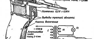
How to make a third hand with light
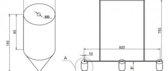
The idea of this homemade product belongs to the author of the YouTube channel KJDOT. The design of the device is very simple, it consists of:
- grounds;
- two flexible “arms” with clamps at the ends;
- stands with LED lamp.
To make flexible “arms”, the author uses pieces of thick wire. We bite off two pieces of the required length and attach “crocodile clips” to them.
The author also decided to make the stand for lighting flexible - we make it from a single-core wire with thick insulation (in principle, you can use the wire from which the “arms” are made.)
As a base, the author uses a piece of rectangular board - board, plywood, chipboard or MDF are suitable for this.
We cut out the base of a suitable size, make markings and drill 3 holes in it: two on the sides of the base, and one in the middle of the board (at a distance of 1 cm from the back wall).
We insert prepared pieces of wire into the drilled holes and fix them with superglue (or you can use hot melt adhesive).
After that, using a chisel, we make a seat for the connector for the Krona battery. We attach it with superglue.
We connect the wires that come from the connector to the LED lamp. We attach the lamp itself to the top of the stand.
Heat shrink tubing can be placed on the “teeth” of the clamps to prevent them from damaging wires or soft parts during assembly or soldering.
For details on how to make a third arm for soldering with your own hands, see the video below.
Make a Third Hand Soldering Holder
Among the advantages of this design, it is worth noting the ease of assembly and low cost, since all the necessary materials can be easily found at home or in the workshop.
A selection of “third hands” - tripods and devices for holding small electronics, etc.
Hi all!
Electronics have recently become very shredded and it is not always convenient to do it yourself when working with small circuit boards, wires, etc. Sometimes outside help is needed to hold the board, solder a wire to it, replace some component, or take measurements. You can do without outside help using the so-called “third hand” - a device in the form of a tripod with clamps, magnifying glasses, lamps and other amenities collected in one place.
This collection contains only such devices, but in different interpretations.
So, let's begin.
1. The simplest device, but often found on the tables of craftsmen.
You can buy it here
An axis with two clamps and a magnifying glass are attached to the cast-iron frame with hinged joints. The connections allow you to rotate the crocodiles and the magnifying glass with five times magnification (diameter 60 mm made of glass) at the desired angle. The device is not the most advanced in terms of functionality, but probably due to its low price, it is often found on specialists’ desks in electronics repair shops. Approximate dimensions: 125*70*50
2. The next "third hand" is similar to the previous one, but gives one more degree of freedom - both the clamps and the magnifying glass can be raised and lowered along the tripod, adjusting the desired position and magnification.
You can buy it here
The lens here is also glass, but with a diameter of 90 mm. There is parking for a soldering iron and a tray for all sorts of small items.
3. Tripod with two swivel clamps, two interchangeable lenses, soldering iron parking and LED light on a flexible leg.
Link here
The lenses here are plastic, there are two of them. Diameter 90 and 21 mm, magnification 3.5 and 10 times, respectively. The five backlight LEDs can be powered either from 3 AA batteries or from the included 5 Volt power supply. The axle with clamps is movable - you can move it closer to the central post or move it forward.
4. It's an interesting third arm, but it doesn't allow you to mount the board vertically.
Check price
There is adjustment of the reach and tilt of the lamp and the axis with clamps. Two acrylic lenses with a diameter of 75 and 20 mm. The backlight is powered by 3 AAA batteries or USB. Dimensions 200*95*170 mm. For stability, a steel plate is built into the base. There is parking for a soldering iron.
5. The next fixture is the next version of the previous third arm.
Check current price
There are already three acrylic lenses and trays have been added for all small things, which is sometimes convenient. Lens diameters 72, 30 and 20 mm. By combining lenses and the distance between them, you can achieve good magnification. Illumination is provided by 10 LEDs powered by 3 AAA or USB elements
6. A tripod with a backlight on a flexible leg, hinged clamps and the ability to install the board at any angle.
Link to product page
The set includes three acrylic lenses. Lens diameters 90, 34 and 34 mm. Magnification 2.5, 7.5 and 10 times. Backlight power -3*AAA or supplied power supply. They come with two lenses, and the third is made in the form of an influx on the largest one.
7. The next device is distinguished by a powerful backlight group and a neat appearance.
You can buy it here
Here, 18 LEDs and three lenses with a diameter of 108 mm (main), 21 mm (second interchangeable) and 30 mm (third interchangeable), giving magnification of 2.5, 6 and 10 times, will help you see small components. Illumination in both the upper and lower lamps with lenses. Included in the kit is a power supply for the backlight or 2*AA, you will have to buy it yourself.
8. The next “third hand” does not have a backlight or magnifying glass, but allows you to fix the board or part in almost any position. It looks futuristic, but the reviews are positive.
Find out the price
Six flexible holders with crocodiles are fixed to the frame. There are trays for small fasteners. The base is made of aluminum alloy, the weight of the structure is 550 grams.
9. A similar option, but with a more reliable attachment to the table and adjustable backlight.
You can buy it here
There are four holders here instead of six. Lens diameter 60 mm, magnification three times. As many as 42 LEDs were used, and the light control has 11 positions. Powered by USB 5V/1.5A. The length of the holder legs is 240 mm, the length of the lamp leg is 400 mm.
10. The selection ends with a device that I have been using myself for two years now. It often helps a lot.
Find out the price
The axle with three clamps can be raised, lowered vertically, pushed towards the rack or pushed forward, and also changed the angle of inclination of all three clamps at the same time. There is parking for a soldering iron and it is done correctly, the soldering iron does not fall through. There is a backlight and most importantly: the kit includes three lenses and a handle. The lenses can be mounted on a tripod, or they can be connected to the handle and get three full-fledged magnifiers. In addition, the handle itself contains a pair of LEDs and a compartment for two AA batteries. Sometimes it's very convenient. Acrylic lenses with a diameter of 90, 75 and 37 mm. Magnification 2.5, 5 and 16 times. The tripod is very stable and comes with a power adapter for illumination or can be powered by 4 AA batteries. The lints are of good quality, without sagging, deformation, etc.
Other possible adaptations
The kit of a good radio amateur and soldering master may include not only a third hand, lenses and microscopes, but also other devices and tools:
- special thermal tweezers (it is needed for retracting and maintaining contacts, heating elements are installed at its ends and this is how it differs from ordinary tweezers);
- miniature pliers or wire cutters (these devices remove insulation and defective wires);
- needle file (necessary for cleaning the soldering iron tip);
- technical awl and sharp knife.
Of course, this list is far from complete; to solve specific problems in the field of soldering microcircuits, additional devices may well be needed. More and more devices are appearing that allow you to test and repair electronic devices.
Binocular magnifier for soldering with head mount. Small DIY
A magnifier for SMD soldering is one of the necessary things for a radio amateur. But finding an inexpensive and convenient one is not so easy. Nevertheless, such goods do exist. For those who are interested in the topic, please cut So, why did the idea of such a purchase arise? I once had a magnifying glass with a headband and fixation on the bridge of the nose. A bit like this one. In terms of using it as a magnifying glass, everything was fine. But the constant pressure on the bridge of the nose made its long-term use completely uncomfortable. Then I bought magnifying glasses. I thought - since they are lighter, the previous problem will not exist. But no. I didn't like long-term use either. In the wake of the hype, I bought an electron microscope like this - https://aliexpress.com/item/item/1005001494859759.html According to the picture, everything was not bad, there were no delays on the screen when moving the soldering iron. But I was once again convinced of what I wrote about more than once. For comfortable soldering you need a stereo image. You can adapt to soldering under an electronic one, but it is completely uncomfortable. In general, I played with it and sold it. If you take a higher budget, you can buy a good binocular microscope. This is, of course, the best option. But the prices there are more or less adequate, from two to three hundred dollars and then they fly off into space. On the other hand, at home I don’t solder that often, but at work I already have everything I need. Therefore, I doubted the need for these expenses. One day I saw something similar by chance and decided to buy it and try it out. Let's take a closer look at it.
Magnifier parameters:
Mount - head-mounted with an adjustable headband Material - ABS for magnifying glass and acrylic for lenses Magnification - 1.2X 1.8X 2.5X 3.5X Weight - 170g Size - 240*200*125mm Lighting (flashlight) - removable Power - 3AAA
Everything is delivered in a bright cardboard box. On the box there is a photo of the magnifying glass itself, the characteristics of the lenses. The model is called MG81001-F.
Inside the box there is a magnifying glass mount, removable lighting, a set of lenses in a case, and a plug for a removable mount.
Box with lenses.
Closer.
Lens.
Lens material: acrylic. It scratches a little even when wiped with microfiber. On the other hand, they can be easily polished if necessary. The seller's website contains the following information:
Magnifications distance to viewed objects: 1.2X: 520-620mm 1.8X: 230-320mm 2.5X: 150-250mm 3.5X: 80-120mm
Actually, this is not true. Using a ruler, I measured the range of distances to the object when the eye comfortably focuses. It turned out like this:
1.2x: 12-30cm 1.8x: 8-16cm 2.5x: 6-12cm 3.5x: 5-10cm
Below are examples of photographs through lenses. dip8 chip. Some photos may be a little blurry - it is difficult to hold the phone at the required distance from the lens and the lens itself according to the Crop ruler is the same size in the photo.
1.2x 12cm
1.8x 8cm
2.5x6cm
3.5x 5cm
Now let's look at the magnifying glass mount. General form. A soft bow that fits to the forehead.
Lens mount.
Change sizes to suit different head circumferences.
Turning part tightening nut.
Bottom view of the lens mount. You can also see the hole for pushing the flashlight out of the mount.
Actually the flashlight itself.
There are two small neodymium magnets at its base. Quite strong.
Mounting slots for AAA batteries are also visible. The lever moves in a vertical direction relative to the body, the head of the flashlight itself moves up and down, left and right, relative to the lever. The light can be directed in any direction.
Let me digress a little from the topic. In fact, this form factor of the flashlight turned out to be very convenient to use. Recently I was repairing a shower stall, I removed the front wall and crawled under the pan. There is little room to turn around. With a regular flashlight it was very difficult to direct the light where needed. The family didn't help much either, because... They constantly had to tell them where to shine. I attached such a lantern with magnets to the nearest iron leg of the shower, directing the light where I needed it so I could work. I also use it periodically when I need to highlight something locally or work on something far from the working light.
LED with lens.
If you remove the plastic plug inside (located on the left), you can see the rotating mechanism and wires going to the top. There we will then remove some of the excess plastic in order to place the converter board. But that's later. In the DIY part of the review.
The upper half of the part with the LED is unscrewed. The board, LED, lens, microswitch (without fixation) are visible.
The board itself.
A microcircuit filled with compound is not a current stabilizer. Regular trigger. Yes, about the light. He's terrible
1. There is no current stabilization. As the batteries drain, the light becomes dimmer and dimmer. 2. The LED is bluish, with a poor spectrum.
This is what we will redo. I have already written several times that the backlight (for most Chinese backlights) needs to be converted either to LN or to LEDs with a warm color temperature and good CRI. Why? LEDs with a large blue hump in the spectrum have a peculiarity - they shine brightly, but, oddly enough, small details are poorly visible. This is due to the focusing characteristics of the eye in different parts of the spectrum. There are different studies on this matter. I once cited something similar eyepress.ru/article.aspx?24403 You can go straight to the results. Well, I also wanted to give up 3AAA and use two Ni-Mh.
So, the DIY part.
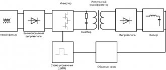
Remodeling scheme.
The converter used is MT3608. I used GW SBLMA1.EM-HQHS-A535-L1N2-65 LEDs. Don't be alarmed by the names . They are actually quite common. Osram just labels them that way. Datasheet docs.rs-online.com/535b/0900766b813fd7d9.pdf
Color temperature 4000K Nominal current 65mA Maximum current 150mA Nominal voltage 2.9V CRI 85 Efficiency 159 lm/W Viewing angle 150 degrees Luminous flux 35 lm
The current through the diodes is set to 52mA. If you look at the table in the datasheet, the total luminous flux from the three diodes will be about 85 lm. More than enough for soldering. Maybe even a little less. Two Ni-Mh batteries are used. The charge lasts for about two and a half hours. This may not seem like much, but in fact, if you turn on the backlight only while soldering, it’s enough for a full day. And it even stays for the next one. It suits me.
The converter used is the common MT3608 www.mikrocontroller.net/attachment/212877/MT3608.pdf https://aliexpress.com/item/item/32371184340.html
It seems that it was specially designed for two Ni-Mhs (just kidding, of course). When the voltage drops to 2V, the brightness drops sharply by about one and a half times. Those. We know that the batteries will soon run out. Turns off at 1.8V (0.9V per element). Those. We will never discharge batteries below the threshold. An attentive reader will ask, why is there a resistor in the circuit? Yes, it's not needed. I just added it while I was testing the scarf with the power supply on the CC. Then it stayed like that
Signet. I made larger polygons for better heat dissipation.
And now the assembly itself. We remove the button and install a suitable slide switch. Fix with epoxy.
We cut the board in the shape of the old board and etch it with LUT.
We remove the excess plastic where the inner cover above the lever was. We make a slot for the rope to pull out the batteries. Now we will have two of them.
Converter board.
We solder the commutations to the battery terminals. We insert the board (it fits perfectly).
Next, I did a test on the LED board - I applied the required voltage and covered the board with paper for half an hour to see the heating.
Everything is fine. There is no overheating. In a real case the temperature will be even lower.
Assembled.
Let's check. Shines evenly and brightly. It is visible much better than with a Chinese diode.
Results.
How do I use lenses? 1. 1.2x and 1.8x lenses are most common. Why? After all, their increase is the smallest. There is one point here. I can solder smd without lenses at all, but this makes my eyes very tired. Low magnification lenses allow you to maintain a wide range of focusing distances with much less strain on your eyes. Well, it’s not always necessary to consider the smallest details. 2. 2.5x - from time to time, because The soldering distance to the component is small. When you need something important or very small components. Or look at the inscriptions that are difficult to read. 3. 3.5x - rare. Look at small laser markings and find any problem areas.
Pros. 1. Convenient design. Doesn't cause any discomfort. 2. Large range of adjustment of the headband. 3. Removable flashlight. Really convenient not only for soldering, but also for some housework. 4. A set of lenses is enough for different types of work.
Minuses. 1. Lenses are easily scratched. You need to be careful. Ideally, of course, I would like it to be made of glass. But the Chinese don't do that. 2. Lighting is initially no good. It needs to be redone. But after the rework everything is fine.
Well, according to tradition, Muska is a cat.
Additional information
Magnifiers, microscopes and glasses for soldering circuit boards
When choosing a tripod with a magnifying glass, you should definitely pay attention to how much magnification it can create.
For some work with SMD boards, a twofold magnification is enough (and such tripods are actually found in large quantities); for other work, much more powerful lenses may be needed.
Indicators such as the number and diameter of eyepieces are also important (and it is not a fact that large-diameter glass is better - lenses that are too bulky can interfere with the soldering process).
Professionals may also be interested in expensive microscopes for soldering microcircuits. They are used to detect tiny cracks in motherboards.
Current microscopes for SMD boards are quite compact, portable and light in weight. They have a small eyepiece, which is located at a considerable distance from the soldering area.
As a rule, in addition to everything, they are equipped with manual focus, a stepless zoom system, backlight and other interesting functions - this is very advanced equipment compared to a conventional third-hand tripod.
The webcam and USB cable included with some microscopes greatly facilitates working with microcircuits. With their help, videos and photographs are taken and then transferred directly to the computer.
With the help of special software, such a microscope can also be used to measure distances, perimeters, diameters and angles of objects with micrometer accuracy.
It should also be said about such a device as soldering glasses with a magnification of up to 20 times. Glasses (usually binocular type) should be placed on the head as usual.
They are similar to watch repair glasses, but they are not the same thing. In watch repair glasses, in order to see a certain area, you sometimes have to bend very low to the board - this is not a very good solution if there is a hot soldering iron in this area.
Practice shows that not many soldering glasses are used by soldering glasses; usually preference is given to lenses and microscopes.