Multi-rip machines
The multi-saw machine is an easy-to-use tool that is used for cutting wooden workpieces.
Such equipment is in great demand in sawmills and other industrial plants whose activities include processing various types of wood. These machines make it possible to produce several boards simultaneously and very quickly in one pass of the workpiece through the cutting device. Multi-saw machines are designed for creating finished lumber, that is, for producing various blades, as well as for forming cuts and milling. The machines come in single-shaft and double-shaft types. Workpieces can be fed mechanically. They have high processing precision.
The main difference between this equipment and sawmills is that the sawmill does not have the same precision of operation. The design of multi-saw machines can use band or circular saws. The multi-saw disc machine has a lower cost compared to band options. However, sharpening discs is quite expensive.
Features of machine operation
If the quality of machine operation is presented as an integral function, then its arguments will be: the tool, geometry and other properties of the machine itself, compatibility with related equipment and, of course, the control system (settings) as a whole.
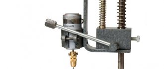
In multi-saw machines, special saws are used, the blades of which have several more cutting edges - flat knives - built into them. Their task is to plan the surface obtained after cutting and prevent the tool from being clamped by the workpiece. In machines with the specified cutting pattern (Fig. 1) there are no riving knives. The use of such saws gives excellent results: the surface quality has low roughness, and the feed speed is allowed up to 20 - 50 m/min. Sometimes, including to compensate for the low quality of the tool, a forced supply of an agent such as a cutting fluid (coolant) is used into the cutting zone. The effect of such a technique is quite controversial, especially considering that in low-temperature operating conditions, when using, as a rule, ordinary water, the effect can be the most unpredictable and detrimental to the equipment.
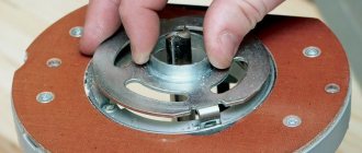
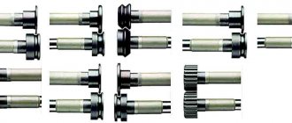
Together with the saws, spacer bushings are installed on the shaft (Fig. 7). Their height a is calculated based on the dimensions of the tool and the sawn timber.
a = C Azuba − Apili,
where C is the size of the resulting timber after sawing (Fig. 1). For a board, this is its thickness; Azuba, Apily - the thickness, respectively, of the tooth and the saw itself.
Special requirements are imposed on the manufacture of spacers for twin-shaft multi-rip machines. The difference in their heights a11, a12, etc. (Fig. 7), as well as the displacement of the base flanges of the shafts Δf leads to a total error Δ in the form of a relative displacement of the saw blades. In practice, this leads to the formation of a stepped protrusion on the surface of the resulting lumber. To avoid defects at the stage of manufacturing spacers, it is necessary to reduce the difference in heights of spacers in a group to 0.1 - 0.05 mm. Torsion from the shaft to the saw blades is transmitted through one or two parallel keys.
One way or another, the first thing to do to avoid stopping the workpiece and jamming the tool is to reduce the feed speed. Regardless of the type of feeder, a system with smooth adjustment of this parameter will be advantageous, followed by a stepwise one with remote control. Changing the speed by changing pulleys is the least preferable.
The geometry of the machine in relation to the task of obtaining high quality products is expressed in the relative position of the saw shafts, pressure and feed rollers, as well as the conveyor in the chain feed mechanisms. If at least one of the drive rollers (Fig. 5) is deployed, then a change in the feed force inevitably occurs, at which the workpiece can rotate. The result is curvature of the resulting board. Moreover, with a board length of 4 - 6 m, even a slight shift of 1° leads to a deviation from straightness of 100 mm (!).
About other machines: polyurethane rollers for the VHold machine
Correcting this situation is not easy, since the developer rarely leaves the possibility of additional adjustment of the position of the nodes. The upper rollers must also move in a vertical position and press the workpiece. And the discrepancy between the plane of the tool and the feed direction leads to jamming of the saw, friction and the same increased energy consumption of the machine. Along the way, it should be noted that it is very preferable to have mechanization of auxiliary movements in the machine - raising and lowering the rollers. In addition to reducing purely physical stress, this option in the form of, for example, a hydraulic cylinder makes the machine capable of adapting to an automated line with automatic adjustment “to size”.
Another common defect, but already associated with the sawn workpiece. If the upper layer is not parallel to the lower one - the base one or has waviness, then the contact patch (Fig. 6) of the upper roller with the wood will most likely decrease and shift. Following this, unbalanced components of forces arise and, accordingly, the workpiece also deviates from the rectilinear trajectory of movement. If in the previous case it was enough to adjust the machine itself, here the task is broader and extends to the selection of related equipment.
Thus, the use of even used sawmills of the R-63 type gives excellent results when paired with any high-quality multi-saw machine only due to the strict parallelism of the specified surfaces of the resulting timber. And, on the contrary, producing a semi-finished product on new-fangled, home-assembled units using narrow band saws leads to the fact that a normally adjusted second-row machine produces a forced curvature of the board due to a defect in the base of the workpiece.
Continuing the topic of machine tool equipment, one cannot help but mention the influence of the method of orientation of the workpiece at the initial moment of the cycle. In most cases, double-edged timber obtained at the first row sawmill is sawn. Since it does not have a reliable lateral base surface, it is manually centered relative to the machine on the input table or roller table. If the workpiece receives an initial angular displacement, then the percentage of finished product yield sharply decreases (Fig. 8a). Special devices - optical cut line indicators - are designed to reduce the risk of defects.
About other machines: Safety precautions when working on a sheet bending machine, General safety requirements - Life safety in metal bending production
But the greatest accuracy is provided by the technology of cutting three- or four-edged timber. The workpiece is pressed by the side base surface against the guide ruler (Fig. 8b). The ruler is located at a given distance from the outer saw, so the first board is of a given thickness. In addition to accuracy, workpiece positioning also makes a significant contribution to machine productivity.
If we theoretically imagine that a semi-finished product with a cross-section of 400 x 200 mm is fed into the machine continuously at a speed of 20 m/min, then the processing volume can reach 700 m3 or more in an eight-hour work shift. The indicator is impressive, as is the fact that it is due to downtime that this value is reduced to the level of 100-200 m3. That is why the integrated organization of the production process is so important.
The design of the saw shafts also has an impact on productivity. The significant difference between the maximum dimensions of workpiece A and tool set B (Fig. 1) leads to the fact that only 50% of the workpiece is sawn in one pass. Additional return transport flows are forced to be organized, along which the uncut part again reaches the input roller conveyor of the multi-saw machine. The fact is that the saw shaft with a length of working part B of up to 300 - 350 mm is made in the form of a console. This design allows for easy tool replacement.
Multi-saw machines are highly dangerous equipment. Developers are striving to introduce more and more advanced safety systems, such as a two-way anti-blowout system that prevents the timber from moving backward during the sawing process. The kinetic energy of massive workpieces and rotating tools moving at high speed is very high, and therefore the issues of safe organization of work in such areas are of paramount importance.
Stationary machine with your own hands
To perform everyday or one-time tasks, a hand-made circular saw is quite suitable. Small-volume sawing work does not imply heavy loads on the disk drive. The compact tool has small dimensions, which makes it possible to put it away after finishing work in a certain place. An experienced carpenter will need to make a large stationary type circular saw.
Circulation table
The main condition for making a table is the selected material. It is recommended to use a solid steel sheet, duralumin or silumin alloy. Materials such as moisture-resistant plywood, plexiglass and textolite require processing and installation on top of a galvanized sheet. The use of any material in manufacturing must meet the main conditions:
- increased vibration resistance;
- sagging with a load exceeding 50-60 kg is unacceptable;
- the presence of a perfectly flat surface.
In cases where the conditions are not met, a DIY circular saw may stop due to a jammed disk or a broken drive. The consequences can be different, from a damaged part to injury to a person.
There are several options for making a circular table. Stationary tables can be sawed or made from two parts. The circular saw blade should protrude no more than a third of its diameter.
Saw blade
Saw blade
The design of a DIY circular saw must contain a saw blade. The working surface of the disk is set to one third of the total diameter. For example, with a diameter of 210 mm, the disk should protrude 70 mm from the table. Parts with greater thickness will require a powerful motor, from 1 kW. A miniature circular saw will not cope with such tasks.
The splitting knife installed on some models serves to prevent short circuits and jamming during operation. It is located at the back a few millimeters from the teeth of the saw blade. The device may also be needed when making a circular saw with your own hands.
Adjustable side support
Any type of work will require a stop. The side support is made of a block of dense wood. In other cases, it is possible to make it from a metal corner. The arrangement should be slightly longer than the table structure. The stop is installed using bolts. The template is installed between the table and the cutter for precise installation and better settings.
Shaft
Homemade shaft
The most important part of the design is the shaft mounted on the circular saw. A self-made shaft for a circular saw can damage the structure and cause injury. The reason for this is runout, which cannot be avoided when making a shaft using artisanal methods. The manufacture of the shaft should be entrusted to a specialist with good turning equipment. You should remember that there is a cutter that needs a seat. The holes must be symmetrically machined and machined.
Finished shafts are sold in specialized markets. Preference should be given to parts with a self-aligning bearing. Otherwise, the conventional mechanism may soon render the circular machine unusable.
Broadcast
There are several types of gears that can be used in the design of a DIY circular saw:
- V-belt transmission;
- mechanism consisting of gears.
The preferred option is to use a belt drive. Using a mechanism with gears can lead to jamming if a foreign body enters and injury to the worker. When choosing the pulley diameter, the maximum number of revolutions of the saw blade is taken into account.
Motor
Electric motor for circular saw
In most cases, homemade machines are equipped with an engine from an old washing machine. The main features are increased service life and efficiency. The speed of such engines is not high, which makes working on a circular saw assembled with your own hands safer, longer, and has a positive effect on the result. The use of a special three-phase motor implies the presence of a 380 Volt network. If one is not available, you will have to use a starting and running capacitor, which leads to additional costs.
Production Features
The technology for manufacturing peeled veneer has been known since the beginning of the 19th century, and over the years, the equipment used for the production of veneer has undergone many design changes and technical changes. However, the basic principles remain unchanged.
Churak, or in other words, the workpiece, which has previously been dried, is fed to a special peeling machine. The size of the block, length and diameter, depend on the model of the machine and its technical characteristics.
When the workpiece is fed to the machine, it is fixed in spindles, devices installed at the ends of the block.
An important point when installing a workpiece is correct alignment, because otherwise, during the next operation, rounding, there will be a large percentage of wood waste.
Rounding is a technological operation when, when rotating a block, sections of wood and its unevenness are removed from its surface. Removal is carried out until the workpiece is given the appearance of a correct cylinder.
After the cylinder is formed, the peeling process begins.
In this mode, simultaneously with the rotation of the block, the cutting knife moves in the direction of the center of rotation, which leads to cutting off a layer of wood of the required thickness.
The cut wood sheet (veneer) is wound on a special device (reel), located next to the peeling machine, or cut to the required size.
Distinctive features of the production of peeled veneer on an industrial scale are:
- the need to prepare blanks used for the production of veneer (hydrothermal treatment, heat treatment);
- sorting workpieces by diameter and length (crosscutting);
- sorting of assortments by types of raw materials and quality.
Original devices
The list of homemade products can be continued endlessly, but we’d rather talk in more detail about some homemade machines that can be made from any model of drill.
Drill
A drill made from a drill is not a fantasy, but a real and fairly universal machine, assembled independently. The main thing is that you need to order from Chinese engineers (if you couldn’t find it in your city) a flexible shaft from a standard medical unit. As a result, a drill appears in your arsenal, which can be used for engraving work or drill holes using special burs in small parts or structures that cannot be reached with a standard drill.
Lathe
A woodworking or lathe for home can easily be made using a drill. The tool must be secured with special clamps quite firmly, and a specially designed holder with several sharp pins must be inserted into the chuck to keep the workpiece from turning. The center of the rear holder (headstock) and the clamp at the front of a homemade lathe should be located on the same axis. Precision is necessary to prevent runout as the workpiece rotates. After installing the part, the tailstock is firmly fixed with a special clamp.
The third element of the machine is a tool rest in the form of a wooden block on which a chisel or other tool for processing the workpiece will rest.
A lathe for processing wooden workpieces will work properly if the drill has a built-in electronic speed controller. Using the trial method, you establish the optimal rotation mode for effective wood processing. Using such a woodworking device, you can make unique products for household needs: for example, a rolling pin or pestle with a mortar, a candlestick or a prefabricated candelabra.
Winch
An original winch based on an old but powerful drill will become an indispensable assistant in the household, especially for those users who live in their own home and have a personal plot. A simple situation: you decided to install a larger container in your summer shower, but raising it to such a height alone is problematic. Using a winch, this can be done in a few minutes. You just need to first calculate the weight of the container and the spindle speed.
According to garage craftsmen, a homemade winch can easily lift the engine from a passenger car. Watch the video if you don't take my word for it:
Experts advise using a homemade device, setting the drill at the lowest speed. This design can move objects with different masses, because craftsmen even make winches based on an ordinary car starter.
Electrical part
It is better to do the electrical wiring from a familiar technician, or contact a professional electrician, than to do it yourself. Often it is the wiring that fails at the most inopportune moment. It is worth noting that, as a rule, when working with wood, piles of sawdust are formed around the machine, which are easily flammable, so it is better to entrust the power supply to the machine to a professional.
Installing the working area on the frame with your own hands does not require any special skills. The hardest part is: marking the cuts. To do this, take cardboard according to the size of your future desktop, cut out an oblong hole in the place where it rests on the cutting element. The hole is located in such a way that when rotating the disk does not scratch the cardboard and is at least 3 mm from the edge of the workpiece. We retreat to the right side 5 mm, and draw a perpendicular line and outline a contour 7 mm thick around it. Thus, we designate the adjustment slot of the guide die.
Special protection for hands
Having cut out a strip of 5 mm metal, the width of the working plane, and a height of 50 mm, we weld two bolts with a diameter of 12 mm symmetrically to the center. With these bolts we will regulate the movement and displacement of the thrust guide bar of the working surface.
We cut out all the necessary slots using the cardboard blank, install the guide die and weld it directly to the frame.
After installing all the equipment, you need to connect the sawing machine to the network with your own hands and check the correct rotation of the circle. The circle should rotate clockwise (towards the board).
It is best to make the first start remotely using a long carry and a circuit breaker.
After checking, it is necessary to test the power capabilities of the unit. There are several ways to do this.
Machines for the production of veneer - features, types, application and purpose
Expensive varieties of timber are excellent raw materials for creating furniture, but not all people can afford such expensive products.
In order to save valuable types of wood and reduce the cost of the final product, veneer was invented. This material is extremely popular today for cladding furniture.
Veneer 100% repeats the pattern, texture and shade of natural wood.
To create veneer, factories use special machines. Veneer can be:
Accordingly, there are three types of veneer production machine.
How to make a jointer tool
The jointer has a simple design, it can be made in a few hours: the process does not require special skills and knowledge. A power planer is useful in carpentry, but the quality of wood processing is inferior to a jointer. Therefore, it is necessary to improve the existing sample to achieve a better result.
An electric planer with a sliding blade guard that can be retracted during jointing is well suited as the main element of future equipment. It is better if the plane is equipped with a fastening with knives facing upwards.
During the assembly process you will need:
- boards,
- plywood sheet,
- fasteners.
Step-by-step instruction
First you need to make a base of boards. It should have the shape of a box without a bottom or lid. The length of the frame will correspond to the length of the working surface.
At the next stage, a sheet of plywood must be laid on top of the box, a technological hole must be formed, and the plane platform will be installed in it.
Two more similar sheets are laid on top of the plywood, serving as the back and front plates. The sheet that the tree will accept when planing should be 2 mm thicker. It is necessary to maintain parallel placement of plywood sheets. This can be verified with a sliver probe. Before fixing the panel to the frame, the edge of the material is processed .
The hand-held electric planer fits onto a mount mounted with the knives facing up on the bottom sheet of plywood.
You will need wood to cut out the mounting lugs. Adjusting bolts will be threaded through these elements, setting the machine knife to a given height relative to its base.
You need to install a side stop made of the remaining plywood on the jointer . After this, you can begin processing lumber.
Alternative option
If you don’t plan to work with long workpieces, you can make a compact household device. This circular saw can be easily equipped with special supports and turns into a full-fledged machine.
First you need to form a box from thick plywood, wood or MDF. The structure is fixed with wood glue or reinforced with self-tapping screws. The role of the countertop is performed by the electric planer platform.
The most complex element that a jointer is equipped with is a side stop . It will move on special grooves.
Its fixation is ensured by two screws and wing nuts. The cutting tool is held in the box by side fasteners.
For convenience, a home electric jointer can be improved by forming in its design an outlet for connecting an industrial vacuum cleaner.
We assemble the machine with our own hands
To assemble the machine with your own hands, you need to make a drawing indicating all dimensions and perform a number of works. For use at home, a small compact device, equipped with as many functions as possible, is more convenient.
A pre-prepared drawing will help you avoid mistakes that are often made when making a planing machine yourself.
To make a planing machine with your own hands, you may need the following components:
- electric plane;
- pulleys;
- electric motor;
- drive unit;
- Control block;
- working shaft with cutters;
- wiring;
- sheet metal 3 mm;
- corner, pipes;
- plywood 10-15 mm;
- planed boards;
- a set of mounting bolts and nuts;
- self-tapping screws
You can make a homemade machine with your own hands using 2 design options (drawing):
- based on an electric planer;
- according to the traditional scheme (the shaft is driven by an electric motor).
It is first necessary to develop a drawing for each scheme and make a final decision, taking into account the advantages and availability of components for assembling a planing machine with your own hands.
We carry out work on the manufacture of individual parts and assembly of equipment (according to the drawing):
- We make a frame that can be assembled from metal pipes, connecting individual parts by welding or from wooden blocks, in compliance with the requirements for structural strength.
- On top of the bed we install a work table made of plywood with a cut for mounting a plane.
- We install additional 2 sheets of plywood, which will serve as limiting plates - front and back.
- We install the electric planer with the knife facing up and firmly fix it.
- We fasten the mounting bolts with devices for adjusting the position of the electric planer relative to the working surface of the table.
- We install an adjusting stop made of plywood.
Purpose of multi-rip machines
The functions of the machines are very different. They can produce boards from a two- and three-edged carriage, cut timber into smaller boards, produce a board from a slab, then the saws in the machine are not only longitudinal, but also transverse.
Most people use a multi-saw after cutting the log down to a two-edge beam with a band sawmill. Models differ in the number of saws, band or disk. The maximum number of installed disks is 24 pieces.
When choosing, take into account the power and weight of the unit. Large productive machines can weigh more than one ton, and a concrete foundation will be needed so that the tool stands level and does not vibrate during operation.
Traditionally, wood sawing machines have a single saw blade. If the operation of cutting material into pieces of equal width is performed many times a day, you should think about buying a multi-saw. It has better performance.
Flaws
The choice of one or another type of veneer is influenced by the presence of disadvantages inherent in each of the materials being compared.
Thus, peeled veneer has the following disadvantages:
- large losses of wood associated with the preparation (rounding) of blanks;
- the veneer texture has an uneven and non-repeating structure with wide veins;
- the right side of the veneer turns out to be uneven and torn, which is due to the production technology.
Veneer peeling is a technology that makes it possible to produce various types of building materials at low cost for various types of construction and installation work.
| Lumber for construction: making chipboard, making fiberboard, how to make joinery boards, plywood, veneer) |
Peeled veneer - what is it?
Veneer is a building material consisting of flat, thin sheets of wood of varying thicknesses.
Depending on the equipment used and production technology, veneer is produced with a thickness of 0.1 - 10.0 mm, and in accordance with the production method, it is classified as: sawn, planed and peeled.
Peeled veneer is produced on special equipment, peeling machines, the principle of which is based on cutting layers of wood of a given thickness from a cylindrical blank rotating around its axis.
Various tree species are used to produce peeled veneer: birch, aspen, alder, beech, maple, linden, poplar, spruce, pine, larch, fir and cedar. It is used for the production of plywood and other board building materials (carpentry, plywood boards, etc.), for the manufacture and cladding of furniture.
Depending on the quality of the wood used, its species, as well as the quality of processing, depending on the type of equipment used, peeled veneer is divided into five grades, these are:
- E (elite), I, II, III, IV – for hardwood;
- Ex (elite), Iх, IIх, IIIx, IVx – for coniferous trees.
The document regulating the production of peeled veneer is GOST 99-96 “Rolled veneer. Technical conditions".
Currently, a new document has been developed, in accordance with which this building material will be produced in the near future, this is the Interstate standard “GOST 99-2016 Peeled veneer. Technical conditions”, which is currently being approved by regulatory organizations.
Machine design
All of these devices have certain basic parts:
- Bed - includes all components of the device, may also include a lumber supply line.
- Power unit - creates a rotational or reciprocating motion of the saws processing the material. It also drives the workpiece feed unit.
- Sawing mechanism - consists of one or more shafts on which saw blades are installed. The shafts can be in a horizontal or vertical plane.
- The mechanism responsible for feeding the workpiece. The larger the feedstock, the more powerful this unit should be. It is responsible for uniform transportation of the carriage or timber. The accuracy and evenness of the saw depends on this element.
Do-it-yourself peeling machine – Machine tools, welding, metalworking
Expensive varieties of timber are excellent raw materials for creating furniture, but not all people can afford such expensive products. In order to save valuable types of wood and reduce the cost of the final product, veneer was invented. This material is extremely popular today for cladding furniture. Veneer 100% repeats the pattern, texture and shade of natural wood.
To create veneer, factories use special machines. Veneer can be:
- peeled
- planed
- sawn
Accordingly, there are three types of veneer production machine.
How plywood is made: preparing logs, rounding and peeling, cutting into sheets, drying in a press, trimming, sorting and storing
All photos from the article
The topic of this article is making plywood. We will get acquainted with the full cycle of its production - from debarking tree trunks to shipping the finished material to the warehouse. In addition, we will find out whether it is possible to produce plywood at home.
One of the stages of production is feeding the logs into the peeling machine.
Production cycle
It consists of several stages:
| Stage | Works |
| 1 | Debarking and cutting the trunk into logs of equal length |
| 2 | Log rounding and veneer peeling |
| 3 | Cutting veneer into sheets and passing them through glue rollers |
| 4 | Gluing sheets in a press |
| 5 | Trimming edges |
| 6 | Sorted by surface and edge quality |
| 7 | Shipment to warehouse |
At some stages it is worth going into a little more detail.
Technical specifications
Among the main technical parameters of multi-rip machines, it is worth highlighting:
- workpiece sizes. The maximum size of raw materials that can be processed determines the permissible dimensions of the workpieces
- number of installed saws. This parameter shows the largest amount of timber per run
- Feed speed affects the productivity level of the machine
- workpiece cutting speed
- saw diameter characterizes the depth of cut
- the largest distance between the saws is responsible for the width of the final timber
- power indicator
- dimensions of the equipment itself
- weight.
Taking these parameters into account will help you select a machine for the volume of work you need, operating conditions and production purposes.
Multi-saw machine design
Regardless of the type, this equipment has a stable and heavy frame that holds all the elements of the device and the workpiece feeding mechanism, a power unit responsible for creating rotational or reciprocating forces, and shafts with saws fixed in a horizontal or vertical plane. Accordingly, the larger and denser the initial raw material, the more powerful the components of the machine and its engines should be; models are powered primarily from a three-phase network.
The most functional varieties have the ability to adjust the width of the stand (the distance between the saws), are equipped with CNC units or control the material feed speed. The latter allows you to process wood blanks with different densities and dryness with the same precision; the smoother this characteristic changes, the better. Budget multi-rip machines do not have this option or do it in stages.
Features of operation
Despite their unpretentiousness, multi-rip machines require compliance with certain maintenance rules; in order to reduce defects and extend their service life, it is recommended:
- It is recommended to control the feeding speed of workpieces or logs depending on the material parameters and loads; it is recommended to feed denser and greener wood slowly.
- Adjust the machine when defects appear, monitor the sharpness of saw sharpening and promptly change cracked or worn out tools.
- Clean equipment from chips and dust after work.
- Lubricate working units at the intervals specified in the instructions for the unit, and comply with other manual requirements.
- Carry out systematic equipment diagnostics. The feed line requires special attention; its rollers or rollers must be in perfect condition; deviation can lead to a violation of the geometric accuracy of the parts produced by the machine and failure of the entire line.
Peeling of veneer
Peeling of veneer is a process of cutting wood, when the block is given a rotational movement, and the cutting tool is given a translational movement in the direction of the axis of rotation of the block. The process of obtaining a thin tape is similar to unwinding a roll of paper (Fig. 4). The cutting speed is a variable value, since the number of revolutions of the block is constant, and the diameter of the block decreases during the peeling process. The block is clamped between the machine spindles by moving them axially. The rotational movement of the spindles is obtained from an electric motor. The knife is mounted on a support, the movement of which is carried out using a feed mechanism. The maximum length of the processed block (the width of the veneer strip) depends on the distance between the clamping jaws. For modern machines it is within 500...5000 mm. The largest diameter of the processed blocks depends on the height of the centers of the spindles above the bed. In modern machines it is 400...2000 mm.
Rice. 4. Churak peeling scheme
After peeling the block, waste remains in the form of a cylinder, called a pencil, the diameter of which depends on the diameter of the clamping jaws. To reduce the diameter of the pencil, the cams are made telescopic. At the beginning of the peeling process, the block is clamped with external cams having a diameter of 100...110 mm, and then at the end of the process the clamping is carried out with internal cams with a diameter of 55...65 mm.
The veneer thickness is the amount of knife feed per spindle revolution. In the latest models of machines, the thickness range can be within 0.05...5 mm.
When cutting wood freely, cracks and irregularities appear on the left side of the veneer facing the block.
To eliminate them, veneer is crimped using a pressure ruler, which is installed so that the pressure it creates is directed through the cutting edge of the knife. In this case, the gap between the knife and the ruler must be no less than the calculated thickness of the veneer. The degree of compression (Δ,%) can be determined by the formula:
, (4)
where S is the estimated veneer thickness, mm; S0 – distance between the knife and the pressure ruler, mm.
To ensure the required quality of veneer, the degree of crimping must be maintained within 10...30% depending on the type of wood, veneer thickness and block temperature.
When peeling the block, four zones are distinguished (Fig. 5):
The volume of wood in each zone can be characterized by the following figures: flaw zone - 20...23%; zone of long pieces – 4…5%; full-length veneer zone – 57...59%; pencil zone – 15...17%.
Rice. 5. Peeling zones of the block: 1 – flaw zone, which is a consequence of the irregular shape of the block; 2 - zone of long pieces, which is a consequence of incorrect installation of the block between the machine spindles; 3 - zone of full-length veneer; 4 – pencil zone
In the case of peeling wood on a machine equipped with a centering device, the useful yield (q, m3) can be determined by the formula:
(5)
where dch is the diameter of the block, m; dк – pencil diameter, m; lch – block length, m; Kv – coefficient of yield of raw veneer from the block.
The volume of block remaining after peeling (qh, m3) is determined by the formula:
(6)
The volume of a flaw from one block (Q, m3) is determined by the formula:
(7)
where qch is the volume of the block, m3.
The veneer yield is expressed as a percentage of the volume of the block:
(8)
Lump veneer, formed in the initial stage of peeling, is used for the manufacture of small-size plywood or the cores of full-size plywood. The minimum length of selected pieces is 0.8 m, the minimum width is 0.13 m. Proper organization of the selection of pieces increases the veneer yield by 4...4.5%. Currently, the most widely used peeling machines are the brands LU 17-4, LU 17-10, SL-800, SL-1600 (Russia) (Fig. 6); SF 2350 (Italy); Tokyo Pleetwood MK (Japan); MQW2314/35B2 (China).
Rice. 6. Peeling machine SL-1600
The veneer obtained by peeling a block has the form of a strip, the width of which is equal to the length of the block, and the length depends on the diameter of the block and the thickness of the veneer.
At the exit from the peeling machine, the veneer strip is cut into separate strips, the width of which is determined from the expression:
(9)
where Vf is the width of the finished plywood sheet, mm; Δ0 – allowance for cutting (75…80) mm; Δу – allowance for shrinkage depending on the type of wood and sheet size, mm.
DIY sawmill with a gasoline engine
In the process of choosing equipment intended for wood processing, it is also necessary to take into account the high cost of the tool itself. It is for this reason that few consumers can afford to buy a sawmill. But as we said earlier, anyone can make this kind of tool themselves.
Homemade sawmill with a gasoline engine
At this point you can learn how to make homemade circular sawmills with your own hands with a gasoline engine. We will also take a look at a homemade circular sawmill driven by a PTO. So, let's begin to consider this issue.
First of all, what you should stock up on is patience and a great desire to acquire this kind of device.
In order to actually begin this process, first prepare drawings for a homemade circular sawmill (can be obtained on the Internet), and also prepare construction sawhorses, metal plates, boards, screws, screws, nuts, a special tool with the use of which you can work with wood and metal, as well as the gasoline engine itself. So, let's get started.
- First, you need to obtain all the necessary information regarding the device of this tool itself, in order to have the opportunity and understanding of what and how you should produce.
- In addition, there is another option, which has the saw itself mounted on the motor shaft. On the very surface of the sawmill, processing of the so-called sawlog begins, which actually divides the unedged board. You also need to cut special blanks, each of which must meet the required size.
- It is worth noting that the simplest design of this process is the table. It is under its lower part that you must actually place the shaft itself with the saw mounted on it. The cutting part with which it is equipped should rise, so to speak, on the table surface itself. the movement of the saw shaft is produced by the action of a gasoline engine on it, which transmits peculiar impulses to the belt itself.
- Actually, the discs themselves for this kind of sawmill will serve best if they are made of duralumin or steel sheets. And its actual size should correspond to three millimeters. And the actual diameter should be 500 mm. It is important that if you are making a device in order to subsequently cut wood, then in this case you will need a disc with two or three teeth. Since this is the best option for this type of work.
- It is worth noting that the basis for the high level of sawmill production is the very manufacture of these teeth. In addition, the most important thing is that you carefully carry out the balancing and determine the correct cutting angle.
In the video you can watch how to do this:
Peeling machine
At first glance, plywood seems to be one of the first candidates for the production of pohadets. After all, everyone knows how to make plywood! Here is a cylinder of wood (block), a knife is attached to it, the block spins and sheets of veneer carefully come off it, from which you can glue a lot of useful things, from Roman shields to airplane bodies (in the First World War, some airplanes were glued from veneer in concrete forms - in halves, gluing the sheets with banal animal glue and pressing them with sandbags).
And a logical question arises: why then did real plywood appear only at the end of the 19th century?!
My favorite childhood memories are visits to my grandfather in the carpentry workshop. Mountains of incredibly delicious-smelling shavings, higher than the roofs of buildings. I took it and admired the healthy turns of wooden spirals, covered with notches on the outside...
The problem is that when the knife cuts the chips freely, they immediately break. If you plan wood along the grain, then at certain angles you can peel off veneer sheets without damaging them, because the wood along the grain is strong enough and can withstand bending to allow a knife to pass between the bulk of the workpiece and the veneer sheet. However, the peeler must cut across the grain.
Alas, when cutting transversely, the removed veneer sheet will immediately break, without leaving the cash register. Probably the most striking example of this phenomenon will be sharpening a pencil in a sharpener - the curls of wood coming out of it crumble into powder, and not only because the cut is not parallel to the grain.
When cutting a layer of wood from the surface of a rotating cylindrical body and straightening the latter, internal stresses arise in it: compression on the front side and tension on the back side. Since the tensile strength of wood across the grain is relatively low, during free cutting a leading crack is formed in front of the cutting edge of the knife, the direction of propagation of which is arbitrary; large micro-irregularities will inevitably appear on the surface of the veneer (protrusions on the back side, depressions on the front side).
Thus, if you peel only with a knife, it is impossible to obtain high-quality veneer.
The way out of this situation is to compress the wood in the zone where the knife is inserted into it, which is achieved by a special clamping element installed near the knife at a distance less than the thickness of the veneer (i.e., feeding the caliper per turn of the block). It creates a compression zone extending radially into the depths of the block. The compaction of wood in the immediate vicinity of the pressing element reaches 30-40%. When a knife cuts a layer of wood and passes it between the front edge of the knife and the pressing member, the layer is compressed in the radial direction.
Then a very difficult task begins - to ensure accurate supply of the clamping element (this can be either a wedge-shaped metal plate or a cylinder, and the cylinder, despite the rolling friction, requires great effort to clamp). And the exact location of the clamping element relative to the knife. All these parameters must either be calculated using long-established formulas, or explored from scratch yourself.
Another problem is the precise choice of cutting angle. And it changes, infection, with a decrease in the diameter of the block. To compensate for this, peeling machines have not only a horizontal feed, but also a mechanism for changing the tilt of the knife.
Making a homemade sawmill
Before manufacturing the installation, detailed drawings of all components included in the design of the unit should be drawn. The simplest installation option is a single-disc sawmill. The scheme of such a design includes the following elements:
- moving carriage;
- two electric drives.
One of the electric drives ensures the movement of the portal along the guides, and the second drive serves to move the circular saw.
Sawmill assembly diagram.
This design is called horizontal. The device carriage is made of metal; it should easily move on rollers along the installation guides.
Making equipment with your own hands begins with preparing tools and materials for construction, these are:
- construction trestles;
- boards;
- metal plates;
- elements;
- electric motors;
- a set of tools and accessories for assembling the unit.
To manufacture the unit, you first need to assemble the frame of the device. For this purpose, construction trestles are combined using boards. The length of the boards used depends on the size of the material that is supposed to be processed on a homemade machine.
After making the frame, proceed to the plane of the table. Its base is made of wood, and metal plates with a width of 230-250 mm and a thickness of 1.2 mm are fixed to the surface. The plates are connected to each other by jumpers and screws. After making the table, a groove is made in its wooden part in such a way that the installed circular saw does not come into contact with its edges.
You can make a cutting tool yourself, but it is best to purchase it at a hardware store. The disk is fixed on a shaft, the drive of which is carried out using a belt drive. When securing the engine, it should be possible to move it slightly, which is necessary to tension the belt drive. The guide for the sawmill is made of boards.
Pereosnastka.ru
Design of peeling machines
TO
category:
Production of plywood
Design of peeling machines
Peeling machines are divided according to technical indicators: - according to the greatest distance between the centers of the spindles. This distance determines the maximum possible length of the knife and the length of the logs to be peeled.
The most common are machines for peeling logs with lengths of 1350, 1650, 1950 mm. The length of the block is determined by the size of the veneer sheets;
- according to the height of the centers of the spindles above the bed.
The height of the centers is determined by the largest radius of the block with an allowance of 100-150 mm.
Domestic machines are designed for peeling raw materials with a diameter of 60-70 cm. Foreign companies produce machines for peeling logs with a diameter of more than 80 cm.
The LU-17-4 peeling machine consists of the following main parts: a frame, two spindle heads, a kinematic unit support, a pressing mechanism, and a centering and loading device.
The machine bed is used to fasten all the main parts of the machine, to absorb dynamic cutting loads and auxiliary peeling operations.
The bed is a rigid welded frame made of I-beams, on which cast-iron spindle heads are installed. There is a slot in the frame for throwing the pencil down onto the conveyor.
The spindle headstocks (right and left) serve to secure the block and give it rotational movement.
In Fig. Figure 2 shows a section of the right spindle head. The spindle head has two telescopic spindles with corresponding cams.
The presence of a large cam allows you to avoid splitting of blocks during the initial period of peeling, and a small cam makes it possible to peel a pencil with a diameter of up to 70 mm.
Clamp the block on the machine as follows.
Rice. 1. Machine LU-17-4: 1 - bed, 2 - left spindle headstock, 3 - centering and loading device, 4 - welded beam, 5 - pressure rollers, 6 - right spindle headstock, 7 - block clamping mechanism, 8 - hydraulic drive, 9 - hollow shaft, 10 - cast iron beam, 11 - caliper, 12 - drive for accelerated movement of the caliper, 13 - electric motor, 14 - block feeding mechanism
The pump supplies oil from the hydraulic system to the distributor. The piston under pressure moves the rod in a large hydraulic cylinder up to 150 mm.
The piston rod, rigidly connected to the movable bearing assembly of the small spindle, also moves along the length of the hydraulic cylinder. The small spindle is secured to the small spindle bearing assembly.
The latter, moving freely inside the hollow large spindle, clamps the block with its cam.
Rice. 2.
Section of the right spindle head of the LU-17-4 machine: 1 - piston, 2 - large hydraulic cylinder, 3 - piston rod, 4 - movable bearing assembly of the small spindle, 5 - housing, 6 - spline bushing, 7 - gear key, 8 - gear, 9 - sprocket key, 10 - sprocket, 11 - rotor, 12 - hollow large spindle, 13 - small cam, 14 - large cam, 15 - small spindle, 16 - spherical roller bearings, 17 - splined bushing of the large spindle, 18 - lever, 19 - movable bearing assembly of the large spindle, 20 - splines, 21 - key, 22 - sliding keys, 23 - small hydraulic cylinder, 24 - small piston with rod, 25 - pin
Oil simultaneously enters the large and small hydraulic cylinders. The small piston with the rod moves towards the block and, acting on the lever, displaces the movable bearing assembly of the large spindle.
The amount of displacement of the small piston with the rod depends on the size of the small hydraulic cylinder and is 150 mm.
A hollow large spindle fixed in a movable bearing assembly moves by a specified amount and clamps the block with a large cam.
Thus, two spindles simultaneously clamp the block with cams attached to them. The operation of the left spindle is similar to that of the right one.
After clamping, the block is given a rotational movement from the main shaft through the gear. The rotating gear, through a key, rotates the sleeve, which, with the help of a splined sleeve 6, rotates the large hollow spindle. The large spindle rotates the small spindle through the spline bushing of the large spindle.
Sliding keys protect movable bearing units from rotation; at the same time they act as guides for the horizontal movement of these units.
During the peeling process, when the peeling knife approaches the rotating cam of the large spindle, the hydraulic system returns the large spindle to the starting position. The same thing happens when the peeling knife approaches the cams of the small spindle.
The system for supplying oil to the hydraulic cylinders to return the spindles to their original position was shown in Fig. 1.
The hydraulic system is connected to the spindle heads in such a way that when oil is supplied to the pistons of the large and small hydraulic cylinders, these pistons return to their original position. Thanks to the hollow design of the large spindle and the spline connection of the two spindles, their independent movement relative to each other in the horizontal plane is achieved.
Thanks to the use of spindle heads, it became possible to peel blocks with a diameter of up to 70 mm on the LU-17-4 machine, abandoning the use of small peeling machines for this operation.
The support of the peeling machine is designed to secure the knife, adjust it, configure it, and to give it a reciprocating movement (to the block and back).
The support consists of two side sliders moving along horizontal removable parallels located on the machine bed; knife traverse - for attaching and adjusting the peeling knife; crossbars of the clamping ruler - for fastening and adjusting the clamping ruler of the machine; two caliper screws that impart reciprocating movement to the caliper.
The support has additional upper and lower guides, with which the knife traverse is connected and with the help of which the cutting angle is changed during peeling of logs. The pressure ruler is connected to the knife crossbar by an eccentric shaft.
The block pressing mechanism eliminates the deflection of the block at the end of peeling under the influence of cutting forces.
This mechanism consists of a cast iron beam mounted on a hollow shaft, two pairs of pressure rollers, a hydraulic cylinder for moving the rollers mounted on a welded steel beam connecting both headstocks of the machine, as well as a device for adjusting the synchronization of the movement of the knife and pressure rollers. The pressure roller block is pivotally connected to the beam and to the hydraulic cylinder rod. The journals of the hollow shaft are installed in bearings, the housings of which are attached to the headstocks of the machine.
The kinematic unit of the machine serves to connect the working parts of the machine (support and spindle heads) and give them working movements.
In Fig. Figure 3 shows a kinematic diagram of the LU-17-4 peeling machine. A block centered and clamped in the spindles of the machine (the operation of the centering and loading device will be described below) is driven into rotation from the main shaft through gears. The main shaft is connected to the electric motor through a V-belt drive and an electromagnetic clutch.
Rice. 3.
Kinematic diagram of the LU-17-4 peeling machine: 1 - main electric motor, 2 and 22 - V-belt drive, 3 - electromagnetic clutch, 4, 5, 6 - gears, 7 - main shaft, 8, 9, 10, 16, 17, 18 - sprockets, 11 - intermediate shaft, 12 - right hollow shaft, 13 - cam clutch, 14 - transmission shaft, 15 - left hollow shaft, 19, 20 - bevel gears, 21 - support shaft, 23 - electric motor for rapid approach and retraction calipers, 24 — caliper screws, 25 — pistons of the hydraulic cylinder of the servo system, 26 — pneumatic cylinders for centering the blocks, 27 — feed mechanism for the blocks, 28 — handle for switching the accelerated and working feed of the caliper, 29 — electromagnet; a, b, c, d - replaceable gears for dialing veneer thicknesses
The left spindle is driven into rotation from the main shaft also through gears. The gear, rotating the sleeve of the right spindle, imparts rotation to the sprocket. The sprocket is connected to the intermediate shaft by a bushing-roller chain through a sprocket rigidly fixed to the intermediate shaft.
The shaft drives the right hollow shaft into rotation through replaceable gears a, b, c and d. Through a cam clutch mounted on a sliding key, rotation from the hollow shaft is transmitted to the transmission shaft.
Through a sprocket rigidly fixed to the shaft and a bushing-roller chain, rotation is transmitted to the support shaft through the sprocket.
A system of bevel gears drives the caliper screws, and the latter drives the caliper, which moves along guides to the rotating block. The translational movement of the caliper is carried out thanks to caliper nuts, rigidly connected to the caliper body.
The amount of caliper feed per block revolution, i.e.
the thickness of the removed veneer depends on the location of replaceable gears a, b, c and d, since a rigid connection in all links of the kinematic circuit, except for replaceable gears a, b, c and d, ensures a constant gear ratio.
The table shows that changing the veneer thickness from 0.2 to 3.2 mm is achieved mainly by changing gear a with the mutual arrangement of the block gears (b - c) in two positions.
Towards the end of peeling, when the diameter of the block approaches the diameter of the small cam of the spindle, the working feed of the caliper stops when the claw clutch is moved to the neutral position with the handle. At the same time, the electromagnetic clutch is removed from the connection with the V-belt pulley and the rotation of the pencil in the machine spindles stops.
Using an electromagnetic clutch, you can stop the movement of the main shaft without turning off the main electric motor, which is economically feasible, since starting torques when turning on the electric motor negatively affect the power supply of the enterprise.
The hydraulic system returns the spindles to their original position, and the pencil is removed from the workshop through a slot in the frame by a conveyor.
By rotating the caliper shaft in the opposite direction relative to the working movement of the electric motor, the caliper is returned to its original position through a V-belt drive.
The caliper is fed to its original position at an accelerated feed, which gives a significant gain in time. After this, the electric motor is turned off. In this position, the peeling machine is ready for peeling the next block.
Then the operation is repeated as described above.
In addition to the working feed, which ensures the production of veneer of a given thickness, the peeling machine has an accelerated feed, which is used in the initial period of peeling to remove large irregularities on the block.
The rapid feed is activated by the left hollow shaft coupling. The rotation of the shaft is transmitted to the shaft through the coupling. Further rotation is transmitted as during working feed. The rotation of shaft 15 is carried out from the shaft by sprockets and a bushing-roller chain.
In this case, the system of replaceable gears a, b, c ig is disabled and does not take part in the work.
After finishing the stripping (at the accelerated feed of the caliper), move the claw coupling with the handle, thereby turning off the shaft and turning on the shaft. Next comes the peeling process at the working feed. The electromagnet serves to automatically move the dog clutch to the neutral position.
Rice. 4. Diagram of the centering and loading device: 1 - freely rotating axis, 2 - pneumatic cylinder, 3 - lever, 4 - load, 5 - upper gear, 6 - sector without teeth, 7 - pincer grips, 8 - two-way valve, 9 - lower gear, 10 - gear sectors
The centering and loading device is used for correct centering of the block, i.e., reducing the loss of veneer during the peeling process, and for loading the block into the peeling machine.
As a rule, centering and loading devices of the system of A. Zhukov, V. P. Banko and A. A. Porokhin are installed on peeling machines. Thanks to this device, it became possible to simultaneously center the block and feed it to the spindles of the peeling machine.
The centering and loading device consists of two pneumatic cylinders that rotate freely on axes attached to the frame of the peeling machine. The protruding hubs of the lower gears are equipped with levers with split clamps, which allows the levers to be mounted on the hub in any position. The levers are pivotally connected to the piston rods of the pneumatic cylinders.
Lifting and centering of the block is carried out by turning the handle of a two-way crane. In this case, compressed air enters the pneumatic cylinders. When the pistons rise, the rods turn the levers, which, with the help of gears and gear sectors, bring the pincer grips until they come into contact with the surface of the block.
When clamping the block with spindles, its axial movement occurs. The unevenness of the block can slightly spread the jaws of the pincer grips due to air compression in the cylinders, without creating additional forces in the mechanism links.
The compression speed of the pincer grips is regulated by the degree of opening of the air valve.
The opening of pincer grips is carried out under the action of weights attached to the ends of the levers, or by springs, as shown in Fig. 19. Turn the handle of the two-way valve to open the air outlet hole.
The device operates at a network pressure of 4-4.5 ati. The air consumption per peeling machine is 0.7 m3/h. The upper and lower pliers are secured to the shafts using through parallel keys in the appropriate positions relative to the gear sectors.
Regulation of the relative position of the upper and lower pincers, ensuring the symmetry of their movement (on which the accuracy of centering depends), is carried out using a special device.
The upper sectors of this device are double. The sector without teeth is rigidly attached to the axis of the upper claw, and the gear sector sits freely on the axis and is connected to the upper gear.
It can move relative to the sector and be rigidly attached to it in the desired position.
To increase the accuracy of alignment, the angle of the forks is increased to 90°, the lower forks are rigidly connected to the pincers, and the upper ones are left freely rotating in the fingers. To eliminate the collision of the caliper with the pliers (if they are not fully opened), the machine is equipped with an electric automatic lock.
In addition to the main parts listed above, the peeling machine also has a block feeding mechanism, a hydraulic drive, and electrical equipment with automatic locking.
Making cutting tools with your own hands
To make a cutting device yourself, you should make a workpiece from tool steel with a diameter of at least 400-500 mm and a thickness of 3 mm. In order to turn a workpiece into a disk cutting tool, it should have several teeth, which will be enough to work with a wide variety of wood species.
To make cutters, you can use pieces of old broken drills or plates made of hard alloy. The latter are welded onto the saw blade. For best performance, they should be secured securely and efficiently. The cutting angle should vary from 27° to 32°, while the backlash should be 15°.
After making a homemade cutting tool, it is necessary to carefully balance it, the correctness of which determines the quality of the cut. In case of poor balancing, friction of the teeth against the walls of the cut is observed. The cutting tool is fixed to the table in such a way that the saw blade is located exactly in the middle of the gap that is formed between the walls of the slot and the plates.
Working with circular saws requires certain skills. The installation does not require special care, and the functioning of the equipment does not cause problems during operation. When working on such equipment, strict adherence to safety precautions is required. Industrial installations in their design have a special cabin with controls for the machine operator.
Veneer machine
Expensive varieties of timber are excellent raw materials for creating furniture, but not all people can afford such expensive products. In order to save valuable types of wood and reduce the cost of the final product, veneer was invented. This material is extremely popular today for cladding furniture. Veneer 100% repeats the pattern, texture and shade of natural wood.
To create veneer, factories use special machines. Veneer can be:
- peeled
- planed
- sawn
Accordingly, there are three types of veneer production machine.
Peeling machine for veneer production
To implement peeling of veneer, the raw material must be pre-treated with steam in order to increase ductility. After this, the logs are fed to a debarking machine, where the bark is removed from the workpiece, along with dirt and sand, which often cause the peeling knives to quickly become dull. Using a saw, the logs are cut into logs of a certain length. The churak must first be rounded, after which you can begin peeling.
The main advantages of multi saws
The advantages include:
- high performance;
- processing accuracy;
- reliability in operation;
- Ease of use;
- ease of installation;
- there is no need for a reinforced foundation.
Recently, disc saws have become more popular because they have fairly high productivity, while at the same time guaranteeing excellent quality of surface treatment of lumber, in contrast to frame-type saws.
Multi-saw gutter machine
Currently, many commercial organizations are engaged in the sale and after-sales service of multi-rip machines of various types and for various niches. If you decide to purchase this equipment, you will not have problems finding machines specifically for your needs and requests. The most popular models of multi-rip machines on the market today are: TsDK 5-3, TsM 200, Avant-Garde PM 50.
Our group is for those who passionately love working with their hands, creating unique crafts, doing their own home repairs, restoring cars, woodworking, making models and jewelry, and engaging in other creative activities in their spare time.
It doesn’t matter whether you are a professional or an amateur, join our VKontakte group and learn more about the tools that will make your favorite time-consuming work, be it creative projects or industrial developments, seem a fascinating and exciting process.
Kinds
Do not think that mini saws are represented by only one standard model. In fact, you can find many different types of this instrument on sale today. It will be possible to choose the ideal option for any work.
It is worth considering in detail what types of small circulars exist and how they differ from each other.
Manual
This instrument has a rather complex design and structure. As a rule, these types of tools are designed to work with fairly thin and pliable materials.
Using them, it is permissible to perform the following tasks:
- saw wood moving along the grain;
- sawing wood across the grain;
- cut various subtypes of wood (these include materials such as MDF, laminate and chipboard);
- cut metal with a thin and soft structure.
Such instruments have the following characteristic features:
- they have very modest sizes, making them easy to use and move from place to place;
- are distinguished by their low weight (this figure rarely exceeds 2 cm);
- as a rule, these models have low power;
- The saw blade size in hand saws is small;
- The cutting depth of this tool is also not very deep.
Disk
The mini circular saw also has a rather complex design. The main part of this tool is a disk designed for cutting various materials. This element has special teeth and is driven by starting an electric motor. Such tools are good because they are usually equipped with a number of additional functions that are very useful during certain work.
Such additions include the following:
- the ability to adjust the cutting depth - for this it is possible to shift the cutting half of the disk in relation to the thrust base of the device;
- removal of dust and chips - a number of tool models have a special connection required for connecting an industrial-type vacuum cleaner (this modification is especially relevant when it comes to large-scale repair work in order to prevent dust from settling on other pieces of furniture);
- protection against accidental shutdown - often to initiate a circular saw on wood you need to press two buttons in succession;
- continuous operation (without breaks) - this useful addition comes in handy if you plan to make fairly long cuts that take a lot of time.
Tabletop
Otherwise, such a circular saw is called stationary. It is multifunctional and very convenient to use. Moreover, such a machine can be made with your own hands, which is what many home craftsmen do. Of course, this unit will take up more free space, but it will also be more productive in its functions.
Rechargeable
Since modern high-capacity batteries have impressive dimensions, they hardly fit into the small body of a mini-circular. A capacious battery does not fit in this design. It is necessary to take into account the fact that the good thing about using these tools is that you don’t have to stay close to places where there are sources of electricity.
Rechargeable models are also good because their owner can stock up on an additional battery. The latter will make it possible to extend the operating time of the unit.
Purpose and characteristics
Multi-saw wood saws are devices that are used for the production of lumber, and in addition, have the ability to mill and make cuts.
Such equipment is used in both large production and small workshops.
The main technical parameters of the machines are as follows:
- maximum permissible dimensions of the material for processing;
- the number of saws indicates the number of boards that can be obtained in one run;
- weight;
- the diameter of the saws indicates the possible depth of cut;
- power;
- the maximum distance between saws gives information about the final width of the processed material;
- material processing speed;
- machine dimensions;
- The material feed rate shows the level of equipment productivity.
What is a multi saw?
The multi-saw woodworking machine is used for cutting boards made of wood, plywood, fiberglass, densified wood or insulation sheets. The circular saw is the main cutting element of the machine. Multi-saw machines in Russia are used in all the most common processing procedures for wood panels and solid plywood blocks. These tools allow you to cut any type and size of lumber for precise, long, straight cuts. Who needs multi-saws? They are intended for use by craft and industrial wood shops as their primary benchtop tool for cutting wood.