How to make your own Stirling engine.
How to make a Stirling engine.
Explanation of the operation of the Stirling engine.
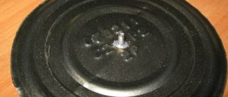
We start by marking the flywheel.
Six holes failed. It turns out not beautiful. The holes are small and the body between them is thin.
In one go we sharpen the counterweights for the crankshaft. The bearings are pressed in. Subsequently, the bearings are pressed out and an M3 thread is cut in their place.
I milled it, but you can also use a file.
This is part of the connecting rod. The rest is soldered with PSR.
Working with a reamer over the sealing washer.
Drilling the Stirling bed. The hole that connects the displacer to the working cylinder. 4.8 drill for M6 thread. Then it needs to be turned off.
Drilling the working cylinder liner for reaming.
Drilling for M4 thread.
How it was done.
Dimensions are given taking into account the conversion. Two pairs of cylinder-piston, 10mm, were made. and by 15mm. Both were tested. If you set the cylinder to 15mm. then the piston stroke will be 11-12mm. and it doesn't work. But 10mm. with a stroke of 24mm. just right.
Dimensions of connecting rods. Brass wire Ф3mm is soldered to them.
Connecting rod mounting assembly. The version with bearings did not work. When the connecting rod is tightened, the bearing is deformed and creates additional friction. Instead of a bearing I made Al. bushing with bolt.
Dimensions of some parts.
Some dimensions for the flywheel.
Some sizes of how to mount on the shaft and joints.
We place a 2-3mm asbestos gasket between the cooler and the combustion chamber. It is also advisable to place paronite gaskets or something that conducts less heat under the bolts that hold both parts together.
The displacer is the heart of Stirling; it must be light and conduct little heat. The stock was taken from the same old hard drive. This is one of the linear motor guides. Very suitable, hardened, chrome plated. In order to cut the thread, I wrapped a soaked rag around the middle and heated the ends until red hot.
Connecting rod with working cylinder. Total length 108mm. Of these, 32mm is a piston with a diameter of 10mm. The piston should move into the cylinder easily, without noticeable scuffing. To check, close it tightly with your finger from below, and insert the piston from above, it should release down very slowly.
I planned to do this but made changes during the process. In order to find out the stroke of the working cylinder, we move the displacer into the refrigerating chamber, and extend the working cylinder by 25 mm. We heat the heat chamber. We carefully place a ruler under the working connecting rod and remember the data. We push the displacer sharply, and how much the working cylinder moves is its stroke. This size plays a very important role.
View of the working cylinder. Connecting rod length 83mm. The stroke is 24mm. The handwheel is attached to the shaft with an M4 screw. His head is visible in the photo. And in this way the counterweight of the displacer connecting rod is attached.
View of the displacer connecting rod. The total length with the displacer is 214 mm. Connecting rod length 75mm. Stroke 24mm. Pay attention to the U-shaped groove on the flywheel. Made for power take-off. The idea was either a generator or through a pin to the cooler fan. The flywheel pylon has dimensions 68x25x15. The top part is milled on one side to a depth of 7mm and a length of 32mm. The center of the bearing from the bottom is at 55mm. Fastened from below with two M4 bolts. The distance between the centers of the pylons is 126mm.
View of the combustion chamber and cooler. The engine housing is pressed into the pylon. The dimensions of the pylon are 47x25x15, the recess for landing is 12 mm. It is attached to the board from below with two M4 bolts.
Lamp 40mm. in diameter height 35mm. Recessed into the shaft by 8mm. At the bottom in the center there is an M4 nut sealed and secured with a bolt from below.
Finished look. Oak base 300x150x15mm.
I've been looking for a working scheme for a long time. I found it, but it was always due to the fact that either there was a problem with the equipment or with the materials. I decided to make it like a crossbow. After looking at many options and figuring out what I had available and what I could do myself with my own equipment. I didn’t like the dimensions that I immediately figured out when the device was assembled. It turned out to be too wide. I had to shorten the cylinder frame. And the flywheel should be placed on one bearing (on one pylon). The materials of the flywheel, connecting rods, counterweight, sealing washer, lamp and working cylinder are bronze. The pylons, working piston, cylinder frame cooler and washer with threads from the heat chamber are aluminum. Flywheel shaft and displacer rod steel. Stainless steel combustion chamber. Graphite displacer. And I’ll put it on display for you to judge.
Source: zaryad.com
https://youtu.be/E0SZuV8MNeE
The simplest engines assembled in 5 minutes
The first single-pole Faraday motor can be assembled in one minute. Very few parts required. All of them, with the exception of the carving, are in the photo.
Neodymium magnet required:
an axially magnetized disk or rod (south pole on one side and north pole on the other). Any of the four in the photo will do.
Screw, nail or self-tapping screw
made of magnetizable material. Length about 45 mm. Shorter or longer ones may reduce the rotation speed. The sharp end makes work easier and faster.
Battery
AA 1.2 V electric cable is of adequate length.
The device is assembled in this way: a magnet is attached to the screw head. The end of the screw is then magnetized towards the battery. Current is supplied to the magnet through the sliding contact. The rotation begins.
By changing the poles of the magnet or the polarity of the battery, the motor moves in the opposite direction.
The second motor is linear. This is not rotation, but linear movement.
it consists of one AAA battery, two 8*8* cubic neodymium magnets
8 mm and twisted copper wire, forming a kind of tunnel with a diameter of 12 mm. But it is better to use round magnets.
The wire must be without insulation! Its diameter is 0.5 mm. The diameter of the marker on which it was screwed is 11 mm. The direction of movement depends on the type of winding (clockwise, counterclockwise) and on the outer poles of the magnets. The magnets to the battery must be supplied with the same poles; accordingly, the outer poles also always have the same name. Another working video.
The following video shows the movement of a battery with neodymium magnets in an elongated spring (approximately 5 mm between turns).
You can create a circular spring so that the “train” moves in a circle without stopping.
Powerful DIY Stirling engine
The Stirling engine, once famous, was forgotten for a long time due to the widespread use of another engine (internal combustion). But today we hear more and more about him. Maybe he has a chance to become more popular and find his place in a new modification in the modern world?
The Stirling engine is a heat engine that was invented in the early nineteenth century. The author, as is clear, was a certain Stirling named Robert, a priest from Scotland. The device is an external combustion engine, where the body moves in a closed container, constantly changing its temperature.
Due to the spread of another type of motor, it was almost forgotten. Nevertheless, thanks to its advantages, today the Stirling engine (many amateurs build it at home with their own hands) is making a comeback again.
The main difference from an internal combustion engine is that the heat energy comes from outside, and is not generated in the engine itself, as in an internal combustion engine.
Engine configuration. Trial and error
After much thought (and years of frustration), I realized there were some bugs in this setup. First of all, in any Stirling engine, the heater, regenerator and refrigerator must be “monoblock”, that is, located in close proximity to each other. This means that all three of these thermodynamic components need to be kept away from the engine's displacer and not "scattered" across the entire throttle path as I did on the MK I. This clever design is very important for good performance and with this design the narrow monoblock layout is clearly visible on all Philips engines. The fact that I placed the regenerator in close contact with the engine block contributed to heat loss along the entire length of the engine, clearly a bad decision in the Stirling design.
Principle of operation
You can imagine a closed air volume enclosed in a housing with a membrane, that is, a piston. When the housing heats up, the air expands and does work, thus bending the piston. Then cooling occurs and it bends again. This is the cycle of operation of the mechanism.
It is no wonder that many people make their own thermoacoustic Stirling engine at home. This requires the bare minimum of tools and materials, which can be found in everyone’s home. Let's look at two different ways to easily create one.
The first type of engine. "Alpha"
The first model to be used was Stirling's Alpha. The peculiarity of its design is that it has two power pistons located in separate cylinders. One of them had a fairly high temperature and was hot, the other, on the contrary, was cold. Inside the high-temperature heat exchanger there was a hot cylinder-piston pair. The cold steam was inside a heat exchanger at a low temperature.
The main advantages of external combustion heat engines were that they had high power and volume. However, the temperature of the hot steam was too high. Because of this, some technical difficulties arose in the process of manufacturing such inventions. The regenerator of this device is located between the hot and cold connecting tubes.
How to do
A firebox and two cylinders for the base are prepared from tin, of which the Stirling engine, made with your own hands, will consist. The dimensions are selected independently, taking into account the purposes for which this device is intended. Let's assume that the motor is being made for demonstration. Then the development of the master cylinder will be from twenty to twenty-five centimeters, no more. The remaining parts must adapt to it.
At the top of the cylinder, two protrusions and holes with a diameter of four to five millimeters are made to move the piston. The elements will act as bearings for the location of the crank device.
Next, they make the working fluid of the motor (it will become ordinary water). Tin circles are soldered to the cylinder, which is rolled into a pipe. Holes are made in them and brass tubes from twenty-five to thirty-five centimeters in length and with a diameter of four to five millimeters are inserted. At the end, they check how sealed the chamber has become by filling it with water.
Next comes the turn of the displacer. For manufacturing, a wooden blank is taken. The machine is used to ensure that it takes the shape of a regular cylinder. The displacer should be slightly smaller than the diameter of the cylinder. The optimal height is selected after the Stirling engine is made with your own hands. Therefore, at this stage, the length should include some margin.
The spoke is turned into a cylinder rod. A hole is made in the center of the wooden container that fits the rod, and it is inserted. In the upper part of the rod it is necessary to provide space for the connecting rod device.
How to do
Foam rubber is very often used to make a simple, low-power Stirling engine at home with your own hands. A displacer for the motor is prepared from it. Cut out a foam circle. The diameter should be slightly smaller than that of a tin can, and the height should be slightly more than half.
A hole is made in the center of the cover for the future connecting rod. To ensure that it runs smoothly, the paper clip is rolled into a spiral and soldered to the lid.
The foam circle is pierced in the middle with a thin wire and a screw and secured on top with a washer. Then the piece of paper clip is connected by soldering.
The displacer is pushed into the hole in the lid and connected to the can by soldering to seal it. A small loop is made on the paperclip, and another, larger hole is made in the lid.
The tin sheet is rolled into a cylinder and soldered, and then attached to the can so that there are no cracks left at all.
The paperclip is turned into a crankshaft. The spacing should be exactly ninety degrees. The knee above the cylinder is made slightly larger than the other.
The remaining paper clips are turned into shaft stands. The membrane is made as follows: the cylinder is wrapped in polyethylene film, pressed and secured with thread.
The connecting rod is made from a paper clip, which is inserted into a piece of rubber, and the finished part is attached to the membrane. The length of the connecting rod is made such that at the lower shaft point the membrane is drawn into the cylinder, and at the highest point it is extended. The second part of the connecting rod is made in the same way.
One is then glued to the membrane and the other to the displacer.
The legs for the jar can also be made from paper clips and soldered. For the crank, a CD is used.
Now the whole mechanism is ready. All that remains is to place and light a candle under it, and then give a push through the flywheel.
Stirling engine power plants - simplicity, efficiency and environmental safety
Ecology of consumption. Science and technology: The Stirling motor is most often used in situations where an apparatus for converting thermal energy is required, characterized by simplicity and efficiency.
Less than a hundred years ago, internal combustion engines tried to gain their rightful place in the competition among other available machines and moving mechanisms. Moreover, in those days the superiority of the gasoline engine was not so obvious. Existing machines powered by steam engines were distinguished by their quietness, excellent power characteristics for that time, ease of maintenance, and the ability to use various types of fuel. In the further struggle for the market, internal combustion engines, due to their efficiency, reliability and simplicity, gained the upper hand.
The further race to improve units and driving mechanisms, which gas turbines and rotary types of engines entered in the mid-20th century, led to the fact that, despite the supremacy of the gasoline engine, attempts were made to introduce a completely new type of engine onto the “playing field” - thermal, for the first time invented back in 1861 by a Scottish priest named Robert Stirling. The engine received the name of its creator.
History of creation
In 1816, Scottish native Robert Stirling patented a heat engine, which today is named after its creator.
However, the very idea of hot air engines was not invented by him. But the first conscious project to create such a unit was implemented by Stirling. He improved the system by adding a purifier, which in the technical literature was called a heat exchanger. Thanks to this, the performance of the motor has greatly increased by keeping it warm. This model was considered the most durable for that time, since it never exploded. Despite such rapid success in promoting the model, at the beginning of the twentieth century, further development of the external combustion engine was abandoned due to its cost in favor of the internal combustion engine.
STIRLING ENGINE: PHYSICAL SIDE OF THE ISSUE
To understand how a tabletop Stirling power plant works, you need to understand a general understanding of the operating principles of heat engines. Physically, the principle of operation is to use mechanical energy, which is obtained when gas expands when heated and its subsequent compression when cooled. To demonstrate the principle of operation, we can give an example based on an ordinary plastic bottle and two pans, one of which contains cold water, the other hot.
When lowering the bottle into cold water, the temperature of which is close to the temperature at which ice forms and the air inside the plastic container is sufficiently cooled, it should be closed with a stopper. Further, when the bottle is placed in boiling water, after some time the cork “shoots” with force, since in this case the work done by the heated air was many times greater than that done during cooling. If the experiment is repeated many times, the result does not change.
The first machines that were built using the Stirling engine accurately reproduced the process demonstrated in experiment. Naturally, the mechanism required improvement, which consisted in using part of the heat that the gas lost during the cooling process for further heating, allowing the heat to be returned to the gas to accelerate heating.
But even the use of this innovation could not save the situation, since the first Stirlings were large in size and had low power output. Subsequently, attempts were made more than once to modernize the design to achieve a power of 250 hp. led to the fact that in the presence of a cylinder with a diameter of 4.2 meters, the actual power output produced by the Stirling power plant of 183 kW was in fact only 73 kW.
All Stirling engines operate on the principle of the Stirling cycle, which includes four main phases and two intermediate ones. The main ones are heating, expansion, cooling and compression. The transition stage is considered to be the transition to the cold generator and the transition to the heating element. The useful work performed by the engine is based solely on the temperature difference between the heating and cooling parts.
Currently there are no plans or drawings for this generator
I have no plans to either produce this engine or sell plans for making its parts. This is a strictly scientific project to demonstrate the viability of this product. Difficulties and costs in the manufacture of some components were offset by the choice of average hobby-quality workmanship. Also, there are compromises in the use of RV-2 compressor elements for this engine, which will not be present in the ideal design. If this is the case, then to improve performance it would require all the thermodynamic components being housed in-house - that is, a redesigned crankcase, pistons, connecting rods, etc. Only then will it be a product that can have a certain market potential.
Please watch my new YouTube videos to see how the development progresses. I sincerely thank you all for your interest!
Dave Kirk
Kirk Engines, Inc.
Below are some data from the video itself.
More recently, a complete overhaul of the heater, regenerator and refrigerator was carried out and new components were manufactured. This variant, the SV-2 MKII, includes all the niceties needed to achieve your goals. The heater head is made from billet 316 steel using an electrical discharge process. The dome and flange are welded in place. Both internal and external fins are used to enhance heat exchange with the working fluid.
External heater fins and welding seam
Internal heater fins and weld seam
The regenerator has a 316 stainless steel body using stainless steel wrap as regenerator material. The thickness is 0.001 inches. This part is made in the form of a cylindrical container. End shields hold the foil in place.
Regenerator housing
The cooler is made from 6061 T-6 aluminum alloy, also using an electrical discharge process. The outer ring forms a bypass channel for coolant. The heater, regenerator and cooler are combined into a “stack” and sealed using O-rings
Note the 1 cubic centimeter located nearby
Stirling engine refrigerator with water jacket
The compression zone cylinder head is made of billet aluminum. The connecting channel is made of thick-walled copper pipe.
Stirling engine compression pump
The “stack” is reinforced with 4 load-bearing bolts with a diameter of 0.313 on ring-shaped clamps. This design minimizes heat leakage deep into the engine structure.
Ring clamps on a stirling engine
Thank you
MODERN STIRLING CONFIGURATIONS
Modern engineering distinguishes three main types of such engines:
- alpha stirling, the difference of which is two active pistons located in independent cylinders. Of all three options, this model has the highest power, having the highest heating piston temperature;
- beta stirling, based on one cylinder, one part of which is hot and the other cold;
- Gamma Stirling, which in addition to the piston also has a displacer.
The production of the Stirling power plant will depend on the choice of engine model, which will take into account all the positive and negative aspects of such a project.
Important points if you are making the engine yourself
When making a Stirling motor, follow the recommendations.
1. The walls of the cylinder where the displacer runs must be made so as not to conduct heat. 2. One edge of the cylinder is cold, the other is hot. The greater the temperature difference, the higher the operating efficiency. 3. There must be a gap between the cylinder walls and the displacer (3 mm is enough) so that there is room for air to leak from the cold chamber into the hot one. 4. There should be no air leaks (keep them to a minimum). This is one of the main reasons that prevent the engine from working. 5. Remove all friction as much as possible. Use silicone grease - it gives very good results. Good luck with your technical creativity!
In another material about how to adapt a current generator for this engine. And here is another model that you can assemble at home.
ADVANTAGES AND DISADVANTAGES
Due to their design features, these engines have a number of advantages, but they are not without disadvantages.
Tabletop Stirling power station, which cannot be purchased in a store, but only from hobbyists who independently assemble such devices, include:
- large sizes, which are caused by the need for constant cooling of the working piston;
- the use of high pressure, which is required to improve engine performance and power;
- heat loss, which occurs due to the fact that the generated heat is transferred not to the working fluid itself, but through a system of heat exchangers, whose heating leads to a loss of efficiency;
- a sharp reduction in power requires the use of special principles that differ from those traditional for gasoline engines.
Second sample. "Beta"
The second sample was Stirling's Beta model. The main design difference was that there was only one cylinder. One of its ends acted as a hot pair, while the other end remained cold. A piston moved inside this cylinder, from which power could be removed. There was also a displacer inside, which was responsible for changing the volume of the hot working area. This equipment used gas that was pumped from a cold zone to a hot zone through a regenerator. This type of external combustion engine had a regenerator in the form of an external heat exchanger or was combined with a displacer piston.
AREAS OF APPLICATION OF STIRLING ENGINES
The Stirling motor is most often used in situations where a device for converting thermal energy is required that is simple, while the efficiency of other types of thermal units is significantly lower under similar conditions. Very often, such units are used to power pumping equipment, refrigerators, submarines, and energy storage batteries.
One of the promising areas for the use of Stirling engines is solar power plants, since this unit can be successfully used to convert the energy of solar rays into electrical energy. To carry out this process, the engine is placed at the focal point of a mirror that accumulates solar rays, which provides permanent illumination of the area requiring heating. This allows solar energy to be focused on a small area. The fuel for the engine in this case is helium or hydrogen. published econet.ru
Did you like the article? Then support us, click
:
Source: econet.ru
DIY high power Stirling engine
In piston Stirling engines, the main friction occurs in the cylinder-piston movable joints. Minimize bearing friction in any way possible. The lower it is, the higher the removed efficiency and, accordingly, the higher the engine speed. Bearing quality is very important for low temperature Gamma Stirlings. In the simplest models, bearings are not used as such. They simply make holes in the tin racks according to the diameter of the crankshaft. Several washers are put on the crankshaft itself to remove lateral friction of the flywheel or side slip clamps. This method is quite effective. But there is a common mistake. Holes are punched with an awl or nail. The edges come out torn and the diameter does not always correspond to the diameter of the shaft. There is a slight backlash. The result is a decrease in engine speed. In the low-temperature but high-revving Gamma-Stirling, backlash reduces engine speed by 20-30%. In addition, play in the bearings has a bad effect on balancing. The aesthetics of the engine also suffers. It operates with a knocking and squeaking sound. In general, it’s not very pleasant. In some cases, if the model is correctly balanced and has low friction in all nodes, a self-starting effect is observed after supplying a heat source. Looks very impressive! Strive for this quality of workmanship. ______________
A regenerator or heat exchanger is a device for saving energy supplied to Stirling. The simplest regenerator is made of steel, less often copper wire or multilayer mesh. The meaning of its work is to select part of the heat from the heated working fluid passing through the regenerator from the hot cavity and then return it to the cooled working fluid moving from the working cylinder. In the future, we will publish simplified methods for calculating the regenerator for Stirling models. In the meantime, let's note that Stirling is economical. comparable and superior to internal combustion engines is mainly achieved through proper regenerator design. Regenerators are not often used in modeling. For engines with small displacements, the dimensions of the regenerator are comparable to the dimensions of the hot and cold cylinder chambers. As a result, the additional dead volume created almost completely “devours” the increase in efficiency. The only exception may be the annular slot regenerator used in the design of the Beale engine. This option can be recommended for use in high-temperature Stirling models. Otherwise, regenerators are “unplowed fields” for the researcher. In any case, there is very little detailed information in open sources today. The regenerator is the “know-how” of any developer of Stirling machines. So - go for it! ______________
System pressure.
The engine power is very significantly influenced by the base pressure of the working fluid in the system. It all depends on the correct calculation and high-quality performance of the engine. In any case, an increase in pressure leads to an increase in power. In some models, doubling the pressure gives the same increase in power. If all of the above forcing methods have been completed, increase the pressure. A car electric pump is suitable as a compressor. On average, it provides pressure from 4 to 7 atmospheres (depending on the manufacturer). To control pressure, all such car pumps are equipped with pressure gauges, which facilitates control and safety. As a last resort, you can use a hand pump, equipping it with a receiver and a pressure gauge. ______________
Source: vk.com
Stirling from GM
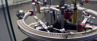
Serious work to improve the external combustion engine, which began 150 years after its invention, has already borne fruit. Various design options for an engine operating on the Stirling cycle have been proposed. There are designs of motors with an inclined washer to regulate the stroke of pistons, a rotary engine has been patented, in one of the rotor sections of which compression occurs, in the other - expansion, and heat is supplied and removed in the channels connecting the cavities. The maximum pressure in the cylinders of individual samples reaches 220 kg/cm2, and the average effective pressure reaches 22 and 27 kg/cm2 and more. Efficiency increased to 150 g/hp/hour. The greatest progress was achieved by General Motors, which in the 1970s built a V-shaped Stirling with a conventional crank mechanism. One cylinder is working, the other is compression. Only the working piston is located in the worker, and the displacer piston is located in the compression cylinder. A heater, regenerator and cooler are located between the cylinders. The phase shift angle, in other words, the angle of lag of one cylinder from the other, in this “Stirling” is 90°. The speed of one piston should be maximum at the moment when the speed of the other is zero (at top and bottom dead centers). The phase shift in the movement of the pistons is achieved by positioning the cylinders at an angle of 90°. Structurally, this is the simplest “stirling”. But it is inferior to the engine with a diamond crank mechanism in balance. To completely balance the inertial forces in a V-shaped engine, the number of its cylinders must be increased from two to eight.
Schematic diagram of a V-shaped Stirling
: 1 - working cylinder; 2 - working piston; 3 - heater; 4 - regenerator; 5 - heat-insulating coupling; 6 — cooler; 7 - compression cylinder.
The operating cycle in such an engine proceeds as follows. In the working cylinder 1 gas (hydrogen or helium) is heated, in the other, compression cylinder 7 it is cooled. When the piston moves upward in cylinder 7, the gas is compressed - the compression stroke. At this time, piston 2 in cylinder 1 begins to move down. Gas from cold cylinder 7 flows into hot cylinder 1, passing sequentially through cooler 6, regenerator 4 and heater 3 - heating stroke. Hot gas expands in cylinder 1, doing work - the expansion stroke. When piston 2 moves upward in cylinder 1, gas is pumped through regenerator 4 and cooler 6 into cylinder 7—the cooling stroke. This “stirling” scheme is most convenient for reversing. In the combined housing of the heater, regenerator and cooler (their structure will be discussed later) dampers are made for this purpose. If you move them from one extreme position to the other, the cold cylinder will become hot, and the hot cylinder will become cold, and the engine will rotate in the opposite direction. The heater is a set of heat-resistant stainless steel tubes through which the working gas passes. The tubes are heated by the flame of a burner adapted for burning various liquid fuels. The heat from the heated gas is stored in the regenerator. This unit is of great importance for obtaining high efficiency. It will serve its purpose if it transfers approximately three times more heat than the preheater, and the process takes less than 0.001 seconds. In a word, this is a fast-acting heat accumulator, and the heat transfer rate between the regenerator and the gas is 30,000 degrees per second. The regenerator, whose efficiency is 0.98 units, consists of a cylindrical body in which several washers made of wire tangle (wire diameter 0.2 mm) are arranged in series. To prevent heat from being transferred to the refrigerator, a heat-insulating coupling is installed between these units. And finally, the cooler. It is made in the form of a water jacket on the pipeline. Stirling power is regulated by changing the working gas pressure. For this purpose, the engine is equipped with a gas cylinder and a special compressor.
How to make a working Stirling engine at home?
Dmitry Petrakov, by popular demand, has filmed step-by-step instructions for assembling a powerful Stirling engine relative to its size and heat consumption. This model uses materials that are accessible to every viewer and widespread; anyone can acquire them. The author selected all the sizes presented in this video based on many years of experience working with Stirlings of this design, and for this particular specimen they are optimal.
This model uses materials that are accessible to every viewer and widespread, thanks to which anyone can acquire them. All the sizes presented in this video were selected based on many years of experience working with Stirlings of this design, and for this particular specimen they are optimal.
With feeling, sense and arrangement. Stirling motor in operation with a load (water pump).
The water pump, assembled as a working prototype, is designed to work in tandem with Stirling engines. The peculiarity of the pump lies in the small amount of energy required to perform its work: this design uses only a small part of the dynamic internal working volume of the engine, and thus has a minimal effect on its performance.
New design and appearance of MK II
At that moment I realized that a major upgrade was needed in order to get a good and efficient engine. Digging through my technical reference books and books, I implemented upgrades to all thermodynamic components in the gas loop. The following were redesigned: a 316 stainless steel heating cylinder head with internal and external fins, a foil for the regenerator, a finned cooler, and a new thin-walled stainless steel displacer.
Ribbed stainless steel Stirling engine heater inside and outside
My friend and Stirling enthusiast John Archibald agreed to prepare drawings from my design sketches and use his skills as a machinist to help create some of the more complex parts. It took a few more years to get all the new components, but at the end of 2012, the MK II version of the engine was ready and assembled.
Cooler with fins for Stirling engine
Stirling motor from a tin can
To make it, you will need available materials: a can of canned food, a small piece of foam rubber, a CD, two bolts and paper clips.
Foam rubber is one of the most common materials used in the manufacture of Stirling motors. The engine displacer is made from it. We cut out a circle from a piece of our foam rubber, make its diameter two millimeters less than the inner diameter of the can, and its height a little more than half of it.
We drill a hole in the center of the cover into which we will then insert the connecting rod. To ensure smooth movement of the connecting rod, we make a spiral from a paper clip and solder it to the cover.
We pierce the foam circle of foam rubber in the middle with a screw and secure it with a washer at the top and at the bottom with a washer and nut. After this, we attach a piece of paper clip by soldering, having first straightened it.
How to Make a Simple Stirling Engine (with Photos and Video)
Let's make a Stirling engine.
A Stirling engine is a heat engine that operates by cyclically compressing and expanding air or other gas (working fluid) at various temperatures so that there is a net conversion of thermal energy into mechanical work. More specifically, the Stirling engine is a closed-cycle regenerative thermal engine with a continuously gaseous working fluid.
Stirling engines have higher efficiency than steam engines and can reach 50% efficiency. They are also capable of operating silently and can use almost any heat source. The thermal energy source is generated externally to the Stirling engine rather than through internal combustion as is the case with Otto cycle or diesel cycle engines.
Stirling engines are compatible with alternative and renewable energy sources as these may become increasingly important as the price of traditional fuels rises and in light of issues such as oil depletion and climate change.
In this project we will give you simple instructions on how to build a very simple motor
DIY
Stirling using a test tube and syringe
.
How to make a simple Stirling engine – Video
Components and Steps to Make a Stirling Motor
1. A piece of hardwood or plywood
This is the basis for your engine. Thus, it must be rigid enough to cope with the movements of the engine. Then make three small holes as shown in the picture. You can also use plywood, wood, etc.
2. Marble or glass balls
In the Stirling engine, these balls perform an important function. In this project, the marble acts as a displacer of hot air from the warm side of the test tube to the cold side. When marble displaces hot air, it cools.
3. Sticks and screws
Pins and screws are used to hold the test tube in a comfortable position for free movement in any direction without any interruption.
4. Rubber pieces
Buy an eraser and cut it into the following shapes. It is used to hold the test tube securely and maintain its seal. There should be no leakage at the mouth of the tube. If this is the case, the project will not be successful.
The syringe is one of the most important and moving parts in a simple Stirling engine. Add some lubricant inside the syringe so that the plunger can move freely inside the barrel. As air expands inside the test tube, it pushes the piston down. As a result, the syringe barrel moves upward. At the same time, the marble rolls towards the hot side of the test tube and displaces the hot air and causes it to cool (reduce volume).
6.
Test Tube The test tube is the most important and working component of a simple Stirling engine. The test tube is made of a certain type of glass (such as borosilicate glass) that is highly heat resistant. So it can be heated to high temperatures.
External combustion engine
The key difference between the Stirling engine is that the fuel burns outside the cylinder rather than inside it. As a result, the interior remains sealed and perfectly clean, without deposits and without the need for maintenance. It operates almost silently, since there is no detonation of the enriched fuel mixture.
The remaining benefits can be summarized as follows:
- Absolute environmental safety.
- A simpler design ensures high reliability.
- Extremely long service life.
- Omnivorous compared to heat source.
- Very high efficiency.
It is much easier to ensure more complete combustion of fuel outside the cylinder than inside. Heating can be carried out not only from hydrocarbon energy sources, but also from solar energy using high-temperature solar concentrators. In this combination, the efficiency of the alternator exceeds 30%!
For comparison: the best commercial photocells demonstrate an efficiency of only 24%. Quietness was a decisive factor when installing the Stirling engine on the latest series of submarines in Japan and Sweden.
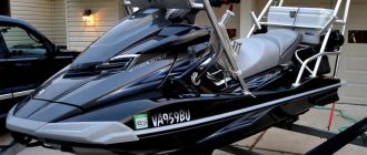
In the mid-80s of the 20th century in the USA, the Stirling engine was assembled and installed on the Chevrolet Celebrity car (Chevrolet Celebrity MOD 2 Stirling)
Pictured is an AMC Spirit Stirling Experimental Engines
The results were unexpected: a muffler, lubrication and catalysts were no longer required, fuel savings were up to 45%, and acceleration remained virtually unchanged.
Pictured is a NASA Dodge D-150 with a Stirling engine.
Stirling engines are also used by NASA in spacecraft.
But they also have disadvantages.
To achieve the maximum efficiency achievable in practice, it is necessary to ensure a very large temperature difference between the cold and hot parts of the cylinder. Otherwise, the “power density” decreases.”
In the photo there is a P-40 OPEL STIRLING ENGINE
The ideal working fluid (gas) is hydrogen, but its molecules are so small that they can “saturate” the material of the cylinder. The second most efficient gas is helium, but it is expensive. And efficiency decreases by 5%. But you can use nitrogen, ammonia and even dry air. But the power will be less than ideal.