Principle of operation
All level indicators are based on multi-stage comparators.
Comparator – a logical element that compares the parameters of two incoming signals.
The signal being analyzed is supplied to one channel of the comparator, and the reference comparison voltage is supplied to the second. If the amplitude of the first is higher than the reference voltage, a logical one appears at the output, if lower, a logical zero appears.
The operation of the simplest comparator can be demonstrated on the K155LN1 microcircuit, the unit cluster of which is the “NOT” element.
Such a microcircuit is the simplest logical comparator. When the input voltage is from 0V to 2.4V (which corresponds to logic zero) the output is 2.7V, as soon as the input voltage exceeds 2.4V, the output signal will drop to zero volts.
There are several chips for level visualization. The most multifunctional circuits, in my opinion, allow you to create microcircuits based on the lm39xx architecture. This line includes three microcircuits: lm3914, lm3915 and lm3916. Minimal decoupling easily allows you to create an LED sound level indicator with your own hands, even without deep knowledge of radio electronics.
All of them represent a ten-band analyzer. They differ in the way they differentiate the input signal. For lm3914 it is 1V, for lm3915 it is 3dB, for lm3916 it is 1db.
Add a link to a discussion of the article on the forum
RadioKot >Articles >
| Article tags: | Add a tag |
Sound indicators.
Author: Yuri Zotov Published 04/08/2008
Part I. Dial indicators.
Dial indicators, with an arrow oscillating to the beat of the music, still look quite modern on the front panels of amplifiers. And if the presence of such indicators was really necessary before, now there is no urgent need for them. However, judging by similar questions on the Internet, there are still fans of such things. This article was written just for them.
1. Pointer device.
Design.
The design of such devices is varied, but their operating principles are the same. A cylindrical magnet is housed in a plastic case. A magnetic frame with a spring-loaded suspension and a fixed arrow is installed along the generatrix of the cylinder. A balancer is installed on the side opposite to the arrow. In most cases, such a balancer is a drop of solder and serves to compensate for the centrifugal forces of the pointer. Since the device is, at its core, a mechanical system, the main characteristics are determined by the “mechanics” of the measuring head. I would like to note one more feature of the design of dial indicators: a spring is used to return the needle to its original position (and this is not a linear element, depending on its rigidity), as a result, the measurement scale of the device will also not be linear. Modern measuring heads use multi-turn springs with fairly good flexibility and the nonlinearity of the measurement is very small, but still, it seems to me, it’s worth remembering.
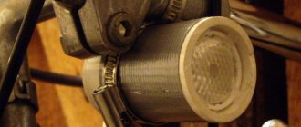
The figure above shows the measuring head model M6850 as the most common and accessible, at the moment, to many beginning radio amateurs. Personally, I worked out all my schemes on it.
Operating principle.
It’s simple: a current is applied to the coil, a magnetic field is created.
The interaction of the magnetic field of the coil with the magnetic field of the permanent magnet leads to deflection of the coil (and the needle) in proportion to the current flowing in it. The direction of the current flowing in the coil determines the direction of deflection of the arrow. Hence the conclusion: the dial indicator only works with direct (pulsating) current.
Applying alternating current to the indicator will cause the needle to “tremble” and nothing more.
2. What to measure.
Well, everything seems to be clear: we measure the amount of alternating voltage in the sound path. In measurement practice, the following are known: the maximum value (amplitude value) of the signal, the average rectified value, the root mean square value of the signals. We will not delve into the depths of theories; we will only determine that in our case, we measure the rectified average value. And the scales of our devices are calibrated in decibels (less often as a percentage) of the established “reference” signal level (“0” dB). That is, we will measure not the signal magnitude itself, but its ratio to some reference value K = Ureference/Umeasured. , expressed in decibels. To convert measured values into decibels, use the following formula: A = 20 Lg Ustandard/Umeasured. All sorts of things. In portable tape recorders, the dial indicator was also used to measure the voltage of the supply elements, that is, it was, in essence, a primitive voltmeter.
3. How to measure.
From what I wrote above, a logical conclusion follows: in order for the indicator to work as we expect, it is necessary to convert the alternating current into a direct current proportional to it and apply it to the measuring head. The first thing that comes to mind is shown in the figure:
Oddly enough, but such an indicator will work. After a little “retouching”, it takes on the following appearance:
And it may well work, say, when measuring the output power of some power amplifier. Well, what can be said about such a scheme in general? It works in the following way: the excess signal to the required value is extinguished by a resistive divider R1, R2. The diode converts the alternating signal into a constant (pulsating) signal by cutting off the “negative” half-wave of the audio signal. The signal obtained in this way is “smoothed” on capacitor C1 and then goes to the measuring head. The response and recovery time of the meter depends on this capacitor. Up to certain values, of course... Is the scheme good or bad? Here are its pros and cons. Pros: 1 - simplicity of the scheme. 2 - minimum details. 3 - does not require a power source. Well, that seems to be all... Cons: 1 - Low measurement accuracy due to the installed half-wave rectifier (VD1). 2 - Low input resistance, determined mainly by resistor R1. This is precisely what allows it to be used only with signal sources with low output impedance (as mentioned above, with power amplifiers). 3 - Small measuring range. At low power values, the oscillations of the needle will be practically unnoticeable. Obviously, for greater versatility of the meter, improved circuitry is required. Again, the first thing that suggests itself is the use of a “buffer” with a large input and low output resistance. The simplest way seems to be to use a transistor as a DC amplifier. Here is one possible scheme:
As you can see, compared to the previous circuit, a transistor VT1 was added, which slightly increased the sensitivity of the circuit. However, other shortcomings remain. Another option for using the transistor is possible - as an emitter follower:
In this case, we get a buffer with high input and low output impedance. However, since the Ktransmission of the emitter follower cannot be greater than one, we will not be able to get any increase in sensitivity from this circuit. Other shortcomings of the meter also remain. Here we come to a circuit that combines amplification properties and low output impedance.
This circuit (in various interpretations) is often used in equipment with single-supply power. I also repeated it more than once and proved high repeatability and stability of work. It eliminates most of the shortcomings of the above schemes. The transistor amplifier on VT1, VT2 has a high input and low output impedance. The circuit can be powered from a source with a voltage of 3 to 25 volts (depending on the transistors used). Not critical to the ratings of passive elements. Of course, there are also disadvantages - a half-wave rectifier VD1, VD2 (note that here it is implemented using a voltage multiplier circuit). As a consequence, there is some measurement inaccuracy. However, the simplicity and versatility of the device more than compensate for this drawback. Due to the availability of integrated operational amplifiers, the above circuit can also be implemented using an op-amp.
As you can see in this circuit, the active element is the operational amplifier. Apart from reducing the number of passive parts, this scheme is almost identical to the previous scheme and contains the same advantages and disadvantages. Since we are talking about the use of operational amplifiers in signal meters, I would like to consider a few more schemes for their implementation.
These options retain the advantages of the circuits described above, but also measure two half-waves of the audio signal through the use of a diode bridge. The circuit shown in the figure on the right, moreover, ensures LINEAR movement of the arrow of the measuring head, since the latter is included in the feedback circuit of the operational amplifier. The sensitivity of the indicators can be adjusted by selecting resistance R3. The input impedance of the indicators is about 47 kOhm. The supply voltage depends on the types of op-amps used, and almost any op-amp with output currents of more than 5mA can be used as an amplifier. But I would recommend using an op-amp with field-effect transistors at the input (K140UD8, KR 544UD2, etc.). In this case, it will be possible to increase the input resistance of the node by simply increasing the values of the resistive dividers at the input (R1, R2).
And one more small nuance. In the above op-amp indicator circuits, other options are possible for supplying half of the supply voltage to the inputs of the amplifiers. However, their characteristics will remain virtually unchanged. But this question is already from the field of op-amp circuit design. In addition, these circuits can be powered with bipolar supply voltage with minimal modifications. Lastly, I would like to consider a signal level meter based on a high-quality specialized K157DA1 microcircuit. Despite its “long life”, in my opinion, it still deserves close attention. This microcircuit contains a full-wave rectifier of the average signal value, a buffer stage and a bipolar to unipolar signal converter. Main electrical parameters:
| Supply voltage | +/-15V |
| Voltage Gain | 7-10 |
| Output voltage | 9V |
| Output quiescent voltage, no more | 50mV |
| Output current of each channel, not less | 2.5mA |
| Current consumption in silent mode | 1.5mA |
| Upper limit operating frequency | 100kHz |
| Input impedance (obtained empirically) | 33-68kOhm |
Typical microcircuit connection circuit:
As you can see, the microcircuit has a small number of attachments, which makes it easier to use not only in dial indicators, but also in other devices, which will be discussed in the second part of the article. What is marked with a dotted line in the diagram may not be installed, but it is worth noting that R3 and R4, when installed, increase the sensitivity of the meter. Since the microcircuit has a wide range of supply voltages, it can also be used in portable (low-voltage) equipment. I even encountered it in the portable tape recorder “Spring-207” (in my opinion, in “Spring -212”), “Rus - 207”.
4. What can be improved?
The indicator head is a mechanical system, which means it has a certain (fixed) response time to a pulse signal. When a signal is given for a sufficiently long duration, the shooter will respond accordingly. When a pulse signal of shorter duration arrives at the head, the meter simply will not be able to adequately respond to it. In such cases, peak signal indicators, usually collected on LEDs, are added to the usual dial indicators. The peak indicator allows you to detect the arrival of a short-duration pulse with a level exceeding a certain threshold. What does the flashing LED indicate? To work in “pair” with the above microcircuit, our industry produced the K157ХП1 microcircuit, which consists of two integrated peak detectors combined with the ARUZ detector. But more on this in the second part of the article.
And finally, I will present an accelerating RC chain designed to partially reduce (compensate) the response time of the pointer device. I used this chain with all the dial indicators I collected. And I recommend it to you.
A small explanation to the diagram: with pulses of sufficient duration, current flows to the dial indicator along the circuit R1, R2, C2. The elements R2 C2 determine the reverse motion of the arrow. When a short pulse appears, the resistance of the circuit R1, R2 C2 is large enough for it, and it passes to the indicator through the accelerating capacitor C1. In practice, this does not look like a “beating” of the needle, but like a quick approach to the left side of the scale, and a slow move to the right. I did not indicate the circuit ratings intentionally, since it is advisable to select them strictly individually. However, when using the M dial indicator, their values were as follows: R1-3.3 kOhm, R2 - 1.2 kOhm, C1-0.22 - 4.7 mF, C2-10 - 47mF.
5. For completeness.
Pointer instruments can be used as indicators of interchannel balance:
As you can see from the diagram, there is nothing complicated here. The rectified currents of the left and right channels are summed up on the measuring head. If the value is equal (modulo), the currents are mutually compensated, and the indicator arrow is at “0”. When the signal level is slightly exceeded, the currents are not fully compensated, and the arrow begins to deviate in the corresponding direction. It is worth noting that such a scheme will work normally with an indicator in which the manufacturer provides for the initial placement of the arrow in the middle of the scale. True, you can also use ordinary indicators, after first applying a DC bias voltage to it. However, I would prefer to simply disassemble the indicator and move the spring suspension holder a little in the desired direction.
6. Conclusion.
Of course, I realize that within the framework of one article it is impossible to consider all the ways of constructing circuits of dial indicators. However, I tried in an accessible form, without citing all kinds of formulas, to present only the basic, PRACTICALLY TESTED methods and schemes for their implementation. Those who are interested and intend to learn more about all this, read literature and visit forums.
As usual, we put the questions here.
| What do you think of this article? | Did this device work for you? | |
| 38 | 3 | 1 |
| 1 | 0 |
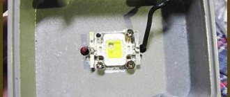
LED audio level indicator on lm3915
Let's assemble a volume indicator on LEDs using comparators on lm3915.
Let's figure out how the scheme works.
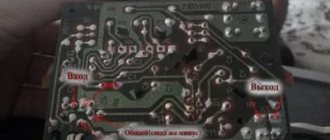
The signal being analyzed is received at input 5; its amplitude should be 10V. To match the amplitude of the incoming signal, we need a transistor switch. The analyzed signal is supplied to its base through a resistor voltage divider at R5.
Logical structure of lm3915
The sound indicator on lm3915 can operate in two indication modes - “dot” and “column”. In the first case, the LED corresponding to the current signal level lights up, in the second – all LEDs from zero to the current level. Switching of indication modes is carried out through a switch between the common wire and input “9”.
Brief description of LM3915
The LM3915 block diagram consists of ten identical operational amplifiers operating on the comparator principle.
The direct inputs of the op-amp are connected through a chain of resistive dividers with different resistance values. Thanks to this, the LEDs in the load light up according to a logarithmic dependence. The inverse inputs receive an input signal, which is processed by a buffer op-amp (pin 5). The internal structure of the IC includes a low-power integrated stabilizer connected to pins 3, 7, 8 and a device for setting the glow mode (pin 9). The supply voltage range is 3–25V. The reference voltage can be set in the range from 1.2 to 12V using external resistors. The entire scale corresponds to a signal level of 30 dB in 3 dB steps. The output current can be set from 1 to 30 mA.
Non-standard application
An indicator using lm3914 can be used as a compact tester for small batteries and accumulators.
The supply voltage of such a circuit is from 5V to 12V. Conveniently powered by Krona or four AAA batteries.
Capacitor C1 - 50 µF 25V, pull-up resistor R1 - 1Mohm. R2, R3 – 4.7-5 kOhm each. The measurement range of the circuit is 1V with a gradation of 0.1V. R2 regulates the measurement range, R3 – LED current. If you turn off output 9, the indication will be a “column”, but the power supply elements are quickly discharged.
Please rate the article. We tried our best:)
Did you like the article? Tell us about her! You will help us a lot :)
On-screen volume indicator for windows 7
Monitoring gadget for...
A unique monitoring gadget for your system. At first glance, an ordinary set of elements for...
Multi gadget for the worker...
An interesting multi-gadget that combines 6 functions. The gadget can do the following: show the load on the processor,...
Gadget for monitoring...
A gadget that allows you to monitor network traffic, both incoming and outgoing. Also monitor your connection speed...
Site navigation
Parts and installation
Now about the radio components: select capacitors C1 and C2 to your liking, I took each 22 μF at 63 V (I don’t recommend taking it for a lower voltage for ULF with an output of 100 Watt), the resistors are all MLT-0.25 or 0.125. All transistors are KT315, preferably with the letter B. LEDs are any that you can get.
Rice. 4. Printed circuit board for ULF output power indicator for 10 cells (click to enlarge)
Rice. 5. Location of components on the printed circuit board of the ULF output power indicator
I didn’t mark all the components on the printed circuit board because the cells are identical and you can figure out what to solder and where without much effort.
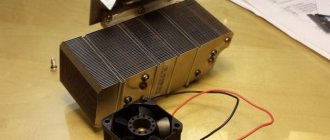
As a result of my labors, four miniature scarves were obtained:
Rice. 6. Ready-made 4 indication channels for ULF with a power of 100 Watts per channel.
Preface
To make output power indicators for my ULF, I chose a transistor circuit. You may ask: why not on microcircuits? — I’ll try to explain the pros and cons.
One of the advantages is that by assembling on transistors, you can debug the indicator circuit with maximum flexibility to the parameters you need, set the desired display range and smoothness of response as you like, the number of indication cells - at least a hundred, as long as you have enough patience to adjust them.
You can also use any supply voltage (within reason), it is very difficult to burn such a circuit, and if one cell malfunctions, you can quickly fix everything. Of the minuses, I would like to note that you will have to spend a lot of time adjusting this circuit to your tastes. Whether to do it on a microcircuit or transistors is up to you, based on your capabilities and needs. We assemble output power indicators using the most common and cheap KT315 transistors. I think every radio amateur has come across these miniature colored radio components at least once in his life; many have them lying around in packs of several hundred and idle.
Rice. 1. Transistors KT315, KT361
The scale of my ULF will be logarithmic, based on the fact that the maximum output power will be about 100 Watts. If you make a linear one, then at 5 Watts nothing will even glow, or you will have to make a scale of 100 cells. For powerful ULFs, it is necessary that there be a logarithmic relationship between the output power of the amplifier and the number of luminous cells.
Pinout of gas-discharge indicators of the IN series
A – anode, E – screen, K – cathode, Kv – auxiliary cathode, A0 – zero anode, A1-A4 – group of anodes, Ap – last anode.