Led cube - what you need for self-assembly
If you are into DIY projects or like to tinker with electronic circuits, try assembling an LED cube with your own hands. First you need to decide on the sizes. Once you understand how the device works, you can upgrade the circuit with either more LEDs or fewer LEDs.
Let's look at how this works using the example of a cube with a side of 8 LEDs. This cube can be intimidating for beginners, but if you are careful when studying the materials, you will easily master it.
To assemble the led cube 8x8x8 you will need:
Connecting the power supply for Arduino
To power the board, you can use a separate 9 volt, 1 ampere adapter. You can use an adapter for a Krona battery and power it from it. Either way, you will need to make another hole for the power wire. When you make the hole, make sure its size is slightly larger than the connector itself.
In general, all that remains for you after this is to upload the sketch to the Arduino and enjoy the result:
Program for LED cube for Arduino
Your cube is ready!
Operating principle of the circuit
Small 5mm type LEDs draw a negligible current of 20mA, but you are going to be lighting quite a lot of them. A 12V and 2A power supply is perfect for this.
You will not be able to connect all 512 LEDs individually because you are unlikely to find a microcontroller (MK) with so many pins. Most often, there are models in cases with a number of legs from 8 to 64. Naturally, you can find options with a large number of legs.
How to connect so many LEDs? Elementary! A shift register is a chip that can convert information from parallel to serial and vice versa - from serial to parallel. By converting serial to parallel, you will get 8 or more signal pins from one signal pin, depending on the register capacity.
Below is a diagram illustrating the working principle of a shift register.
When you supply a bit value, namely zero or one, to the serial Data input, it is transmitted along the edge of the Clock clock signal to parallel output number 0 (do not forget that in digital electronics the numbering starts from zero).
If at the first moment of time there was one, and then within three clock pulses you set the input to zero potential, as a result of this you will get the input state “0001”. You can see this in the diagram on lines Q0-Q3 - these are four bits of parallel output.
How to apply this knowledge in building an LED cube? The fact is that you can use a not quite ordinary shift register, but a specialized driver for LED screens - STP16CPS05MTR. It works on the same principle.
The most interesting part: demo videos + my work
Standard animations (+video)
Analysis of the musical spectrum (+ video)
The implementation of this feature was somehow not particularly impressive, I expected more.
Key “0”
— switches the cube to this mode.
Key “1”
- returns the cube to standard animation playback
Animated display of readings from the DHT22 temperature and humidity sensor (+ video)
I am not so much attracted by the possibility of creating some new abstract animations as by displaying some really useful information on a cube.
For example, from the DHT22 temperature and humidity sensor. But at the same time, I agree that a static display is not very interesting, so I still implemented a simple animation - this is the flight of letters and numbers from the back wall of the cube to the front. The code declares three arrays of unsigned char
:
massBukov[56]
, containing the letters M, Y, S, K, U, B, T
massNumber[40]
, containing the numbers from 0 to 9
massBUF[64]
, a buffer array sent to cube
Since the resolution of one side of the cube is 8x8, we can display on it a maximum of a two-digit number, which will be formed depending on the sensor readings. A letter corresponding to the type of reading will appear before the numeric readings, for example "B"
is for humidity and
"T"
is for temperature. When starting the program, I implemented the display of the name of a familiar resource on which this review was posted. After this, the temperature and humidity per cubic meter are displayed cyclically. To successfully compile this sketch, the DHT library is required.
Sketch for displaying temperature and humidity on a cube
// Output temperature and humidity from the DHT22 sensor // 5V power supply, the signal pin of the sensor is connected to pin 2 of the Arduino and is pulled through a 10K resistor to 5V #include “DHT.h” #define DELAYS 150 #define LAYER 8 #define COLUMN_COUNT 64 DHT dht (2, DHT22); // Output #2 for the sensor void printMass(unsigned char *massP); void printNum(unsigned char number); void printMain(void); unsigned char des, ed, h, t; unsigned char massBUF[64]; unsigned char massBukov[56] = { 0xFF, 0xFF, 0x30, 0x1C, 0x1C, 0x30, 0xFF, 0xFF, // M 0xF0, 0xF8, 0x1C, 0x0F, 0x0F, 0x1C, 0xF8, 0xF0, // Y 0x4C, 0xDE, 0x9B, 0x99, 0x99, 0xD9, 0x7B, 0x32, // S 0x00, 0x81, 0xC3, 0x66, 0x3C, 0x18, 0xFF, 0xFF, // K 0xFC, 0xFE, 0x07, 0x03, 0x03, 0x07, 0xFE ,0xFC, // U 0x00, 0x00, 0x2C, 0x7E, 0x52, 0x7E, 0x7E, 0x00, // B 0x00, 0x60, 0x60, 0x7E, 0x7E, 0x60, 0x60, 0x00 // T }; unsigned char massNumber[40] = { 0x00, 0x7C, 0x44, 0x7C, // 0 // 0 0x00, 0x00, 0x7C, 0x00, // 1 // 4 0x00, 0x74, 0x54, 0x5C, // 2 // 8 0x00, 0x7C, 0x54, 0x54, // 3 // 12 0x00, 0x7C, 0x10, 0x70, // 4 // 16 0x00, 0x5C, 0x54, 0x74, // 5 // 20 0x00, 0x5C, 0x54, 0x7C, // 6 // 24 0x00, 0x7C, 0x40, 0x40, // 7 // 28 0x00, 0x7C, 0x54, 0x7C, // 8 // 32 0x00, 0x7C, 0x54, 0x74 // 9 // 36 }; void setup(void) { dht.begin(); _delay_ms(DELAYS); Serial.begin(38400); Serial.write(0xAD); //command for cube to work from Arduino printMass(massBukov,COLUMN_COUNT,LAYER); printMass(massBukov+8,COLUMN_COUNT,LAYER); printMass(massBukov+16,COLUMN_COUNT,LAYER); printMass(massBukov+24,COLUMN_COUNT,LAYER); printMass(massBukov+32,COLUMN_COUNT,LAYER); } void loop(void) { h = dht.readHumidity(); t = dht.readTemperature(); printNum(h); _delay_ms(500); printMass(massBukov+48,COLUMN_COUNT,LAYER); _delay_ms(600); printNum(t); _delay_ms(600); printMass(massBukov+40,COLUMN_COUNT,LAYER); _delay_ms(600); } void printMass(unsigned char *massP, int razmer, int sdv){ for(int z=0 ; z<8 ; z++) massBUF[z] = massP[z]; for(int y=0; y<8; y++){ printMain(); for (int i=razmer-1 ; i>=0 ; i—){ massBUF = i<4; i++){ massBUF[4+i] = massNumber[des*4+i];//tens massBUF = massNumber[ed*4+i]; //units } printMass(massBUF,COLUMN_COUNT,LAYER); _delay_ms(DELAYS); }
[MENU]
How to connect LEDs?
Of course, using a driver will not completely solve the problems associated with connecting a large number of LEDs. To connect 512 LEDs, you will need 32 such drivers, and even more control legs from the microcontroller.
So we'll go the other way and combine the LEDs into rows and columns, so we get a two-dimensional matrix. The ice cube occupies all three axes. Having finalized the idea of combining an 8x8x8 LED cube in which the LEDs are combined into groups, we can come to the following conclusion:
Combine layers of LEDs (floors) into circuits with a common anode (cathode), and columns into circuits with a common cathode (or anode, if cathodes were combined on floors).
To control such a design you need 8 x 8 = 16 control pins per columns, and one for each floor, there are also 8 floors in total. In total, you need 24 control channels.
The input block receives a signal from three pins of the microcontroller.
To light the required LED, for example, located on the first floor, the third in the first row, you need to apply a minus to column number 3, and a plus to floor number 1. This is true if you have assembled floors with a common anode, and the columns - a cathode. If it is the other way around, the control voltages must be inverted accordingly.
Practical recommendations for successful assembly
In order to make it convenient for you to solder a cube of LEDs, you need:
For the cube of LEDs to work correctly, you need to assemble it in layers with a common cathode, and the columns with an anode. Connect to the Arduino pins what is indicated in the diagram as input in the following sequence:
| Arduino pin no. | Chain name |
| 2 | L.E. |
| 3 | SDI |
| 5 | CLK |
What if I don’t have such skills?
If you are not confident in your abilities and knowledge of electronics, but want such a decoration for your desktop, you can buy a ready-made cube. For those who like to make simple electronic crafts, there are excellent simpler options with 4x4x4 edges.
Cube with face size 4 diodes
Ready-made kits for assembly can be purchased in stores with radio components, as well as a huge selection on Aliexpress.
Assembling such a cube will develop the novice radio amateur's soldering skills, accuracy, correctness and quality of connections. Skills in working with microcontrollers will be useful for further projects, and with the help of Arduino you can learn to program simple toys, as well as automation tools for everyday life and production.
Unfortunately, due to the peculiarities of the Arduino programming language - sketch, there are some limitations in terms of performance, but believe me, when you hit the ceiling of the capabilities of this platform, most likely mastering the work with “pure” MKs will not cause you any significant difficulties.
Source
Wire and decorations
Wire is the most important material that you can find in craft stores. It comes in different colors and textures, but as a rule, the base copper color is the most affordable.
This is what we recommend using for your first works, and only then moving on to more expensive color ones. Also, keep in mind that you can complement your crafts with any decorations, for example, beads, beads and any other material.
In addition to regular wire, you can find flat wire of various widths, twisted and even plastic threads. Usually preference is given to copper, since it is an extremely malleable, soft metal. Children and toddlers will enjoy fiddling with chenille wire because of its slight frills.
Creating a large LED cube
LED cubes will never lose their popularity and attractiveness. There are a huge number of projects for 5x5 and smaller cubes on the Internet. Today we will build a cube of 8x8x8 diodes.
Building a cube is quite challenging for beginners and enthusiasts. Therefore, we tried to simplify this process as much as possible and create instructions that will be extremely detailed and complete, since any minor error can be critical, and it will be quite difficult to eliminate it.
To work on the project, it is enough to have basic soldering skills, have basic knowledge of electronics and be familiar with the operation of Arduino boards.
LED Location
I would like to immediately note that you should not choose large LEDs, as they will block each other and the distant rows will be difficult to see. Also, do not use very bright diodes. So that the light of each diode is point-like.
For the project we will use not very bright 3mm diffuse LEDs with long legs.
For a better view of each LED, we will use very thin connecting wires.
The LEDs will be connected to each other using their legs. Cathodes with cathodes, anodes with anodes. For our cube we will need 8 such matrices.
MATERIALS AND COMPONENTS
Links to stores from which I have been purchasing for more than one year
You will most likely find it useful:
- Arduino NANO 328p – search
- https://ali.ski/tI7blh
- https://ali.ski/O4yTxb
- https://ali.ski/6_rFIS
- https://ali.ski/gb92E-
- Giant4 (Russia)
- LEDs with long legs 100 pieces
- Blue https://ali.ski/EwPQQK
- Pink https://ali.ski/UKge78
- Red https://ali.ski/rseXA
- Green https://ali.ski/suEgC
- Yellow https://ali.ski/1UQZP
- LEDs 10 pieces
- Blue https://ali.ski/4J3IEE
- Pink https://ali.ski/WHmG7
- Red https://ali.ski/bWAD1r
- Yellow https://ali.ski/NfCbf
- Green https://ali.ski/ZmnvJ
- Shift registers 74hc595n https://ali.ski/DnwaZ
- Transistors bd241c https://ali.ski/H9eCm
- Resistors https://ali.ski/cgfwE
- Transistors TIP41C (just in case) https://ali.ski/I9hH_
- Layout 8 by 12 cm https://ali.ski/e8SNm
- Comb https://ali.ski/4ujVt
- Look for buttons and stands in any stores for radio amateurs, since you can only buy a bag of 100 pieces from the Chinese!
Electronic circuit
Creating eight layers of 64 diodes each takes a lot of time, but it is quite simple to do.
The most difficult moment is building a circuit to control the LED cube and finding faults in the circuit, if of course there are any.
The MAX7219 chip will be used to control our cube. It was originally designed to control 7-segment LED displays. Using this chip, we will reduce the number of controls on each layer to a minimum.
To control each layer of 64 diodes you will need:
To create a cube we will need 8 sets of the above components. It's also worth noting that you may need a different resistor for the specific LEDs you'll be using. Its role in this circuit is to limit the maximum voltage that the MAX7219 chip will produce.
To make assembly easier, the cube was divided into two parts. 4 layers on each of them.
The cube can be controlled externally by any microcontroller via the SPI interface. For this project we will be using the popular Arduino (Nano) board. To control our cube using only 3 signal wires (SPI) and 2 power wires (5V DC). You can use the more common Arduino Uno board instead of the Nano. They are very similar (except for size), so there shouldn't be any connection problems.
It is also worth paying attention to the fact that all components should be soldered to the bottom of the printed circuit board.
Jumpers are used to connect the boards together. To connect two boards you need 5 jumpers. To create one block of 4 layers of LEDs you will need 15 jumpers.
Most cubes are solid, unlike ours. And if any LED in the middle of the cube fails, it is quite difficult to get to it. In our case this will not be difficult.
Assembly
Part 1
Basic steps to create one layer:
- Prepare 8 LEDs with cut cathode legs to 10 mm;
- Fill all the holes in the base with LEDs;
- Bend and solder the cathode legs;
- Bend and solder the anode legs;
- Solder the wires to the cathode legs and secure them.
This procedure must be repeated 8 times.
The assembly of one layer of the cube can be seen in the video:
Part 2
- Prepare 15 jumpers;
- Solder jumpers onto the printed circuit board;
- Solder the electronic components to the board;
- Solder a 5-pin right-angle connector for the first layer;
- Cut off the fifth anode contact;
- Insert and solder all anode legs to holes G, F, E, D, C, B, A and DP;
- Insert and solder cathode wires into holes D0, D1, D2, D3, D4, D5, D6 and D7;
- Cut the wires and legs from the back of the board.
The second part of the assembly in the video:
Checking the cube
It is better to check the cube before complete assembly, each layer separately. This will make it easier to fix problems if there are any, of course.
To test, we connect each layer in turn to the Arduino Nano board (you should install the test program in advance). The lines should light up alternately from top to bottom.
You need to download the code to your board and then connect it to the finished cube.
That's all. All that remains is to enjoy the resulting device.
Source
LED cube 3x3x3 on Arduino Uno
You can find quite a few videos on youtube.com that show various colorful LED cubes blinking beautifully and controlled using Arduino. But access to the manufacturing technology and software code of these devices is offered for money. In our article, we will look at creating the simplest similar flashing LED cube 3x3x3 with the simplest blinking algorithm (easier for beginners), on the basis of which you can then program your own samples (patterns) of blinking (switching) of the LEDs of this cube. Moreover, all this will be absolutely free for you - our site does not require any money for reading the information posted on it (unless you intend to distribute it later somewhere - in this case it will be a violation of copyright. Active links on the Internet to articles on allowed on our website).
As shown in the above figure, the 3*3*3 LED cube consists of 27 LEDs arranged in rows and columns to form a cube shape.
Many similar cubes can be designed. The simplest of them will be a 3x3x3 cube. To design a 4*4*4 cube you will already need 64 LEDs. That is, with an increase in the linear dimension of the cube, the complexity of its manufacture increases many times over.
The 3x3x3 LED cube is the easiest to manufacture, not only because it contains quite a few LEDs, but also due to the following conditions:
In most cases, regular LEDs consume 2 to 5 mA of current. Therefore, if we use LEDs that consume 2 mA, then we can control 9 such LEDs without problems from one Arduino Uno pin, since the Arduino Uno pins are capable of providing a current of 20-30 mA.
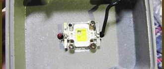
White LEDs were used in this project, but you can use LEDs of any color - with colored LEDs the cube will look even more impressive.
To control this cube, we need 12 pins of the Arduino Uno board.
Programming
I couldn't find programs or libraries that were directly compatible with the panel components, so I had to write my own solution.
It won’t be possible to use a controller and circuit design/firmware like Greg’s now, since the ongoing shortage of microcircuits does not allow us to get all the necessary components. I only had a few microcontrollers at hand, and the choice fell on Arduino Uno. I programmed most of the multiplexing code using low-level instructions, which significantly speeded up the program compared to a version that relied on functions like digitalWrite.
Fundamentally, my program is simple: set up a timer to call interrupts every 1/2400 of a second. In this case, each time you need to read and shift a volume of data, “latch” registers and wait for an interrupt to repeat it all over again.
Debugging such code is a pain, but in the end it works great and pleases with its speed. The Uno doesn't have the ability to generate many sophisticated animation patterns, but I was able to get a nice random flickering effect using very basic 3-bit color. To be honest, this result even surprised me a little.
Required Components
Arduino Uno board, 220 Ohm resistor (3 pcs.), 5 V power supply.
Breadboard, connecting wires, 27 LEDs.
Soldering iron, solder and flux (rosin).
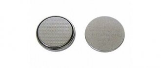
SR2032 battery, some tools.
An empty cardboard box, a pencil, a ruler and several jumpers (connectors).
Construction of a 3x3x3 LED cube
Step 1.
First, you need to use an SR2032 battery or a multimeter to check the LEDs for serviceability, because if it later turns out that some LED is faulty, then replacing it in an already assembled cube will not be very easy.
Step 2.
Then it is necessary to remove the insulation from the connecting wires as shown in the figure. You can use any jumper wires to create the cube, but it's worth noting that breadboard wires will work just fine for this purpose. Then the resulting bare wires must be cut into pieces 7 cm long - a total of 6 such pieces are needed. These pieces of wire will be used to bond the layers of LEDs together.
Step 3.
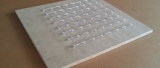
In this step, you need to take an empty cardboard box and stick white paper on its top as shown in the picture. White paper will be needed for precise positioning of the points.
After that, take a pencil and a ruler and mark 9 points on the paper every 2 cm thus forming a cube structure as shown in the picture.
We use a distance of 2 cm here because the length of the negative contacts of the LEDs is 2.5 cm. That is, in this case we will have 5 mm for soldering one LED to another. If we choose a larger distance, then soldering may become a problem; with a smaller distance, the cube will look somewhat awkward. Therefore, 2 cm will be the most suitable distance in this case.
After this, take any pointed object, such as a pen or pencil, and make a hole at each point. The holes should be of such a size that they hold the LED firmly enough - they should not be too small (the LED will not fit into them or we will not be able to wiggle it while soldering) or too large (the LED will fall into them). Therefore, check each hole made using an LED.
Step 4.
After that, place one LED in the hole and bend its positive terminal as shown in the picture below.
After this, bend the positive terminal of the LED again so that it forms an 'L' shape. If you look closely at the LED pin, you can see a small indentation where it should be bent into an 'L' shape. After this, bend the negative terminal of the LED to the right as shown in the following figure.
Step 5.
Then repeat all these steps for the remaining two LEDs and arrange these 3 LEDs in a row shape as shown in the picture. This template will be used for all the other LEDs in the cube. You can even bend the leads of all 27 cube LEDs first, and only then arrange them and solder their ends.
But first, let's repeat the described procedure for 9 LEDs, which we will arrange in the form of a matrix as shown in the figure.
Step 6.
After this, solder all the negative terminals of the LEDs as shown in the figure. Three LEDs will form a row.
After that, take two bare conductors 7 cm long (we prepared them earlier), place them as shown in the picture and solder 6 ends of these LEDs to form a complete matrix.
Now all the negative pins of the 9 LEDs are connected to each other, that is, we will have 9 positive pins (CP1-CP9) and one negative pin (CN1). After we take this structure out of the holes in the cardboard and cut off the protruding ends we will get one layer of our LED cube as shown in the following picture.
Step 7
We must take a similar sequence of actions to make the other two layers of the cube, the appearance of these constructed two layers is shown in the following figure.
Step 8
Now that we have all 3 layers of the cube, we need to join them together to create a cube.
After this, we attach the remaining 3rd layer to the resulting structure and we will have a complete cube. Soldering the 3rd layer will be a little more difficult than soldering the 2nd to the first, so try to do it carefully so as not to break the structure.
When soldering this entire structure, keep in mind that you should not heat (touch) the lead of the LED with a soldering iron for more than 5 seconds, otherwise you can overheat the LED and it will fail - and replacing it in an already made (at least partially) cube structure will not be easy.
DIY glowing balls, ideas with explanations and photos
There are several options for how to make a ball:
- Try to make a uniform and neat ball from the wire so that it has the same number of edges on which the LED strip will be attached.
- Use thin wire mesh, which is usually used to fence aviaries or chicken coops.
Let's look at the last option in detail, because, in our opinion, it is simpler and the result is more accurate:
- First, prepare the necessary material and tools for work (mesh, several garlands, pliers with wire cutters and a tape measure and gloves):
- Cut a square from the mesh, fold it into an envelope and twist all the parts so that they do not come apart from each other:
- Those places where sharp pieces of the mesh remain must be screwed to the mesh itself so that you do not get hurt during the work:
- Attach a garland to the finished ball by wrapping it around each element of the metal ball:
Program source code
In the resulting cube, if we want to turn on one LED, for example, the LED in the second column of the first layer, we will need to power the CP2 pin and apply ground to the CN1 pin. According to the connections made in the circuit, we need to apply a high level voltage to PIN3 of the Arduino (which is connected to CP2) and a low level voltage to PIN A0 (which is connected to CN1).
We can light any other LED in the same way. Further in the program, in an endless loop, we will light all the LEDs in our cube one by one.
void setup() for (int i=0;i pinMode(i,OUTPUT); // pins S0-10 are set to data output mode > pinMode(A0,OUTPUT); //PIN A0 is set to data output pinMode(A1, OUTPUT); // PIN A1 is set to data output pinMode(A2,OUTPUT); // PIN A2 is set to data output
digitalWrite(A0,HIGH); //apply logical “1” to A0 pin digitalWrite(A1,HIGH); // apply logical “1” to A1 pin digitalWrite(A2,HIGH); // apply logic "1" to A2 pin /* add setup code here, setup code runs once when the processor starts */ > void loop() digitalWrite(A0,LOW); // ground is applied to layer 1 of the cube for (int i=2;i digitalWrite(i,HIGH); // turn on each LED in layer 1 one by one delay(200); delay(200); delay(200); digitalWrite(i ,LOW); > digitalWrite(A0,HIGH); // logical “1” is applied to layer 1 of the cube
digitalWrite(A1,LOW); // ground is applied to layer 2 of the cube for (int i=2;i digitalWrite(i,HIGH); // turn on each LED in layer 2 one by one delay(200); delay(200); delay(200); digitalWrite(i ,LOW); > digitalWrite(A1,HIGH); // logical “1” is applied to layer 2 of the cube
digitalWrite(A2,LOW); // ground is applied to layer 3 of the cube for (int i=2;i digitalWrite(i,HIGH); // turn on each LED in layer 3 one by one delay(200); delay(200); delay(200); digitalWrite(i ,LOW); > digitalWrite(A2,HIGH); // logical “1” is applied to layer 3 of the cube >
LED cube 4x4x4
I present a project of a 3D LED Cube with a 4x4x4 matrix.
64 LEDs form a cube with sides 4x4x4, which is controlled by an Atmel Atmega16 microcontroller. Each LED has its own virtual address and can be controlled individually from a microcontroller, thus allowing you to achieve amazing effects.
See the video of the cube in action below:
Step 1. What do we need?
The first thing is the patience to solder all 64 LEDs together