Finally, I was discharged from the hospital, and before I had time to come to my senses, an acquaintance immediately approached me with a request to make the speaker from the PC beep. He said that he wanted to put a tweeter in his multimeter, but the problem is that when voltage is simply applied to the speaker, it remains silent like a guerrilla. Why does he need this and why doesn’t he buy a normal multimeter, I didn’t ask, let him do what he wants with it, and at least I’ll stretch my hands.
As has already become clear, if you apply direct constant voltage to the speaker, it will not squeak at all. This is understandable, this is an ordinary small speaker, but due to the very low sound quality it was nicknamed a tweeter. To make it produce sound, you need to apply not direct voltage, but high-frequency pulses.
I went online with this question.
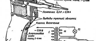
On YouTube I found a simple frequency generator circuit. Here she is.
As usual, I dug transistors out of my trash, they turned out to be s8050 and bc327-25. I didn’t worry about the capacitor and set it to 0.015 rather than 0.022, because we still have a trimming resistor in front of it, which is what adjusts the pulse frequency. I powered this thing from a 5 volt power supply through a 910 Ohm resistor and...
Still the same treacherous silence, I immediately began to blame the fact that I powered it incorrectly, but the battery also had zero effect, then on the transistors, I even assembled everything anew but with KT815 and KT814, and still achieved nothing.
And then comes the mysticism. I stuck to the circuit for about 15 minutes, and with my knowledge (I’ll ask experienced people to explain), I thought why the plus goes to the emitter if, in fact, it should serve as an output, and I simply switched the contacts between the emitter and collector. And immediately I heard a familiar squeak. I still can’t understand why this is so, because my last post had a similar circuit, but I didn’t touch the transistors there.
Photo of what came out
Power is supplied to the red and black wires.
I hope there is someone who will be helped by this scheme, because the search engine gives similar solutions with microcontrollers, which are not always easy to find. And here, as they say, we cobbled it together from what we had. And everything works. The application of this scheme can be very diverse; when I was looking for how to do this, I came across a person who wanted to attach a tweeter to a kettle.
A little off topic.
My next post will be a complete circuit of a gauss gun along with a capacitor charge indicator. Naturally, everything is simplified to the maximum (I don’t know any other way).
I often have fun at home. I recently saw a post about the Felix computer, and inspired by it, I decided to upgrade my own. If anyone is interested, I can also show you and tell you in detail. And so, that's all for today. I will also be glad to receive constructive criticism and answer your questions if possible.
The Arduino tweeter, which is often also called a buzzer, piezo speaker or even buzzer, is a frequent guest in DIY projects. This simple electronic component connects easily to Arduino boards, so you can quickly make your circuit make the sounds you want - beeping, beeping, or playing a decent tune. In this article we will talk about the difference between active and passive buzzers, analyze the diagram for connecting the piezoelectric element to the Arduino board, and show an example sketch for controlling a buzzer. You will also find an example of a melody that you can use for your project.
Description and operation diagram of the buzzer
Buzzer, piezo tweeter - all these are names of one device. These modules are used for sound notification in those devices and systems that require a sound signal to function. Buzzers are widespread in various household appliances and toys that use electronic boards. Piezo beepers convert commands based on the two-bit number system of 1 and 0 into audio signals.
Piezoelectric element “squeaker”
The piezo tweeter is structurally represented by a metal plate coated with a coating of conductive ceramics. The plate and the coating act as contacts. The device is polar, has its own “+” and “-”. The operating principle of the buzzer is based on the piezoelectric effect discovered by the Curie brothers at the end of the nineteenth century. According to him, when electricity is applied to the buzzer, it begins to deform. In this case, impacts occur on a metal plate, which produces “noise” of the required frequency.
Differences between active and passive buzzer
The main difference between an active buzzer and a passive one is that an active buzzer generates sound on its own. To do this, the user must simply turn it on or off, in other words, by applying voltage to the contacts or de-energizing it. A passive buzzer requires a signal source that will set the parameters of the sound signal. An Arduino board can serve as such a source. An active buzzer will produce a louder beep than its competitor. The frequency of the emitted sound of the active buzzer is 2.5 kHz +/- 300Hz. The supply voltage for the tweeter varies from 3.5 to 5 V.
An active piezo emitter is also preferable because the sketch does not need to create an additional piece of code with a delay that affects the workflow. Also, to determine what kind of element is in front of the user, you can measure the resistance between two wires. Higher values will indicate an active Arduino buzzer.
The tweeters do not differ in any way in their geometric shape, and it is not possible to attribute an element to one type or another based on this characteristic. Visually, the buzzer can be identified as active if there is a resistor and an amplifier on the board. In a passive buzzer, there is only a small piezoelectric element on the board.
Reply to the post “I wouldn’t want to see this at night”
I don’t know what to call it correctly, a response to a post, or a response to my own comment. #comment_175930757 I wouldn't want to see this at night
But comrade @stich02 poked my nose at me and asked me to make a swing and make a post. Although I don't see the point in this. But what is promised must be fulfilled. But suddenly you like the idea of what to do with your child (or yourself) in bad weather.
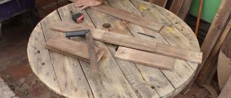
For the purity of the experiment, I bought a rail and a pipe. But you can make it with what you have. I made the first swing from the stuff that was there. 4 meters of 40*20 slats (one and a half meters left) and 1 meter of pipe for hot water cost 96 hryvnia. Or approximately 254 rubles. I did everything literally on my knees, in the corridor. And there is nothing complicated about it.
I will make the size of the swing 35*25cm. Because I just wanted it that way. Yes, even a small adult can fit in. Sometimes I do something with a child, and there are traces of help on the ruler. We mark, cut and make 5 more pieces along it. There should be a total of 6 slats.
These will be longitudinal and limiters.
Then he takes the hot water pipe. Why for hot. It is stronger due to the metal core. Cut 4 pieces of 20cm each. So that with a reserve.
We remember that we need 4 slats and finish the rest. This is what the swing will look like. Top and bottom respectively. My cord is 5mm and has a breaking strength of 250kg. The child will definitely survive. So we make the holes 7mm. On both edges of two long planks we mark the width of the plank
And mark the middle.
We drill holes and start sanding. The main thing is to go to the toilet before sanding. Because the grinder vibrates a lot. If then, you will have an unexpected result.
During the sanding process, we remember that we need to make more holes in 2 short and 2 long planks for the top. We secure it with bolts to maintain symmetry. And we assemble it with self-tapping screws
The swing hangs on the door frame with two of these things. Unfortunately, I don’t know their name. One of these can support me, 90kg. If you have a new type of door, then it is better to have two jambs, put something massive under the jamb, a crowbar, for example, a beam or a holder from a shovel, and hang a swing on it. Or directly to the ceiling, on the anchor.
This is what she will look like
We thread the cord through the bottom.
Then the front and back.
And now I’ll show you how to make the most important knot in life. Os̶o̶b̶e̶n̶n̶o̶ ̶v̶ ̶e̶yo̶ ̶k̶o̶n̶ts̶e̶
We tie one end of each piece of cord to a carabiner.
Ready. We spent two hours making the swing, another half a day cleaning the apartment, and 250 rubles for materials. The front and rear bars act as limiters. And the child can be placed and taken out from any side. The cord is not secured at the bottom, it is simply threaded through the holes so that you can make a slight tilt if desired.
Since I already have a swing. These were done in order to finish the post. To do this, I made the height with a reserve and attached only one side to the carabiner. Who needs a free swing? I will ship within Ukraine.
Well, to make this post useful, I’ll tell you about one life hack.
For more than ten years now, not in the summer, I have been wearing ankle boots. And good laces on them are like Chinese sneakers. I use a cord, only thinner than with a swing. But the tip is frustrating. Or when the eglet comes off on your sneakers. And after two weeks you have a tassel, not laces. (This is a plastic or steel tip on laces, yeah, I Googled it on purpose.) I found a way out. Heat-shrink tubing. It costs two rubles per bucket and it works. There are even different colors. Cut the heat shrink tube to the required length, put it on a cord and warm it up with a lighter. Ready.
Hi all! I’ve been reading the pica for a long time, but only now I decided to post something.
For a long time now, my husband has been asking me to make him a cover for his passport, but no one has gotten around to it. And then we got there, and in the end I got my hands on something like this. It was only the second time I worked with leather on my own (the first was an indistinct bracelet with a button with perforation). I cut out the blanks according to the pattern from a piece of black leather, covered them with a thin layer of red acrylic paint, depicted the emblem of the horde using an ancient Soviet burner and sewed them together with nylon thread. I didn’t take any photos of the process because I was overwhelmed with inspiration and didn’t even remember about the photo at that moment. Material: leather, nylon thread, acrylic paint. Tools: tapestry needle, scissors, punch (without any steps, makes only one hole, so everything had to be measured and marked by hand under a ruler), crooked hands and great enthusiasm.
I would be grateful for criticism and advice, as I enjoyed working with leather.
Buzzer connections to Arduino
Connecting the piezo element module to Arduino looks quite simple. The current consumption is small, so you can simply connect directly to the desired pin.
Connecting the tweeter to Arduino (port 12)
The electrical diagram for connecting a piezoelectric element without accompanying modules is as follows.
Buzzer connection diagram
On some versions of the buzzer housing you can find a hole for fixing the board with a screw.
The arduino buzzer has two outputs. You should pay attention to their polarity. The dark wire should be connected to ground, the red wire to the digital pin with PWM. One output is configured in the program as an “input”. Arduino monitors voltage fluctuations on the pin, which receives voltage from the button, resistor and sensors.
Arudino tweeter with contact names
The voltage at the “input” is supplied with different values; the system clearly records only two states – the above-mentioned 1 and 0 (logical zero and one). A logic one will refer to a voltage of 2.3-5 V. The “output” mode is when the Arduino supplies a logical zero/one to the output. If we take the logical zero mode, the voltage here is so small that it is not enough to light the LED.
Connection diagram of the tweeter to Arduino
Please note that the inputs are quite sensitive to external noise of various kinds, so the piezo tweeter leg should be connected to the output through a resistor. This will put a high level of tension on the stem.
Sound alarm
The simplest are a bell or a rattle. The bell is often used at long distances on a spinning fishing rod.
Principle of operation
A set of fasteners in which, for example, a bell is attached to the top of a feeder. If it starts to peck, the top of the feeder, on which the alarm is attached, begins to oscillate and our device produces a sound.
The advantages include low cost, sensitivity to the slightest bites, and the ability to use over long distances.
Step-by-step manufacturing instructions
Would need:
- A flat spring about 20 cm long , you can take it from an old alarm clock or watch. It should be smooth, without errors.
- Aluminum wire 20 cm long.
- Plastic strip 20 cm long.
- Dye.
We make holes with different diameters on the sides of our spring. We fasten the plastic strip on one side with wire so that it holds securely against the passage ring. On the other side we make a hook that holds the spring.
Sound bite alarm
An example sketch for a piezoelectric dynamic
To “revive” the buzzer connected to the Arduino board, you will need Arduino IDE software, which can be downloaded from our website.
One of the easiest ways to make a beeper talk is to use the “analogwrite” function. But it is better to use the built-in functions. The “tone()” function is responsible for launching the sound notification; in parentheses, the user should specify the parameters of the sound frequency and input number, as well as time. To mute the sound, use the “noTone()” function.
Example sketch with tone() and noTone() functions
The example connection diagram looks like this:
Connecting the tweeter to pin 3 of Arduino
When you use the tone() function, the following restrictions apply.
The sketch for an active buzzer is extremely simple. Using digitalWrite() we set the value 1 to the port to which the tweeter is connected.
Sketch option for a buzzer without tone()
An example sketch for the option without the tone() function is shown in the image below. This code sets the frequency of sound activation once every two seconds.
Sketch example
For the device to operate correctly, you must set a PIN number and define it as an “output”. The analogWrite function takes a pin number and a level as arguments, which ranges from 0 to 255. This is because the Arduino PWM pins have an 8-bit DAC (Digital to Analog Converter). By changing this parameter, the user changes the volume of the buzzer by a small amount. To turn it off completely, set the port to “0”. It should be said that using the “analogwrite” function, the user will not be able to change the pitch of the sound. For the piezo emitter, the frequency will be determined to be 980 Hz. This value coincides with the operating frequency of PWM outputs on Arduino and analogue boards.
Examples of melodies for a buzzer
In order to diversify the work with the new project and add an “entertaining” element to it, users came up with the idea of setting a certain set of sound frequencies, making it consonant with some famous compositions from songs and films. A variety of sketches for such melodies can be found on the Internet. Let's give an example of a melody for a piezo tweeter for one of the most recognizable tracks “nokia tune” from the now legendary Nokia mobile phones. You can make the pitches.h file yourself by copying its contents as indicated in this article on the official website.
Sketch
When writing your own melodies, it will be useful to know the note frequencies and durations of intervals used in standard notation.
Note frequency for Arduino tweeter
Homemade dialer (probe) for home
To check the integrity of the electrical circuit, multimeters, indicators and various continuity tests are usually used. Each device has its own pros and cons.
A multimeter is certainly the most accurate, but it is expensive, you need to know how to use it, and it is more suitable for serious electronics repairs than for household use.
The indicator costs mere pennies, but is not reliable. Its use requires some experience. In addition, working with them involves human contact with live parts. And this is unacceptable for beginners.
The best solution for your home would be a homemade dialer. This device is easy to use and can be easily assembled on the knee.
Probe assembly
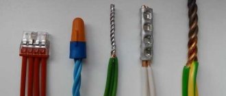
It is better to prepare everything you need in advance. The list of materials is short and includes:
2 markers, with an internal diameter of at least 10 mm.
5-10 cm of wire in insulation. Preferably copper. The section is selected experimentally based on the thickness of the marker tips.
Description and operation diagram of the buzzer
Buzzer, piezo tweeter - all these are names of one device. These modules are used for sound notification in those devices and systems that require a sound signal to function. Buzzers are widespread in various household appliances and toys that use electronic boards. Piezo beepers convert commands based on the two-bit number system of 1 and 0 into audio signals.
Piezoelectric element “squeaker”
The piezo tweeter is structurally represented by a metal plate coated with a coating of conductive ceramics. The plate and the coating act as contacts. The device is polar, has its own “+” and “-”. The operating principle of the buzzer is based on the piezoelectric effect discovered by the Curie brothers at the end of the nineteenth century. According to him, when electricity is applied to the buzzer, it begins to deform. In this case, impacts occur on a metal plate, which produces “noise” of the required frequency.
Piezodynamic tweeter device
You must also remember that there are two types of buzzer: active and passive. Their operating principle is the same, but the active one does not have the ability to change the sound frequency, although the sound itself is louder and the connection is simpler. More on this below.
Tweeter module for Arduino
Structurally, the module is available in a variety of options. The most recommended one for connecting to Arduino is a ready-made module with built-in wiring. Such modules can be easily purchased in online stores.
When compared with ordinary electromagnetic sound transducers, the piezo tweeter has a simpler design, which makes its use economically feasible. The frequency of the resulting sound is set by the user in the software (we present an example of a sketch below).
Differences between active and passive buzzer
The main difference between an active buzzer and a passive one is that an active buzzer generates sound on its own. To do this, the user must simply turn it on or off, in other words, by applying voltage to the contacts or de-energizing it. A passive buzzer requires a signal source that will set the parameters of the sound signal. An Arduino board can serve as such a source. An active buzzer will produce a louder beep than its competitor. The frequency of the emitted sound of the active buzzer is 2.5 kHz +/- 300Hz. The supply voltage for the tweeter varies from 3.5 to 5 V.
An active piezo emitter is also preferable because the sketch does not need to create an additional piece of code with a delay that affects the workflow. Also, to determine what kind of element is in front of the user, you can measure the resistance between two wires. Higher values will indicate an active Arduino buzzer.
Side warning light
Or, as experts say, lateral quivertype. The device is based on a fastening to the feeder form and a springy part made of plastic or metal. Placed between the coil and the first ring of the feeder.
How does it work
After casting, the line is threaded into the hook, which is located at the end opposite from the feeder. The length of the chassis is about 10-15 cm. We place the side quivertip to the feeder form at an angle of 90 degrees. When the bite starts, the device will become almost parallel to the feeder.
Important advantages are:
- works in any weather conditions;
- Suitable for use on the winding banks of reservoirs, where there are many cliffs and snags.
Since the bulk of quivertypes are made of fiberglass, the big disadvantage is its excessive softness, which means that in the case of a strong current its sensitivity is lost. Also, this material, even under light loads, can begin to delaminate.
How to make a quivertype
To make a quivertype at home you will need:
- 15-20 cm of metal spring wire;
- metal tube with a diameter of 2 mm and a length of 5 cm.
At a distance of 15 cm from the coil, we fix the tube on the feeder form. Next, we make a Z-shaped hook at one end of the wire, and bend the other at a right angle for fastening in the tube. We place the finished product on the feeder and throw it out. We insert the fishing line into the quiver tip hook. For better visibility, attach a bright colored ball to the end of the hook.
Side bite alarm for feeder
Buzzer connections to Arduino
Connecting the piezo element module to Arduino looks quite simple. The current consumption is small, so you can simply connect directly to the desired pin.
Connecting the tweeter to Arduino (port 12)
The electrical diagram for connecting a piezoelectric element without accompanying modules is as follows.
Buzzer connection diagram
On some versions of the buzzer housing you can find a hole for fixing the board with a screw.
The arduino buzzer has two outputs. You should pay attention to their polarity. The dark wire should be connected to ground, the red wire to the digital pin with PWM. One output is configured in the program as an “input”. Arduino monitors voltage fluctuations on the pin, which receives voltage from the button, resistor and sensors.
Arudino tweeter with contact names
The voltage at the “input” is supplied with different values; the system clearly records only two states – the above-mentioned 1 and 0 (logical zero and one). A logic one will refer to a voltage of 2.3-5 V. The “output” mode is when the Arduino supplies a logical zero/one to the output. If we take the logical zero mode, the voltage here is so small that it is not enough to light the LED.
Connection diagram of the tweeter to Arduino
Please note that the inputs are quite sensitive to external noise of various kinds, so the piezo tweeter leg should be connected to the output through a resistor. This will put a high level of tension on the stem.
An example sketch for a piezoelectric dynamic
To “revive” the buzzer connected to the Arduino board, you will need Arduino IDE software, which can be downloaded from our website.
One of the easiest ways to make a beeper talk is to use the “analogwrite” function. But it is better to use the built-in functions. The “tone()” function is responsible for launching the sound notification; in parentheses, the user should specify the parameters of the sound frequency and input number, as well as time. To mute the sound, use the “noTone()” function.
Example sketch with tone() and noTone() functions
The example connection diagram looks like this:
Connecting the tweeter to pin 3 of Arduino
When you use the tone() function, the following restrictions apply.
The sketch for an active buzzer is extremely simple. Using digitalWrite() we set the value 1 to the port to which the tweeter is connected.
Sketch option for a buzzer without tone()
An example sketch for the option without the tone() function is shown in the image below. This code sets the frequency of sound activation once every two seconds.
Sketch example
For the device to operate correctly, you must set a PIN number and define it as an “output”. The analogWrite function takes a pin number and a level as arguments, which ranges from 0 to 255. This is because the Arduino PWM pins have an 8-bit DAC (Digital to Analog Converter). By changing this parameter, the user changes the volume of the buzzer by a small amount. To turn it off completely, set the port to “0”. It should be said that using the “analogwrite” function, the user will not be able to change the pitch of the sound. For the piezo emitter, the frequency will be determined to be 980 Hz. This value coincides with the operating frequency of PWM outputs on Arduino and analogue boards.
Examples of melodies for a buzzer
In order to diversify the work with the new project and add an “entertaining” element to it, users came up with the idea of setting a certain set of sound frequencies, making it consonant with some famous compositions from songs and films. A variety of sketches for such melodies can be found on the Internet. Let's give an example of a melody for a piezo tweeter for one of the most recognizable tracks “nokia tune” from the now legendary Nokia mobile phones. You can make the pitches.h file yourself by copying its contents as indicated in this article on the official website.
Sketch
When writing your own melodies, it will be useful to know the note frequencies and durations of intervals used in standard notation.
Note frequency for Arduino tweeter
Float
Manufacturing instructions
To do this you need:
- Cut a ball with a diameter of 6-7 mm from a piece of foam plastic
- paint the top red or orange, the bottom blue
- make a hole in the center of the ball
- insert a beech rod into it, its thickness is up to 2 mm, length 6-7 mm
- paint the upper half of the rod with stripes of different colors
- put a figure eight on the bottom
- secure the fishing line
- Hang weights just above the hook (they will load half a ball of polystyrene foam into the water)