Schematic diagram of the memory for 6F22
The second version of the circuit on the same MAX712
Stabilization of the charging current is linear, there is no temperature measurement. The following assumptions were made when designing the charger:
- Powered by an unstable power source with a maximum voltage of 15 V.
- The charging current is 80 mA, that is, 0.5 C for batteries with a capacity of 160 mAh and 0.3 C for batteries with a capacity of 250 mAh.
- Charging batteries from 7 cells - that is, a total voltage of 9 volts.
Why 7 cans? The disposable battery has 6 cells of 1.5 V each. And the rechargeable battery has 7 with a nominal voltage of 1.2 V, which gives 8.4 V. Once fully charged, the voltage can be 10.5 V.
From the above data, the values obtained are R1 = 1.3 kOhm and Rsense = 3 Ohm. The power source must provide a voltage in any situation of at least 12 V (at least 1.5 V more than the voltage of fully charged cells). Heat dissipation per transistor: 0.7 W. Due to the accepted charging current, the fast charging time was limited to 3 hours. Instead of 2N6109, BD244C was used.
Useful: Cyclic timer for 220 V
We charge the Crown at home
The Krona is a 9-volt battery, which in principle is dangerous to charge, but rechargeable models are also being produced at the moment. Such a crown itself is an assembly of 7 batteries of the nickel-metal hydride type, standard 4a, connected in series.
It is very important that the charge for the crown should not be more than 30 milliamps.
As has already been revealed, batteries can be primary, that is, disposable, and secondary, that is, those that can be charged.
Secondary batteries are called rechargeable batteries; they differ in the chemical reagent they contain:
The easiest way to charge such batteries is to charge using a charger. To do this, you need to purchase a device that matches your battery. So, if your battery is a NiMH AA battery and its specification is 2650 mAh, then the charger should be of the same type and have a high charging speed. The charging time is affected by the capacity of the battery itself; usually this time is even specified in the instructions.
In most cases, batteries are equipped with charging indicators, so there is no need to time them. Still, you should not leave the battery connected to the charger for a long time, as this may have a bad effect on the capacity of the batteries themselves.
List of 9V charger elements
- R1 – 1.3 kOhm
- R2 – 150 Ohm
- R3 – 68 kOhm
- R4 – 22 kOhm
- R5 – 560 Ohm
- Rsense – 3 Ohm
- C1 – 1 µF
- C2, C4 – 10 nF
- C3, C5 – 10 µF
- T1 – BD244C
- D1 – 1N4007
- D2 – LED
- U1–MAX712
As it turns out, the LED connected between FASTCHG and the 470 ohm V+ resistor barely lights up. Ultimately, we connected the 560 Ohm resistor not to V+ (where it is less than 5 V), but only to the + power supply.
When the battery was charged for the first time, the fast charging process lasted only 2 hours and 8 minutes, and the actual charging current was 75 mA. Therefore, a 250 mAh battery cannot be fully charged. It follows that either the battery was partially charged, or the charger detected a state of charge at an early stage - the latter was so high that the power supply that was being used was producing 11.7 volts instead of the required 12 volts.
In principle, the voltage of the internal cells after charging can be even more than 1.5 volts, which further increases the power requirements. Part of the surface of the printed circuit board serves as a heat sink for the transistor.
During operation, the elements did not heat up enough to be perceived as hot. This is probably due to the relatively low charging current and relatively low supply voltage. Naturally, if desired, this charger can also be powered from the car's cigarette lighter.
DIY charger for Krona
In general, there are a lot of circuits for such chargers. This article presents a simple and affordable option that will help you make a charger for Krona while saving money and effort. The proposed circuit based on charging for a mobile phone allows you to make a device with your own hands. The author of the video is blogger Aka Kasyan.
By the way, a 9-volt battery is called Krona only in Russia and other countries that came from the USSR. In the world it is known as standard 6 f 22. Krona owes its name to a simple battery of the same standard, which was produced in the USSR.
Everything you need to assemble the device can be found in this Chinese store. Please note products with free shipping.
Products for inventors Link to the store.
The battery crown is an assembly of series-connected batteries, a rather rare 4a standard. In general, there are 7 of them. Typically this is a nickel metal hydride type.
DIY electronics in a Chinese store.
Charging schemes for battery Krona
It is recommended to charge the battery crown with a current of no more than 20 - 30 milliamps. It is recommended not to increase the current above 40 milliamps under any circumstances. The charger circuit is relatively simple and is based on a Chinese mobile phone charger. Cheap Chinese chargers come in two main types. Both, as a rule, are pulsed and implemented using self-oscillator circuits. The output provides a voltage of about 5 volts.
First type of charger
The first variety is the most popular. There is no control of the output voltage, but it can be changed by selecting a zener diode, which, as a rule, in such circuits are located in the input circuit. The zener diode is most often 4.7 - 5.1 volts. To charge the crown we need to have a voltage of about 10 volts. Therefore, we replace the zener diode with another one with the required voltage. It is also recommended to replace the electrolytic capacitor at the charger output. We replace it with 16 - 25 volts. Capacity from 47 to 220 microfarads.
Second type of charging
The second type - the circuit for charging mobile phones is a self-oscillator circuit, but with control of the output voltage through an optocoupler and a zener diode. In such circuits, either a regular zener diode or an adjustable one, like tl431, can be used as a controlling element. In this case, the most common zener diode is 4.7 volts.
The video shows a modification method based on circuit 2. First we remove everything that is after the transformer, except for the output voltage control unit. This is an optocoupler, a zener diode and two resistors. We also replace the diode rectifier. We replace the existing diode with fr107 (an excellent budget option).
We also replace the output electrolyte with high voltage. We select a 10 volt zener diode. As a result, charging began to output the voltage required for our purposes.
After remaking the charger, we assemble a current stabilization unit based on the lm317 microcircuit.
In principle, for such insignificant currents you can do without a microcircuit. Instead, install one quenching resistor, but preferably good stabilization. Still, the battery crown is not a cheap type of battery. The stabilization current will depend on the resistance of resistor r1; the calculation program for this microcircuit can be found on the Internet.
This scheme works very simply. The LED will light up when the output is loaded. In this case, Krona, since there is a voltage drop across resistor r2. As the battery charges, the current in the circuit will drop and at one point the voltage drop across each resistor will be insufficient. The LED will simply go out. This will be at the end of the charging process, when the voltage on the Krona is equal to the voltage at the output of the charger. Consequently, further charging process will become impossible. In other words, an almost automatic principle.
You don’t have to worry about Krona, since the current at the end of the charging process is almost zero. There is no point in installing the lm317t microcircuit on a radiator due to the scanty charging current. It won't heat up at all.
In the end, all that remains is to attach a connector for the Crown to the output of the charger, which can be made from the second non-working Crown. And, of course, think about the housing for the device.
Charging for Krona from a dc-dc converter
If you take a small dc-dc converter board, then you can easily make USB charging for the crown. The converter module will increase the voltage of the USB port to the required 10-11 volts. And then along the circuit there is a current stabilizer on lm317 and that’s it.
Crown battery device
Basic information on this issue can be read in the article what the crown battery consists of. It examines what is inside the crown in cross-section and much more. Unlike most batteries, the polarity of the crown is located on one side. If you don’t know where the crown cr 9v is plus and minus, then look at the picture.
How to disassemble the crown?
The Kronov battery can be disassembled quite easily. All you need to do is remove the label and bend the tin casing. Well, then all the insides will appear before your eyes. Before disassembling, arm yourself with scissors or a knife and pliers! Let's wake up this beauty!
First of all, remove the label. To do this, insert a sharp object like scissors into any convenient place and actually get rid of the sticker. Now let's deal with the tin body. We need to take it down. We look for a gap and use scissors and pliers to remove the body. After this, the battery will appear before us in disassembled form.
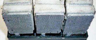
That's actually what's inside the battery. As you can see, it consists of 6 flattened elements connected to each other. Inside each of them there is a rod, an electrolyte and various chemical elements.
This analysis is complete!
Krona battery 9v
We will classify these elements according to their chemical composition and brand. We will also list what digital markings it is hidden under. Today there are the following brands of this power source:
- G.P.
- Duracell
- Space
- Energizer or Energizer
- Trophy
- Neda 1604 9v
- Camelion
- Pleomax
- Varta
- Robiton
- Panasonic
- Toshiba
As you can see from the list, many companies are engaged in the production of Krona batteries. Based on their chemical composition, the following types can be distinguished: Alkaline or alkaline crowns. Their main feature is their long service life and high price. Withstand heavy loads. Salt manganese-zinc . These power supplies were produced back in the 19th century. After some time, they were completely replaced by salt elements. The electrolytes are ammonium chloride solution. Lithium iron disulfide. Available with a solid positive electrode. Made from pyrite. Able to work perfectly at temperatures of minus 40 degrees. Air-zinc. They work when zinc is oxidized by oxygen. They have a large capacity and are quite environmentally friendly. Manganese-casting . The electrode is made of manganese dioxide. As a result, after the completion of the chemical reaction, lithium oxide is formed. Lithium thionyl chloride . Work in extreme temperature conditions. Due to this, they are often used by the military and scientists. Krona-type rechargeable batteries The main difference between such batteries and conventional ones is multiple recharges. Charging is carried out through a special device. Lithium ion or Li- ION . Quite efficient batteries with high performance. The capacity of such elements reaches 700 milliampere hours. They work best at room temperature. Nickel cadmium Ni-Cd batteries have a capacity of 120 mAh. They can be recharged up to 1000 times. The cost is quite low. Metal hydride elements NI- MN . Capacity 170 – 300. Safe, without metal impurities. Li- Po. These energy sources are the latest development of scientists. They work on the basis of pulse conversion. You can recharge from any source where there is 5 volts. Therefore, they can be easily recharged from a computer. A 9V crown battery on the case may have the following markings: MX1604, MN1604, 1604A, 6LR61, 6LF22, AM6, E-Block, PP3, 9V Brick Battery, 1604, 6R61, 6F22. Battery cell 7D-0.125 (7D-0.1, 7D-0.11).
How to make a crown charger
Among the many schemes for assembling chargers for Krona batteries, I found one that was relatively simple and affordable. By the way, the 9-volt battery, known in Russia and the CIS countries as “Krona,” has a 6F22 standard.
The battery consists of 7 4A nickel-metal hydride batteries connected in series. The recommended charging current is no more than 20-30 mA.
The charger is manufactured by redesigning a Chinese-made mobile phone charger.
There are 2 types of inexpensive chargers originating from China. They are pulsed, and both are based on self-oscillator circuits capable of delivering 5 V output.
The first type is the most common. It does not have control of the output voltage, but by selecting a zener diode, which is located in such circuits in the input circuit near the 1N4148 diode, you can obtain the desired voltage. Usually there are two types - 4.7 and 5.1 V.
To charge the Krona you need a voltage of about 10-11 V. This can be achieved by replacing the zener diode with one that has the appropriate voltage. It is also recommended to change the capacitor, which is located at the charging output. As a rule, it is 10 V. You need to install a 16-25 V capacitor with a capacity of 47-220 μF.
The second type of such circuits has control of the output voltage, implemented by installing an optocoupler and a zener diode.
Take a look at the principle of redesigning the second circuit.
It is necessary to remove all components located after the transformer, and leave only the unit that controls the output voltage. This unit consists of an optocoupler, a pair of resistors and a zener diode.
It is necessary to replace the diode rectifier, since manufacturers claim a charging current of 500 mA, and the maximum diode current is no more than 200 mA, although the peak current is about 450 mA. It's dangerous! In general, you need to install the FR107 diode. Thus, charging will produce the required voltage.
The next thing to do is to assemble a current stabilization unit, using the LM317 microcircuit as a basis. In general, you can get by with one quenching resistor instead of assembling a stabilization unit.
But in this example, preference is given to reliable stabilization, because the Krona battery is not the cheapest.
Resistor R1 affects the stabilization current. The calculation program can be downloaded in the Attached files at the end of the article.
How to charge Krona at home (video)
Thus, not all batteries can be charged, especially finger batteries. Rechargeable batteries are called rechargeable batteries and they can be recharged in several ways: using a special charger or at home using microcircuits.
Let's consider a device for charging low-power 9-volt batteries, type 15F8K. The circuit allows you to charge the battery with a constant current of about 12 mA, and when finished, it automatically turns off.
The charger has protection against short circuits in the load. The device is a simple current source, it additionally includes a reference voltage indicator on the LED and an automatic current shutdown circuit at the end of charging, which is made on a zener diode VD1, a voltage comparator on the op-amp and a switch on transistor VT1.