Quick release rip fence for DIY machines
Hello, dear readers and DIYers!
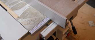
One of the most important design features for many different machine tools is the rip fence. Without it, it is impossible to perform a number of basic operations on circular, milling and band saw machines.
Of course, this device almost always comes complete with factory machines, but some machines can be made independently, the same applies to the rip fence.
In this article, the author of the YouTube channel “Crazy Workshop” will tell you how he made a quick-release version of such an emphasis.
This project is fairly easy to make but will require a small amount of welding.
Materials. — Steel profile pipes 20X20 40X40 mm — Bakelite wing nut M8 — Sheet plywood 25 mm thick — Steel stud M8, nuts, washers, angles — Compression spring, self-tapping screws — Aerosol enamel, PVA glue, sandpaper.
A layer of PVA glue is applied to the profile pipe, and a plywood piece is screwed to it. In this case, the author uses self-tapping screws with a conical head for countersunk.
Of course, before gluing these elements, you need to clean the frame with a flap disc, degrease and paint it to protect it from corrosion.
By tightening this nut, the movable “sponge” will be pressed, and the entire structure of the stop will work like a kind of long clamp, fixing on the edges of the table.
Of course, both edges of the table must be parallel to each other.
Of course, it requires several improvements. For example, a movable clamp should be made with a 100-150 mm guide, cutting a 35X35 mm profile pipe, which will be inserted into the frame with virtually no play.
A 20X20 mm pipe should be welded to such a guide, similar to a fixed stop.
Thus, the parallel stop will be fixed on both sides of the table with wide “jaws”, which will reduce the deviation of the stop plane from an angle of 90 degrees relative to the edge of the table.
I thank the author for implementing a simple design of a quick-release rip fence for machine tools.
Good mood, good health, and interesting ideas to everyone!
The author's video can be found here.
Source
Purpose of the clamping device for the machine
At first glance, modification of the woodworking machine is necessary only to fix the workpiece. However, with the correct choice of manufacturing scheme, the installed part can perform a number of other, no less important functions.
When processing wooden products, you can adjust their fixation manually. Ultimately, this affects the quality of the surface. This is especially true for thin strips, the thickness of which does not exceed 2-3 cm. Therefore, a do-it-yourself fixing device, after installation on the machine, should have the following functions:
Before starting design, it is recommended to familiarize yourself with similar factory models. To make the clamping mechanism with your own hands, scrap materials will be used. Therefore, when choosing the optimal design, it is necessary to be guided by the principle of expediency.
Experts do not recommend installing a fixing device for a jointer. This may affect the quality of the products.
Types of planing machines
The design of the clamping mechanism directly depends on the equipment model. Therefore, it is first necessary to carefully study the technical documentation, the features of the machine elements, and their characteristics.
The most common option is a power unit (electric motor) that drives a cylindrical cutter head. Its upper part is located above the level of the support table. The latter can move relative to the cutting part in the vertical direction. In this way, the depth of processing of the wooden workpiece is adjusted. You can make a similar model with your own hands.
In addition to the woodworking machine described above, the following types of equipment are used for mass production:
- thicknesser with one cutting head;
- cycle. Installed on lines for assembling furniture, door and window structures;
- two, three and tetrahedral. Processing occurs in several planes at once, which increases productivity;
- models with several knives.
Almost all modern equipment has clamps. The exceptions are machines made by yourself or old models.
When choosing a retainer design, you should pay attention to the equipment configuration. After its installation, the operational and technical qualities should not deteriorate.
Homemade clamp: option No. 1
Most often, for the manufacture of the above-described design, a part from an old washing machine is taken as a basis, and in particular, rollers for squeezing out moisture. In some cases, after minor modifications, the add-on can be installed on the equipment.
The frame consists of four support legs, which are connected to each other by a U-shaped profile. Locking shafts are installed on it. The profiles are not fixed to the base, but move freely along them. At the top of the structure there is a locking bar connected to the adjustment handle by a worm gear. For shock absorption, you can install springs that will partially compensate for the strong pressure when processing uneven surfaces.
The structure consists of the following components.
Using the top handle, you can adjust the degree of pressure. The disadvantage of this model is its large massiveness. It may not be suitable for all types of machines.
To reduce the labor intensity of manufacturing a mechanism for a planer, you can use the rollers of a washing machine. They need to be trimmed first.
Thicknessing machines for wood
Any craftsman needs instructions on how to make devices such as homemade thickness planers for wood. Making this mechanism is not very difficult. The first thing you need to do is take a sheet of plywood 500 m long and 400 mm wide, with a thickness of at least 15 mm. It will serve as the basis for the future device. Then stands for the electric planer are made from another piece of plywood of the same thickness and attached to the base. They are secured with screws to the back of the plywood sheet. An electric planer is also installed there.
Then a platform is installed under the surface planer, in the center of which a hole must be made. This hole is cut with a jigsaw directly in the shape of the electrical appliance, and the device itself is secured to it with screws.
Next, the drive mechanism is assembled and placed on the main platform. With his help, she lowers and rises. In each of the four corners of the base, on which the electric planer is already installed, screws with large threads are mounted. With their help, you can adjust the thickness of the material being processed.
Homemade clamp: option No. 2
An alternative option for making a machine clamp with your own hands is a slight modification of the equipment. It consists of installing two slats on the sides of the frame. Two bearings are installed in the main working shaft, through which a fixing axis passes.
The difficulty may lie in the configuration of the bed. All models have smooth edges to allow mounting of eyelets. The degree of clamping is adjusted using a spring. It moves along the slats, thereby changing the pressure on the workpiece.
Types of planing machines
The design of the clamping mechanism directly depends on the equipment model. Therefore, it is first necessary to carefully study the technical documentation, the features of the machine elements, and their characteristics.
The most common option is a power unit (electric motor) that drives a cylindrical cutter head. Its upper part is located above the level of the support table. The latter can move relative to the cutting part in the vertical direction. In this way, the depth of processing of the wooden workpiece is adjusted. You can make a similar model with your own hands.
In addition to the woodworking machine described above, the following types of equipment are used for mass production:
- thicknesser with one cutting head;
- cycle. Installed on lines for assembling furniture, door and window structures;
- two, three and tetrahedral. Processing occurs in several planes at once, which increases productivity;
- models with several knives.
Almost all modern equipment has clamps. The exceptions are machines made by yourself or old models.
When choosing a retainer design, you should pay attention to the equipment configuration. After its installation, the operational and technical qualities should not deteriorate.
Homemade jointing machine: sketch, main manufacturing stages
For any work to be successful, you must have good equipment and tools. The same statement applies to amateurs (or professionals) “tinkering” with wood. Craftsmen who make furniture or other wooden products always try to acquire various tools and devices that can help them in their work.
For example, a jointer. This device significantly increases the productivity and quality of woodworking. But not all fans can purchase it, because its price is quite high. How to get out of such a difficult situation? There is a solution, and it’s quite simple - it’s to make a tabletop jointer with your own hands. And the manufacturing process itself will be discussed in the article.
Homemade surface planer from an electric planer
A wood jointing machine is made with your own hands from an electric planer; it is the main component of the tool. They plan the lumber directly with it. There is no need to worry about the performance of a hand-made mechanism - as practice shows, the quality of products does not decrease much when using such a machine, in comparison with purchased equipment.
First, you need to decide on the size of the parts that you plan to create on the future tool. In accordance with the selected dimensions, the dimensions of the machine itself are already selected. The width and height of the equipment body, the length of the pin, and the length of the thicknesser guides are determined.
What you will need to make a homemade surface planer with your own hands:
- Unoccupied manual electric planer.
- DIY drawings of a surface planer from an electric planer.
- Plywood and bars for assembling equipment casings, as material for assembling the casing.
- A small amount of free time.
It would be best to draw up your own drawing, focusing on the specific features of both the existing electric planer and the parts that will be made using a tabletop jointer. You can, of course, follow a ready-made drawing, but this is a more difficult task.
Studs and guides
Then you need to correctly determine the location of the pin with which the surface planer will rise and fall. The efficiency of the future machine in working on parts directly depends on how well it is located.
For example, you can place it in the very middle of the body of the instrument, which is done quite often by inexperienced craftsmen. But this is far from the best option, since it does not provide ease of use, and also does not provide reliable and easy fixation. Ideally, in order to avoid any particular difficulties when working with the tool, you need to place the pin between the front and rear handle of the tool.
To provide the pin with the necessary mobility, a rolling bearing is installed on the top cover of the surface planer, converted from a planer. A nut is installed on the middle plate - with its help, the height of the thicknesser becomes easily adjustable, with a small step and increased accuracy.
Machine guides contribute to efficiency and precision when machining workpieces. They are made from the most ordinary wooden blocks, which do not require too much money. They should be slightly longer in length than the part for which they are intended, that is, they should not be made directly along the length of the workpieces, but leave a small margin.
Among other things, the lower plane of the marking machine must be arranged so that during operation it can be parallel to its knives. This way it will be possible to achieve maximum accuracy when processing a particular part.
If it is under an electric planer, achieving this accuracy will not be so easy, and the effectiveness of the tool will not be as expected. But if everything is done correctly, machines designed according to this principle will delight the master.
Why do you need a jointer?
A woodworking shop can have a variety of machines, but the most commonly used (besides the circular saw, of course) are jointers and planers. These two types of units are slightly similar in their function, but differ in the method of use.
Thicknessing machines are available in both single-sided and double-sided types. In the first case, only one side of the workpiece is processed in one pass. A double-sided thickness planer is more productive. Here the output is an almost finished part.
Thicknessing machines have a shaft located above the tabletop. Moreover, the latter is made massive in order to smooth out large vibrations. In addition, the mechanism is equipped with a special casing, which is designed to dampen noise.
A jointer has a slightly different task. This device is used to create a smooth surface without significant roughness on the workpiece. This machine, like the previous version, is equipped with a shaft with knives, only in the jointer it is located under the table top.
The workpiece is fed onto the work surface from one side, and the output from the opposite side is already partially processed. This way, layer by layer, the desired evenness is achieved. After processing on a jointer, the part can be fed to a surface planer.
Manufacturing of the machine
To manufacture a thicknessing machine, several operations are carried out during which the work is performed:
- The base for the desktop is made of plywood (10-15 mm), 400x500 mm in size.
- The stands for the platform with the electric planer are being fixed. Plywood is used to make stands. The structure is assembled using screws and fixed to the base, followed by installation of an electric planer.
- A platform is cut out for mounting the electric planer. A plane is attached to the platform, taking into account a special hole cut exactly in the center, matching the size of the plane. For fastening, special strips are used, which are fixed with screws.
- Threaded screws with gears are mounted on the platform. A special mechanism is installed to raise and lower the platform. 4 screws are mounted at the corners of the base.
- The platform is mounted on ready-made stands and, together with the electric planer, is secured with screws. Electrical wiring is laid to power the plane, taking into account the possibility of preventing damage to the wiring when processing workpieces.
- The platform control handle with an electric planer is being installed.
- A bar with a scale and a special pointer are installed. A measuring bar is necessary for accurately measuring workpieces and maintaining specified dimensions.
After completing the assembly of the thickness planer, testing and adjustment are carried out. After work, the electric planer must undergo cleaning and lubrication of working parts.
Basic Concepts
Such equipment will have numerous rotating parts. From this we can conclude that making such a machine with your own hands will not be so easy. Therefore, when starting to manufacture it, you need to calculate your strength. If you already have some similar experience, then you will cope with the task. It is worth noting right away that you will not be able to make a jointing machine entirely from parts of your own making. Of course, it’s possible that you have a large assortment of different devices in your “bins,” but this rarely happens. First of all, this concerns the shaft with knives and bearings. They will most likely have to be purchased or even ordered. But if everything you need is available, then you can safely start designing.
Electric drive of the jointer
And of course, don’t forget about the drive. All mechanisms must rotate. This means that the drive will be the “heart” of the machine. Here are some recommendations for this design element: - first of all, prepare the electric motor.
Electric motor for jointer
It is best to use a three-phase unit for these purposes. Of course, in this case you may have to redo the electrical network in your workshop, but it will be worth it. Three-phase electric motors operating at a voltage of 380 V are capable of developing greater power. In addition, the torque of such devices is suitable for our purposes. The minimum power value should be 3 kW, but the maximum is at your discretion;
Be very careful about providing power to the machine. Three-phase current is supplied through a four-core cable. In this case, reliable grounding must be organized. These requirements will help avoid accidents when working on the machine.
Drawing. The main stages of creating a jointer
Tabletop jointer - drawing
Tabletop jointing machine - drawing (part 2)
A jointing machine, its simplest version without additional functions, can be made quite easily with your own hands. The general progress of work in this case will look like this:
When fastening, glue and clamp are used. The recess should ideally fit the dimensions of the bearing;
After creating the system for turning the electric motor on and off, the machine is ready for use. But in order for your new tool to bring only benefit and joy to work, it is worth using it correctly and safely.
Preparing the necessary accessories for work
In order to make a jointing machine yourself, you need a certain set of tools and materials. An example would be:
Manual electric planer. It is this tool that is used today as the basis
It is recommended to pay attention to products from Bosh and Makita - the products are of very high quality and can last for a long period. You will need a drill press with a variety of drill bits or an electric drill. They are used to make holes. Wood screws are fasteners that are very widespread today. Plywood is used as a common material in a wide variety of jobs.
In this case, chipboard can be called an undesirable option, since it is not suitable for such work. Solid wood is also required, which is used to create a side support. The thickness of the timber used varies within 15-20 mm.
This set can be called recommended, as it may differ significantly depending on the specific case.
