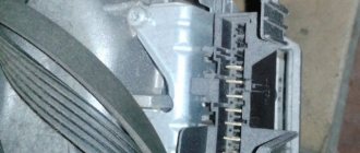
Definition and technical description.
* - automatic translation of part of the book.
It's a curiolls fact that you won't find the term "turbine" in most physics books.
The turbine jet produces axial pressure, accelerating the mass of air. When air masses are accelerated in a flow they create thrust. Forces are measured in Newtons, not kilograms and grams! A force of 1 Newton (denoted by the letter N) acts when a mass of 1 kg accelerates or decelerates by 1 m/s. The change in speed over a period of time is defined as acceleration and is measured in m/s.
In the encyclopedia, in the “turbine” section, it is written: “A POWERFUL ENGINE in which the energy of a moving medium (water, steam, gas) is converted into useful energy; another name is a turbojet engine . The predecessors were windmills and water wheels. Specialist technical books on this topic explain the various tour escapes in some detail under the main heading jet engine.
In Dubbel Engineering you will find the definition: “a gas turbine is a machine that uses heat to transfer mechanical energy (shaft power) or thrust (for example, aircraft engines)”, accordingly, the term gas turbines is a general term for all types of Turbo Jet engines. Jet turbines and turboprop engines. They are all considered “gas turbines; from aircraft modeling systems such as JPX. F.D. micro turbines. Turbomin and Pegasus, as well as KJ-66, .1-66 and TK-50 turbocharged engines feawred in this book, and including ING any such engine type that is either currently available or has not yet been invented. They are all “gas turbines” to create thrust!
In fact, an alternative and more appropriate name for such devices is aircraft model engines with turbocharged air jets. I prefer the term that is often used by specialists: “jet turbines”, some people call them jet engines. As you can see, we already have more than enough definition at our disposal. There is no need to come up with any new definitions. Unfortunately. technical experts do not always speak a language that is logically correct and clear. Of course, to aid the understanding of readers who do not have specialized knowledge, it is necessary to always indicate what exactly is meant by the word wrbines. These are blueprints for a turbojet engine .
Not a big example, the engine draws in air at a speed of 0.25 kg/second and accelerates it at the same time to a speed of 400 m/s static axial pressure - 100 N *
You can buy the turbojet engine using the link HERE. Delivery 7 - 15 days.
Drawings of an aircraft model turbojet engine.
The way I designed and built a homemade jet engine is not the best way to do it.
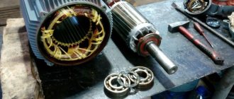
I can imagine a million ways and schemes to create a better model, more realistic, more reliable and easier to manufacture. But now I've put together one. Main parts of model jet engine:
- The DC motor is strong enough and at least 12 volts
- A DC source of at least 12 volts (depending on what kind of DC motor you have).
- A rheostat, the same one sold for adjusting the brightness of light bulbs.
- A gearbox with a flywheel is found in many car toys. It's best if the gear housing is made of metal because plastic can melt at such high speeds.
- A sheet of metal that can be cut to make fan blades.
- Ammeter or voltmeter.
- Potentiometer at approximately 50K.
- Electromagnet coil from a solenoid or any other source.
- 4 diodes.
- 2 or 4 permanent magnets.
- Cardboard to assemble a body similar to a jet engine body.
- Filler for car bodies, to create an exterior.
- Rigid wire to support everything. I usually use wires from cheap hangers. They are strong enough and flexible enough to be molded into the desired shape.
- Glue. I prefer hot glue for most parts, but pretty much any glue will do for now.
- White, silver and black paint.
Required Tools
To successfully assemble an engine with your own hands, you need to carefully prepare for this. First of all, you need to prepare a set of keys of various sizes. You may also need a universal gas wrench. In addition, you need a special tool for pressing in the piston pins and a torque wrench to correctly calculate the tightening torque of the bolts. Socket wrenches and socket heads are best suited for assembling the motor.
Many foreign-made internal combustion engine models have special bolts. To unscrew them you will need special keys, which can be found in stores that sell auto parts.
To remove large, heavy engines from the car body in the garage, you may need a crowbar to pry the engine from underneath and disconnect the transmission and clutch from it. To protect the vehicle's paintwork from possible mechanical damage during the process of repairing the power unit, cover the fenders and radiator of the vehicle with a thick cloth.
To remove and install the engine, a crane is usually used, and in its absence, a rope or a dense and strong cable.
When all the necessary tools are prepared for the upcoming work, you can learn how to assemble the engine of a scooter or any other vehicle.
Running in the car
After overhauling the engine, it should be properly run in. Otherwise, new malfunctions may occur, and resources will not be used up even by 50%. The simplest scheme for proper break-in is at idle. After starting, the engine warms up for 10 minutes at idle speed, and then turns off until it cools down. Repeat several times. This action allows you to identify malfunctions or unacceptable leaks.
The next method is to idle for about ten hours. In this case, you should sometimes check the condition of the car, stopping the engine every hour for a break. The coolant temperature should not exceed +80°C.
During break-in, new parts are worn in, and too much mileage will immediately cause harm. The average norm is two three thousand kilometers.
Important! Avoid extreme driving and speeding over 60 km/h.
What is a major overhaul and why is it needed?
Overhauling a VAZ engine is quite a labor-intensive job that requires knowledge of the structure and operating principle of the unit.
This process will take a lot of time. You will have to remove the engine from the car and completely disassemble it. All removed spare parts are checked for suitability for further use and, if necessary, replaced with new ones. Particular attention is paid to the crankshaft: it is restored and brought into perfect condition. The existing systems are also checked: cooling, lubrication, fuel supply, and the crank mechanism is repaired.
During repair work, internal combustion engine parts and components are brought to perfect condition. After assembling the unit, its condition and performance should be identical to a new engine just released from the assembly line. Capital is needed if the engine has fully or partially exhausted its service life, and corresponding signs have appeared indicating this. It is impossible not to pay attention to them. With further use of the car, the engine may completely fail and cannot be restored. There is only one option left - purchasing a new part. Naturally, purchasing spare parts is more expensive than repairing them.
The service life of the engine before overhaul can be extended if you follow simple rules when operating the machine.
- Monitor the oil level and change it regularly.
- Monitor the coolant level to prevent the machine from overheating.
- Fill with high-quality fuel recommended by the manufacturer.
- Operate the machine wisely and avoid overloading.
- Limit the vehicle's idling time to a minimum.
- Avoid extreme driving that requires high speeds. Do not allow the tachometer needle to enter the red zone.
Application
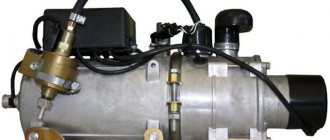
The turboshaft engine has also found application on the ground. It would even be more correct to say that it was on the ground that it was initially used, and only after the advent of aviation, as such, “moved” to the sky. It can be found both in transport and at various mainline stations, where it is usually used as an alternative to a diesel engine. Compared to a diesel engine, a turboprop engine is lighter in weight, less noisy and more powerful, if we take engines of the same size.
In industry and national economy
TVaD is successfully used as a natural gas supercharger at gas pumping stations. It can often be seen on large gas pipelines. One of the latest developments is the T16 gas turbine, with a capacity of 16 MW. A short video showing the use of a turboshaft engine in the electric power industry.
Basic indicators:
- 16.5 MW - shaft power.
- 37% - efficiency, mechanical drive.
- 36% - efficiency, electric (simple cycle).
- 80% - efficiency, combined production of electricity and heat
- 200,000 hours - full life cycle
- NOx emissions - no more than 25 ppm.
Turboshaft engines are used in mobile power plants to drive generators. Power plants with this engine occupy less volume than power plants with traditional engines.
In the transport sector
Although turboshaft engines are generally described as helicopter power plants, their use is not limited to them. Often the TVAD plays the role of an auxiliary unit rather than the main propulsion unit. Aircraft are usually equipped with such installations, and they are used to power the main systems of the vessel during its ground servicing. That is, when the plane is on the ground, it is not necessary to start its main engines to generate electricity or create pressure in the hydraulic systems; for this, it is enough to start such a small installation. TVaD is also used as a starting unit, which rotates the turbine rotor during startup. In this case, it is called a turbostarter.
The type of railway transport on which TVaD is installed is called a gas turbine locomotive. The principle of its operation is that a turboshaft engine rotates the shaft of a generator that produces electric current. The current is supplied to electric motors, which, in fact, are the main power plant. The history of gas turbine locomotives began in the 60s, when the first prototypes were designed, although they later gave way to the now more well-known electric locomotives. At the same time, since 2007, work on the creation of gas turbine locomotives has resumed, and even a test copy has been created that runs on liquefied gas. Its tests were successful, so in the near future, perhaps, it will be mass-produced.
The creators of military ground equipment did not ignore TVaD either. Some tanks, including the domestic T-80 and the American M1 Abrams, are equipped with TVaD. A short video of the development, implementation and use of a turboshaft engine on a tank.
Turboshaft engines are also used in watercraft called gas turbine ships.
These include hovercraft or hydrofoils. The most famous domestic gas turbine ship is the military vessel "Zubr" - the largest landing ship on an air cushion. This giant is known far beyond Russia and is the world record holder among hovercraft in terms of its dimensions. But somehow things didn’t work out with domestic passenger gas turbine ships. The Cyclone ship, designed in the 80s, did not survive the restructuring and was forgotten over time, and new passenger ships equipped with TVaD have not yet appeared. T-80 tank with gas turbine engine Landing craft "Zubr"
How to make a jet engine with your own hands
The simplest jet engine is a valveless pulsating unit. After its invention, it became obvious that it could propel a rocket even in vacuum. Due to the fact that turbojet engines began to be used everywhere, the development of this type of propulsion was suspended. But many amateurs continue to be interested, study and even assemble the unit themselves. Let's try to make a jet engine with our own hands.
Motor based on Lokved's patent
The device can be built of any size if the required proportions are strictly observed. A DIY jet engine will have no moving parts. It is capable of operating on any type of fuel if a device is provided for its evaporation before entering the combustion chamber. However, the start is made on gas, since this type of fuel is much more convenient than others. It’s easy to build the structure, and it won’t take much money. But you need to prepare for the fact that the jet engine will operate with a lot of noise.
I also install an evaporative atomizer for liquid fuel with my own hands. It is placed at the end of a metal pipe through which propane enters the combustion chamber. However, if you plan to use only gas, then installing this device is not necessary. You can simply run propane through a 4 mm diameter tube. It is attached to the combustion chamber using a ten millimeter fitting. Sometimes different tubes are also provided for propane, kerosene and diesel fuel.
At the start, gas enters the combustion chamber, and when the first spark occurs, the engine starts. It is not difficult to purchase cylinders today. Convenient is, for example, having eleven kilograms of fuel. If a large flow rate is expected, the reducer will not provide the necessary flow. Therefore, in such cases, simply install a needle valve. In this case, the cylinder cannot be completely emptied. Then there will be no fire in the tube.
It's alive!
After digging around on the Internet, I roughly understood what the problem was with the first engine. Due to the ramming, the fuel was distributed unevenly, cavities formed in it, and it was non-uniform, which is why the combustion process was very sluggish and instead of a rocket, a good smoke bomb was obtained. The solution to the problem was simple - pour boiled caramel fuel into the pipe. I took a metal bathroom rod as a body and decided to experiment with the proportions of fuel and with the addition of iron oxide 3 (that is, ordinary rust), because it was supposed to increase the burning rate.
Examples of pure caramel fuel and with added rust. Source
I made the engines smaller because I didn’t see the point in making a full-size version, just as I didn’t see the point in plugs and nozzles; they shouldn’t have affected the fuel burning rate, because all the subjects were in equal environmental conditions.
Before cooking fuel, let's talk about safety precautions, because caramel is highly flammable and burns very quickly. You should only cook fuel on an electric stove; you cannot cook fuel on a gas stove or any other source of open fire. By the way, in the recent explosion of a pyrotechnics warehouse in Beirut, according to official data, it was saltpeter that ignited, so be extremely careful when cooking.
Fuel was cooked on an electric stove in a pancake maker
until the color and consistency of condensed milk. The good thing about a pancake maker is that it heats all the ingredients evenly and doesn’t burn.
As a result, I got several test subjects:
- Engines with mortar-ground and boiled caramel fuel
- Engines with grinded and cooked caramel fuel
- Engines with grinded and cooked caramel fuel with the addition of 1% iron oxide 3
Now it was necessary to test the engines. The spoilers say the percentage of ingredients in the format Saltpeter/Sugar/Rust (if any), and inside there are gifs of the burns themselves.
Conclusions:
- This time all the engines caught fire and they burned very well, which of course made me happy
- Rust increases the rate of combustion. For comparison, the 55/45 engine burned for about 35 seconds, and the 54/45/1 for 26 seconds;
- Grinding in a coffee grinder did not significantly increase the burning rate
- Even with the replacement of sugar, there was still a lot of unburned substance in the engines (black and white substance in the “barrels” in the last photo), the composition of which was unknown
In general, the fuel caught fire, it remains to decide whether to make a rocket with it, or look for another solution.
Jet engine design
The jet engine was invented by Dr. Hans von Ohain , a prominent German design engineer, and Sir Frank Whittle . The first patent for a working gas turbine engine was obtained in 1930 by Frank Whittle. However, it was Ohain who assembled the first working model.
On August 2, 1939, the first jet aircraft, the He 178 (Heinkel 178), powered by the HeS 3 engine developed by Ohain, took to the skies.
The design of a jet engine is quite simple and at the same time extremely complex. Simply based on the principle of operation: outside air (in rocket engines - liquid oxygen) is sucked into the turbine, there it is mixed with fuel and burned, at the end of the turbine it forms the so-called. “working fluid” (jet stream), which moves the car.
It’s so simple, but in reality it’s a whole area of science, because in such engines the operating temperature reaches thousands of degrees Celsius. One of the most important problems of turbojet engine construction is the creation of non-melting parts from melting metals. But in order to understand the problems of designers and inventors, you must first study the fundamental structure of the engine in more detail.
Jet engine design
jet engine main parts
At the beginning of the turbine there is always a fan that sucks air from the external environment into the turbines. The fan has a large area and a huge number of specially shaped blades made of titanium. There are two main tasks - primary air intake and cooling of the entire engine as a whole, by pumping air between the outer shell of the engine and the internal parts. This cools the mixing and combustion chambers and prevents them from collapsing.
Immediately behind the fan there is a powerful compressor , which pumps air under high pressure into the combustion chamber.
The combustion chamber also acts as a carburetor, mixing fuel with air. After the fuel-air mixture is formed, it is ignited. During the combustion process, significant heating of the mixture and surrounding parts occurs, as well as volumetric expansion. In effect, a jet engine uses a controlled explosion to propel itself.
The combustion chamber of a jet engine is one of its hottest parts - it requires constant intensive cooling. But this is not enough. The temperature in it reaches 2700 degrees, so it is often made of ceramics.
After the combustion chamber, the burning fuel-air mixture is sent directly to the turbine.
The turbine consists of hundreds of blades on which the jet stream presses, causing the turbine to rotate. The turbine, in turn, rotates the shaft on which the fan and compressor “sit”. Thus, the system is closed and requires only a supply of fuel and air for its operation.
After the turbine, the flow is directed to the nozzle. The jet engine nozzle is the last but not the least part of a jet engine. It directly forms the jet stream. Cold air is directed into the nozzle, forced by the fan to cool the internal parts of the engine. This flow restricts the nozzle collar from the super-hot jet stream and causes it to melt.
Deflectable thrust vector
Jet engine nozzles come in a variety of different types. He considers the most advanced to be a movable nozzle mounted on engines with a deflectable thrust vector. It can compress and expand, and also deflect at significant angles, regulating and directly directing the jet stream . This makes aircraft with thrust vectoring engines very maneuverable, because maneuvering occurs not only thanks to the wing mechanisms, but also directly by the engine.
Supersonic ramjet engines
Supersonic ramjet engines are designed for flights in the speed range 1 < M < 5.
The deceleration of a supersonic gas flow is always discontinuous, and a shock wave is formed, which is called a shock wave. At the distance of the shock wave, the process of gas compression is not isentropic. Consequently, losses of mechanical energy are observed, the level of pressure increase in it is less than in an isentropic process. The more powerful the shock wave is, the more the flow velocity at the front changes, and accordingly, the greater the pressure loss, sometimes reaching 50%.
In order to minimize pressure losses, compression is organized not in one, but in several shock waves with lower intensity. After each of these jumps, a decrease in flow speed is observed, which remains supersonic. This is achieved if the front of the shocks is located at an angle to the direction of the flow velocity. The flow parameters remain constant in the intervals between jumps.
In the last jump, the speed reaches a subsonic level, further processes of braking and air compression occur continuously in the diffuser channel.
If the motor input device is located in the area of undisturbed flow (for example, in front of the aircraft at the nose end or at a sufficient distance from the fuselage on the wing console), it is asymmetrical and is equipped with a central body - a sharp long “cone” extending from the shell. The central body is designed to create oblique shock waves in the oncoming air flow, which provide compression and braking of the air until it enters a special channel of the inlet device. The presented input devices are called conical flow devices; the air inside them circulates, forming a conical shape.
The central conical body can be equipped with a mechanical drive, which allows it to move along the axis of the engine and optimize braking of the air flow at different flight speeds. These input devices are called adjustable.
When fixing the engine under the wing or below the fuselage, that is, in the area of aerodynamic influence of aircraft structural elements, input devices of a flat form of two-dimensional flow are used. They are not equipped with a central body and have a transverse rectangular section. They are also called mixed or internal compression devices, since external compression here occurs only during shock waves formed at the leading edge of the wing or the nose end of the aircraft. Adjustable input devices of rectangular cross-section are capable of changing the position of the wedges inside the channel.
In the supersonic speed range, ramjet engines are more efficient than in the subsonic speed range. For example, at flight speed M=3, the pressure increase ratio is 36.7, which is close to that of turbojet engines, and the calculated ideal efficiency reaches 64.3%. In practice, these indicators are lower, but at speeds in the range M = 3-5 SPVjet engines are more efficient than all existing types of VRE.
At a temperature of an undisturbed air flow of 273°K and an aircraft speed of M=5, the temperature of the working retarded body is 1638°K, at a speed of M=6 - 2238°K, and in a real flight, taking into account shock waves and the action of the friction force, it becomes even higher.
Further heating of the working fluid is problematic due to the thermal instability of the structural materials that make up the engine. Therefore, the maximum speed for a SPV jet is considered to be M=5.
Start
At first I didn’t dare to make a boat more than five meters long in a 6-meter-long garage: there was not enough space. However, the start was so sudden that there was no time to think for a long time.
The blockhead was going to be made from a block of wood and fiberboard. And I even brought the materials, but at the very last moment we made a choice in favor of drywall. They laid two sheets of chipboard on the floor in the garage, fastened them together and began making frames from a calibrated pine block 25 x 30 mm, according to the project data. But not as strong and reliable as in a real boat: their task is to withstand only the weight of drywall.
The block was sawed down at the required angles and fastened with plywood gussets, screwed with self-tapping screws. The location of the frames was drawn right on the chipboard and screwed into place in the required order. The stringers were made from long and narrow strips of plywood. Their function was the same as that of the frames - to support the weight of the drywall. Self-tapping screws were used everywhere for fastening.
The result is a surprisingly rigid system. And to make sure that everything was done correctly, they unscrewed the structure from the chipboard sheets, pulled it outside and inspected it from a distance.
The system was very light and resembled the Sever 420 boat, drawn in vector graphics. The result was very pleasing. The frame was attached to its original place. All this took a day or two.
I brought several sheets of ceiling plasterboard. The sheets were applied to the frame, marked with a pencil and the elements of the future blockhead were cut out. They were also attached to the frame with self-tapping screws.
Technology - youth 1951-07, page 39
it appears this way. A nail (6) 1-1.5 mm thick is inserted into one end of the film roll (1). Then the roll with the nail is tightly wrapped with thick paper (2) with foil (7) (chocolate or capacitor) and tied tightly with wet, harsh thread. Now the nail can be removed, and a hole for the nozzle will remain in the paper. The second end of the engine is tied with thread even tighter and stronger, tightly.
Most often, failures with the operation of the engine occur from insufficiently strong and tight binding of its blind end. After working for 1-2 seconds, the gases break through the shell, leaking through the blind end.
Methods of installing the engine on different models are visible in the figures.
A paper tube is strengthened inside the model, in which a replacement motor is installed. Installation angle of the door-
SIMPLE JET ENGINES FOR MODELS
Before our eyes, the prophetic words of K. E. Tsiolkovsky are coming true: “The era of propeller airplanes must be followed by the era of jet airplanes.” Naturally, young technicians and, above all, aircraft modellers strive to implement jet technology in their models.
At the Central Station for Young Technicians named after N. M. Shvernik, a simple jet engine running on solid fuel was developed. This fuel is ordinary photographic film or film, accessible to everyone.
With a dead weight of 12-15 g, such a jet engine produces a uniform thrust of 50-70 g within 8-10 seconds. This thrust is quite enough to lift a model weighing several tens of grams into the air or make a jet car race along the asphalt for a distance several tens of meters. Finally, the same engine, installed on a floating model, ensures its rapid running along the surface of the water at a speed of up to 3 m per second.
The process of manufacturing a jet engine begins with the selection of the necessary materials.
The emulsion should not be removed from the film. Pure celluloid, wound into a tight roll, often goes out inside the rocket, only half burned.
To make an engine (see figure), you should take a piece of film no more than 35 cm long and wind it tightly into a tube (1).
The first fold from the edge of the film is made less than 1 mm wide. After all the film has been wound, tap it
glued with glue and the resulting roll is tightly wrapped with strong thread. After the glue has dried, the thread can be removed.
A roll of film from a 35 cm piece should have a thickness of 11-12 mm.
For the engine shell you need a strip of paper (writing) 40 cm long (2) and two wooden pegs (3 and 4). and one of which (4) is drilled (burned with wire) for the future nozzle - a hole 1-1.5 mm wide.
The engine is assembled as shown in the figure.
A roll of film with bosses adjacent to both ends is tightly wrapped in a strip of paper and tied tightly over the bosses with strong (harsh) thread (5). The engine is ready for action.
The engine is driven by a hot wire, which is inserted through the nozzle into the engine for 1-2 seconds.
Another design of such an engine is possible - without wooden bosses. This engine is made
The engine is usually zero in relation to the line of motion of the model. The engine must be installed especially precisely in flying models.
An angle of even +2° entails a sharp entry of the model into a dead loop.
You can make an engine from two rolls of film, laying them tightly one to the other. The internal diameter of the nozzle should be 2-2.5 mm.
This double charge lasts 15-16 seconds. The traction force remains the same.
It is not recommended to increase the size of the motor to three rolls of film, since the nozzle will become clogged with the ash of burnt rolls and the motor will explode.
It is not recommended to increase the thickness of the engine. Such a “thick” engine can operate successfully only with a wide nozzle (5-6 mm or more). The traction force will remain the same as that of a single-roll, “thin” engine. Trying to narrow the nozzle diameter will cause the engine to rupture.
The following safety rules are required when working with motors on photo-film:
1 A piece of film for a jet engine should not exceed 35 cm in length.
2. The film must be wound into a very tight roll. The clearance in the central part of the roll should not exceed 1-1.5 mm.
3. The adhesive should not leak onto the end ends of the film roll.
4. The rocket shell should not be made of wood or metal. It should be made of paper (writing) Hjfff paper with a layer of thin foil.
Main stage
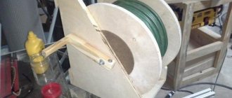
When making a pulse jet engine at home, remember that fixed-diameter pipes can easily be formed using a larger analogue. It is quite possible to carry out the operation by hand using the lever principle, after which the edges of the workpiece are processed with a mallet, bending them to the desired condition. It is desirable that the ends form a plane when joined, which will improve the placement of the weld. It is more difficult to bend sheets into a pipe; you will need a sheet bender or rollers. Not everyone has this professional tool. As an alternative, yews can be used.
An important and painstaking point is welding a thin sheet of metal. This will require special skills, especially if the process involves manual arc welding. It is better for beginners not to try to experiment (the slightest overexposure of the electrode at one point leads to burning a hole). In addition, bubbles can get into the seam area, which subsequently guarantees a leak. It is best to grind the seam to a minimum thickness, which will allow you to see the defect immediately with the naked eye. The conical segments are bent manually and the narrow end of the workpiece is pressed around a small diameter pipe, applying more force than on the wide part.
In the next episodes
Unfortunately, it is impossible to describe all the nuances of the work in one article. It is generally accepted that these works require professional qualifications, but with due diligence, all of them are accessible to the amateur. We, journalists, were interested in mastering new working specialties, and for this we read textbooks, consulted with professionals and made mistakes.
We liked the body we welded. It's nice to look at, it's nice to hold in your hands. So we sincerely advise you to take up such a task. In the next issue of the magazine we will tell you how to make an ignition system and start a valveless pulse jet engine.
A pulsating air-breathing engine (PuARE) is one of the three main types of air-breathing engines (PRE), the peculiarity of which is the pulsating mode of operation. The pulsation creates a characteristic and very loud sound, by which these motors are easily recognized. Unlike other types of power units, the PuVRD has the most simplified design and low weight.
Minuses
There are also many disadvantages, namely:
- high degree of noise during operation;
- excessive fuel consumption;
- presence of fuel residues after use;
- increased vulnerability of the inlet valve;
- speed limit.
Despite all the disadvantages, ramjet engines remain in great demand in their segment. Such a motor is indispensable for one-time starts, especially if it is not practical to mount powerful and expensive versions.