A week ago, I talked about the possibilities of 3D printing and how FDM technology makes our lives easier. The article received, albeit a little, but quite enough positive feedback to continue this topic, which means the series of materials can be considered open :)
I would like to warn you right away that I do not want to turn the articles into a meticulous 3D printer’s guide. There is plenty of this goodness in the vastness of the RuNet. My goal is only to push and suggest options, methods and ideas that will simplify the life of a person who is interested in this industry.
Here we go. After the introductory tour, it's time to act. The topic of today's article is the purchase of components.
Before you give your money
First warning - it won't be easy. Assembling a 3D printer yourself requires perseverance and patience. I will be happy if everything works out for you the first time, but from my own experience I will say that there is no fly in the ointment in 3D printing.
Before purchasing components for building a printer yourself, I would like to immediately note that the most important thing for us is to keep the budget as tight as possible.
And it's not really about saving. Personally, I would really like you to experience the delight that comes after printing the first part on a device that you created with your own hands.
Prusa i3 model . Firstly, this is the most budget-friendly version of the printer. Secondly, it is very popular and finding plastic parts for this model is not a problem.
Finally, upgrading this model is a pleasure. You can do this indefinitely, but the main thing is to see noticeable improvements after investing another hundred or two rubles.
By “mechanics” we mean both static and moving elements of the printer. The quality of the models it can print directly depends on the correct choice of mechanics.
There are literally hundreds of various modifications and options for the same Prusa i3 printer. There are a lot of options for replacing components or their analogues, so you can always change or fix something.
Consumables for SLM and DMLS
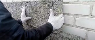
These technologies allow printing on the basis of aluminum, titanium, Inconel, cobalt chromium and other metals and metal alloys. The scope of application of powders of these metals is extremely wide: from medicine to the aerospace industry. Silver, gold, palladium and platinum are printed mainly in the jewelry industry; outside of it, these materials are not in great demand.
ATTENTION : prices for metal powders remain high and can be around $400 dollars per 1 kg. Therefore, today it is profitable to 3D print primarily small metal parts that are too difficult or expensive to create using traditional methods.
It is extremely difficult to work with cobalt-chromium or nickel superalloys using traditional methods. 3D printers create products from such powder with an almost clean surface, which can then be modified using more conventional methods.
Frame
What does it affect ? The body provides rigidity to the entire structure. Please note that while printing the hotend will constantly move up, down, left, right, forward and backward. Sometimes these movements will be very sharp and fast, so the more secure the body is, the better results you will achieve.
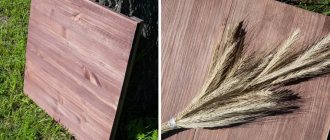
Options . The frame drawing is publicly available (here or here). Then all that remains is to contact offices that cut plywood, chipboard, acrylic or metal.
3-4 millimeter steel will be more expensive, heavier, but more reliable. 6 - 8 mm plywood is cheaper. There are also acrylic options.
Financial advice . Discard ready-made frame options on AliExpress and Ebay immediately. There they ask for three to four times the amount. Look through bulletin boards in your area. The average cost of a plywood body varies between 600 – 1000 rubles. Everything that is more expensive is from the evil one.
Price: 800 rubles (hereinafter – approximate cost).
What printers are there for quick assembly?
With detailed market research on eBay, Amazon and AliExpress, you can find a lot of kits for quickly assembling a printer.
At the moment, the most current models can be considered JGMaker Magic and Tronxy XY-2 Pro.
Both models are pre-assembled by the supplier, undergo debugging, print testing, and then are disassembled into basic units for subsequent transportation and work on site.
Minor differences relate to the actual design and division into components.
I chose the first model (perhaps, the negative experience with the first, not yet completely defeated Tronxy printer had an impact).
Guides (shafts)
What does it affect? Smooth running of the nozzle, evenness of layers.
Options. Exactly six guides are needed for Prusa i3. Two for each axis (X, Y, Z). The dimensions are as follows:
- 2 x 370mm (X axis)
- 2 x 350mm (Y-axis)
- 2 x 320mm (Z axis)
The generally accepted standard for 3D printer shafts is 8 mm. And there is no point in chasing 10 or 12 mm. The weight of the hotend head is not so significant that it would bend the shaft at a distance of 370 mm.
Although, if you have extra money, you can be perverted and buy 12 mm shafts. But the bearings and fitting of plastic parts will be quite expensive later.
Financial advice . Note to perfectionists: rail guides, of course, are a great thing. But their cost, even in China, is downright scary. Leave this upgrade for the future.
By the way, shafts can be bought both on AliExpress (here or here) and locally from the same message boards. The most affordable option is to go to a flea market and find six normal shafts at a disassembly site for printers and old office equipment (MFPs, scanners).
The main thing is to arm yourself with a caliper. All shafts must be strictly the same diameter . The price per piece will be around 60 - 70 rubles.
Price: 420 rubles (flea market option).
Why is 3D printing easy but not popular?
Everything that previously required special skills now comes down to just three. It is enough to be able to:
1. Create 3D models in any CAD package. 2. Assemble and maintain the printer. 3. Manage the process using basic programming knowledge.
That's all the notorious additive technologies in everyday life: you can download a ready-made model for printing, converting it into code is done well by Cura.
The main thing remains: to assemble the printer. And it's not easy.
Some structures, purchased as a kit or assembled with your own hands from individual components, require not only constant attention during operation, but also lengthy assembly with labor-intensive adjustment.
Not the best way to start. As a result, the technology remains the province of geeks, engineers and some fans: board game lovers and owners of rare cars, for whom this method of manufacturing parts or figures allows them to seriously save their budget.
There are very few skilled craftsmen with sufficient motivation, so most turn to those who have already mastered printers due to initial training and a significant amount of time.
Or maybe it could be different, at least for the simplest tasks? Maybe. Even a small child can master 3D printing at home.
Bearings
What does it affect? Noise level, print quality, evenness of layers and edges of the part.
Options. And again it all comes down to budget. You can order a bearing in a block (model SC8UU, for example, here). You can just use a linear bearing LM8UU. You can choose bronze or brass bushings for your car generator. The main thing is to choose the right size.
Finally, you can order bearings from the 3D printer from whom you will buy parts for your printer (more on this below). Ready-made bearings of all sizes are available here.
Remember, for Prusa i3 you need 12 linear bearings .
Financial advice . Don't rush to order bearings in China. It's not a fact that it will be cheaper. Options for 40 - 60 rubles apiece can also be found in the “native lands”.
Issue price: 600 rubles.
Advantages of a homemade 3D printer over a purchased one
Assembling a homemade 3D printer is now available to everyone. For these purposes, you need to have a little engineering education, programmer skills, time spent and a certain amount of money, approximately 25,000 rubles. For many, it’s easier to spend 15-20 thousand on a finished model. But due to the cheap quality of the Chinese assembly, the device will not last long. This reason is quite justified.
The main difference between a purchased 3D printer is that the body is made of acrylic and plywood. This leads to a number of unpleasant consequences:
- the device needs constant color calibration;
- the position is unstable and print quality deteriorates;
- rigid printing of components.
The main advantage of homemade 3D printers over purchased ones is the quality of the frame. Steel material can be used. This will give better fixation to the device and increase its service life.
Using it at home will allow you to independently produce parts that can only be made on machines. For example, create a car body.
Reference! Using a 3D printer you can print a prosthesis. And considering its use at home, it will cost much less than in medical institutions.
Why assemble a 3D printer with your own hands, and what is its advantage over a purchased one, you will learn from this video:
Plastic parts
It's time to turn to those who already have a 3D printer. Look for advertisements for “3D printing in your city.” Discuss the cost of printing a kit of parts for the Prusa i3.
As a rule, they are priced per gram of printing, but there are also ready-made kits. There is no point in pulling this stuff from China.
Price: about 1000 rubles, but depends on the impudence of the printer.
Assemble yourself or buy ready-made?
A story about self-assembly of a printer appeared on the pages of iPhones.ru. Unfortunately, very little attention was paid to setting up and debugging the equipment.
However, even in that case, the printer did not print perfectly straight out of the box, or rather, immediately after assembly. The same thing awaits most ready-made kits purchased in the form of a construction set.
Well, it's the same story every time. My first Tronxy X3 was assembled in a few days, after which it took 2 weeks to fine-tune. And another month for minor repairs, replacement of components and re-debugging.
The impression was spoiled: crooked figures and details over and over again discouraged the desire to work. I had to change the power elements, guides and buy additional sensors.
Do-it-yourself kits are subject to minimal inspection. Therefore, when buying a printer as a set of parts, you may encounter low quality of individual elements or the absence of something.
If you buy and assemble in parts, the result will be a little better - you can check each element. But it will take much longer, and sometimes more expensive.
Belts, pulleys, studs and other small items
There is very little left for self-assembly of the printer mechanics. In fact, these are inexpensive parts, about which there is no point in talking too much. Therefore, I will give a list.
- GT2 belt – used to move the hotend and table along the X and Y axes. It looks like this. 2 meters is enough.
- GT 2 pulleys - internal diameter 5 mm, number of teeth (usually) 20. Placed on stepper motors (two) to move the GT2 belt. Two pieces are enough . They look like this.
- studs - we don’t take fancy trapezoidal screws with a nut. First of all, it's expensive. Secondly, it's pointless. This is not a CNC machine. You won’t be able to jump at speeds higher than your butt, so don’t waste your money. An ordinary construction meter pin with a diameter of 5 mm for the Z axis (cut into two) and the same with a diameter of 8 mm for securing parts of the body.
- bearings - two for connection with the GT2 belt. They will act as tensioners. It is desirable that the outer diameter of the bearing be equal to the outer diameter of the pulley in the area of the teeth. As an option, but you don’t need 50 pieces, just two.
- nuts, bolts, washers - in the hardware store, stock up well on M3 bolts ranging in size from 10 to 60 millimeters. Accordingly, nuts (you also need 8 mm ones for the body studs) and washers. An approximate list can be found here.
- couplings - will hold 5 mm studs along the Z axis. Two of them are needed. You can buy it, for example, here. Or you can ask a 3D printer to print it, taking the model from here.
Financial advice . Don't try to take the best. Approach wisely and check diameters. So, the optimal studs for Z are 5 mm. 8mm ones have a larger thread pitch, which will affect the print quality (there will be too characteristic layering).
There is also no point in chasing pulleys for the belt. A regular bearing will do. Use your imagination when purchasing. The option “stupidly buy from the list” does not work here.
Price issue: if you really want to, you can easily fit in 700 - 800 rubles.
Without electronics, the printer will not work and will not understand what you want from it. Fortunately, the price of components has dropped significantly and you can purchase without a blow to the family budget.
Now actually how it was put together, what difficulties there were and how they were overcome.
To begin with, you need to convert the EM-336 stepper motor from unipolar to bipolar, remove the installed spool (my brother pressed it out for me on a press, but you can also try it with a grinder).
Rework
The conversion from unipolar to bipolar is described in detail and beautifully in the article Converting a stepper motor from unipolar to bipolar on 3d today, it’s a pity the article came out a year after my torment, it’s good there are good people, user wolfs_SG
from the TriDashnik forum thank you very much! I got it like this: it was
became
Housing
To calculate the housing and parts for the necessary components (thickness and length of the shafts, dimensions of the print area, the method of moving the Z axis - on a screw stud or on a belt), go to the Smartcore project page on YouMagine, it describes what components are required and in the Documents section scripts for OpenJSCAD. I used v.1.2 to calculate the body and parts (except for the Z axis, because in this version of the script there is no option for calculating the axis on the stud) and v.1.0.2 to calculate the parts of the Z axis. (Currently on YouMagine that something is broken and the scripts do not open. To open, you can save the scripts to disk, go to openjscad.org and load the script saved on disk). After calculation, the parts are saved in stl in one file, and I had to resave the required parts into different files.
I already calculated the dimensions of the case myself (for the side walls, where the Y-axis fastenings are located, it is better to add a couple of centimeters to the calculated ones), to suit my layout, then I ordered sawing and gluing the edges from 10 mm thick MDF at the market from kitchen dealers. I was very surprised when I picked up the order - the cost turned out to be $5, taking into account the fact that the acrylic frame with fasteners and studs cost me $40. Then he cut the necessary holes and windows himself and assembled them with self-tapping screws. For beauty, I printed white caps and glued them onto the heads of the screws with hot glue. I’ll tell you below where the bunch of round holes came from.
XY axes
After assembling the body, it was time to print the parts. Without rework, I initially printed 7 parts - the carriage, the X-axis guide mounts, the Y-axis distant guide mounts, and the stepper mounts (aka the front Y-axis guide mounts). All parts were printed using filament-free transition PLA with 50 or 60% infill. When assembling the Y axis, a jamb came out - when trying to fix the guide in the right front mount, the seat under it cracked. But with the left part it turned out even worse - when printing, I did not take into account one important fact - in printer steppers only 23 mm of the axle sticks out of the body, and due to the design, the left spool is higher than the right, and it turned out that with the original part the length of the stepper axle was not enough. I immediately started considering options with different crutches, but then it dawned on me - I have a printer, a bunch of plastic and Thinkercad! Both mounts were imported into Thinkercad, the seat for the guide was strengthened in them, and the motor in the left mount was raised 12 mm up. Now after printing and installation everything was in accordance with the intended design.
I still don’t quite understand how the limit switches are attached in the original, and the mounts for them were designed in Thinkercad.
Photos of limit switches
X axis limit switch
Y axis limit switch
Z axis limit switch
Lyrical digression:
In general, Thinkercad is our everything! I tried to design in the compass - it didn’t work, I didn’t get further than registering and installing the client in Fusion 360, OpenSCAD is a good thing if you need to change parameters, but it’s not the same - all this had to be studied. “He has become old, lazy” ©White Sun of the Desert. I wanted something like Windows Paint, only in 3D. And then Thinkercad came to hand! If you understand the primitives, addition and subtraction, you can design simple parts or correct imported ones. The only thing that is really missing is a tool for chamfering - manually is often tedious and lazy. In general, I recommend it to anyone who doesn’t have time or is too lazy (like me).
Let's continue.
Hotend
I didn’t like the hotend mount and its cooling from the original project and I used the mount from this project, but with some changes (I cut off the induction sensor mount and trimmed it a little around the edges to fit into the carriage).
hotend mount
print as in the picture, the left part with supports.
If the left part is turned 90 degrees along the X, the layers where the nuts were inserted are torn apart, despite 100% filling. And so - 3 perimeters and off we go. Cooling the hotend
I used the cooling from this project, I just took the cooling for the left hotend and turned it 90 degrees on mine. As I indicated at the beginning, the hotend is a Chinese E3D V6, 1.75 filament, currently 0.4 nozzle. Thermal barrier passes through a 4 mm Teflon tube all the way to the nozzle. At one time I had a lot of trouble with pryusha, and now these are the only ones I use. To cool the hotend, a 3010 fan is used, it’s enough, they’re just noisy (we need something better, we’ll just have to negotiate with a toad). To cool the part there is a 5015 turbine, but it only blows on one side of the part. There are plans to install radial airflow.
Carriage with hotend
Z axis, table
The fastening of the Z-axis guides and the table fastening are taken from this project, but again with changes, besides, in this project and in the original, the seat for the bearing is shifted in the upper fastening. Also, after assembly, it turned out that the linear bearings were hanging in their seats, which was fixed using FUM tape. The table was made from a piece of stainless steel 15*15 cm, 1.5 mm thick. Calibrating the table is done the old fashioned way, by tightening the screws on the corners of the table and a piece of paper. There is no heating, I print with PLA plastic. The table is covered with ordinary 4 mm window glass, secured with office clips. On the glass is a sticker, trimmed to the required size. I bought it on Ali at the Big Tree Tech store and the impressions are very contradictory - everything was immediately glued normally and removed without effort, but as I used it, it became more and more difficult to remove the printed material (if you look closely you can see two deep scratches from a spatula), and the first layer goes on normally only if you wipe it alcohol.
Z axis and table
The history of the origin of the holes in the walls
After assembly and configuration, I turned on the printer and got scared - when moving along the XY axes, there was a sound as if two pioneers were standing next to each other with drums and beating a drum roll on them. To reduce this effect, I took crowns and drilled holes, but the effect of such an upgrade was minimal. And the project was abandoned. After some time, I read an article on YouTube about replacing and using TMC2208 drivers. The drivers were ordered and installed after a month of waiting. After installation, the effect is amazing - the loudest unit is the same fan 3010. And the cut holes had to be refined, but there is something to hold onto when carrying it
Electronics and firmware
The standard kit for a beginning designer is Arduino Mega 2560 + RAMPS 1.4. Arduino with its quirk - it works fine with the computer on the included half-meter USB cable. On the longer ones it’s all pitchforks. Changing ports, USB 3.0 - purple, doesn't work and that's it. For graphic display and working with a memory card, I initially wanted to do it on OLED, as in this article. I bought everything, assembled it, configured it, turned it on... and it didn’t take off. The image appears for a second and disappears. I couldn’t understand why this was so, and my knowledge of Arduino construction is not enough. To remedy the situation, I ordered an MKS Mini 12864LCD on Banggood for $9 (at that time coupons of 5 from 10 for points still worked, there was time). When purchasing, keep in mind that RAMPS requires an adapter. With this controller everything went more fun - everything took off the first time. The controller had to be placed somehow beautifully - and again I took the model from this project and creatively redesigned it. The drivers are written above - 2 * TMC2208 (X, Y axis), 2 * A4988 (Z axis, extruder).
The drivers were set to a current of 0.7-0.8A. When setting up the TMC2208, there is a serious nuance - the current is adjusted with the motors turned off!
When I changed the A4988 to the TMC2208, I didn’t touch anything in the firmware, I didn’t remove the jumpers in the RAMPS either, I just turned over the stepper connectors (you could not touch anything, then in the firmware it was necessary to change the INVERT_X_DIR, INVERT_Y_DIR parameter, but due to natural laziness, unroll connectors turned out to be faster).
And I almost forgot, it is highly recommended to go to the printer menu and reset the EEPROM settings
. Since I print PLA and there is no table heating, it is powered by a 10A power supply, which is quite enough. To make the sandwich of mega, ramps and drivers less heated, an 8 cm fan from an old power supply is used (according to my suspicions, it is also from an AT power supply unit and is about 30 years old, but quite quiet for its age).
To manage everything, Marlin 1.1.5 is used (at the time of assembly this was the current version). The firmware was taken from marlinfw.org and configured from scratch. Since the quilt and belts were already assembled, the same spools and pins were used, almost all the main parameters were taken from the quill firmware. Since CoreXY kinematics are used, I almost broke my head with these parameters:
#define INVERT_X_DIR true #define INVERT_Y_DIR true #define INVERT_Z_DIR true I took them from the firmware of the original project, looked at others, turned over the connectors of the steppers and even though you didn’t crack the carriage moved along the XY axes as it should - if one axis is normal, then the second one is fine inversions. But in the end I found the required combination and everything worked as it should. If anyone is interested, here is a link to Google Drive with the firmware.
Electronics and firmware
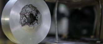
The spool holder remains. This is the essence of two projects - a mount and a reel holder. Since I print on the balcony, and the printer itself is stored in the room, it turned out to be very practical and greatly reduces the storage space.
Reel holder
Stepper motors
This is the most expensive cost item when assembling a 3D printer yourself. You need 5 pieces of Nema 17 . As a rule, I take it at 1.7A current. There will be plenty of their power. The diameter of the shafts is 5 mm. You can take a closer look here.
Yes, don’t forget to check the availability of connecting wires so you don’t have to dance around with a soldering iron later.
Financial advice. And again the flea market and dismantling of MFPs, printers and plotters. Inquire about prices for stepper motors. Sometimes five Nema 17 engines can be purchased for a ridiculous 800 - 900 rubles.
Important: choose engines so that they have the same number of steps per revolution (for example, 200). It’s a bit of a hassle to take engines without markings, because then you’ll be tormented by selecting the right parameters when setting up the software.
Securing the Y-MOTOR axis
Once the base of the frame is built, you can continue to complete the Y-axis pinning. To do this, you will need the following 3D printer parts:
- NEMA 17 HR 0.9 degrees per step 4.0 kg/cm stepper motor.
- Part number: 42BYGHM809.
- 20-tooth pulley GT21 meter gas distribution mechanism GT2.
- Screws 5x M3 x 12 mm.
- Washers - 4x M3.
- Nuts - 2x M3.
Start by attaching the stepper motor to the Y-MOTOR piece on the back of the frame. Also attach the GT2 pulley to the motor shaft. Then you need to adjust it.
Next, connect the Y-BELT-HOLDER to the working platform platform. Use M3 x 12mm screws with washers and nuts. The Y axis will be moved using the GT2 belt. Now attach the GT2 belt and wrap it around the GT2 pulley. Secure the belt to the Y-BELT-HOLDER using cable ties, and adjust the belt tension using the M4 screw on the Y-shaped stop.
Control board
Reference for Prusa i3: Arduino Mega board + Ramps 1.4 expansion module (for example, this option). This is the most affordable and versatile option for printer control.
Advice . Be sure to make sure jumpers (small contact jumpers) are available. Ideally, there should be at least 18 of them. If it doesn’t, you’ll be exhausted later looking for them in your city, even though they cost a ruble per bucket.
I assembled the printer in half an hour. How it was
Assembly and setup of JGMaker Magic is incredibly simple. All measuring operations that accompany conventional Chinese printers are excluded.
The belts are pre-fixed to the required length, the profile is neatly cut and offers the only method of assembly without the possibility of adjustment, the harnesses and terminals are labeled. You just need to collect it.
Assembly takes the following stages:
1. Unpacking and releasing parts from shipping film.
2. Installing the first carriage on the X-axis profile.
3. Mounting the print head on the X axis.
4. Completing the X-axis assembly by installing the second carriage and drive belt.
5. Y-axis motor installation.
6. Installation of the second vertical profile.
7. Connection of the X and Y axes.
8. Installation of studs - lead screws (requires control of the installation angle).
9. Fixing the top bar and completing mechanical work.
10. Connect the wires according to the markings according to the instructions.
11. Integration of plastic rod feeding tube into the print head.
12. Insert the supplied flash card into the printer.
13. We turn it on to the 220V network.
Done, you can print. Depending on your skills, the process takes 15-30 minutes and requires only the tools included with the printer.
Stepper motor drivers
These are miniature scarves that will control stepper motors. We count how much is needed:
- 2 A4988 drivers for the Z axis (like these)
- 1 x A4988 driver for Y axis
- 1 x A4988 driver for X axis
- 1 DRV8825 driver for extruder (for example, these)
You can take it as a lot, or separately. I specifically wrote one driver, DRV8825, because it has a maximum pitch division of 1 in 32, which allows for more accurate plastic extrusion when printing very small parts.
Theoretically, you can take all five A4988 or a set of five DRV8825. It's up to you to decide, but one DRV8825 in the assembly is strictly welcome.
Advice. If you find yourself on sale, don't be lazy to take a couple of drivers in reserve. During the initial assembly there is a risk that you will burn one of the drivers :)
Main characteristics of SLM & DMLS
In SLM devices, a laser melts each layer of metal powder individually. Temperatures change dramatically, causing internal stresses to appear in parts. This may negatively affect the quality of the product, although in any case it will be higher than with casting. Products printed on SLM printers are superior to DLMS analogues in terms of safety margin and solidity.
When working using DLMS technology, internal stresses are not created, so the quality of products is disproportionately higher than that of analogues made by stamping or casting. This is especially in demand for the aerospace and automotive industries, as the components used in them must be extremely durable.
Hotend and plastic feed mechanism
This block is where the magic of 3D printing happens. Here a plastic rod is heated and squeezed through a miniature nozzle. I won't beat around the bush. An option that has been proven over the years is the V6 hotend version with a cooler, a 100k thermistor, a heating element, a radiator, and a Teflon tube. For example, this one.
It is better to take a metal one for the plastic feed mechanism (which will be mounted on one of the NEMA 17 motors). Firstly, it is more convenient to assemble, and secondly, skipping steps during printing is completely eliminated.
SLM or DMLS: what's the difference?
Both of these technologies are now actively used for 3D metal printing. SLM involves selective laser melting of metal powder, while DMLS involves direct laser sintering of metal. In both cases, a laser is used to selectively melt grains of metal powder, bind these grains together and create products layer by layer.
The difference between the technologies is as follows:
- In SLM, metal powder is melted.
- DLMS does not use such high temperatures, so the metal does not liquefy. The powder particles simply sinter together.
Both technologies are protected by patents.
Table, springs, glass, end switches
The platform on which the 3D model will be located must have mandatory heating. Temperatures here reach 100 – 110 degrees Celsius, depending on the type of plastic.
The most affordable and time-tested option is MK2 measuring 214 x 214 mm. Don't forget to purchase springs for the table (you need 4 pieces). They make it much easier to set the nozzle level.
The top of the table is covered with ordinary glass 3-4 mm thick. Ideally, a mirror. Dimensions 200 x 200 mm with slight bevels on the edges for fastening screws. The asking price for a glazier is about 60 rubles; there is no point in bringing it from China.
Limit switches are special mechanical buttons that will limit the size of the table and “explain” to the electronics where the end of the printer’s working area is. As an option, inexpensive KW12-3. You need 3 pieces (one for each axis).
Inexpensive and quick start in 3D printing
For a quick start, some kit developers offer fully assembled 3D printers or kits made up of several basic large units: most often this is a printing unit, combined X and Y axes, an assembled printing table and a control unit.
Benefits:
1. The kit is pre-assembled and tested.
2. Load-bearing and power elements undergo separate quality control.
3. Assembly takes much less time.
In addition, usually such microconstructors with 10-15 elements are intended for schoolchildren, therefore they come with simplified firmware, a full set of software and additional functions that simplify work.
power unit
One of the key elements of all electronics is the power supply. The finished version, designed for 3D printers, will cost 800 – 1200 rubles. It all depends on the power of the block. I’ll say right away that 15 A and 12 Volts will be enough for a 3D printer with two extruders and one heating table.
Financial advice . Alternatively, you can use a computer power supply of similar power. A used option will cost 200 - 300 rubles, but will work just as well. The only thing is that you will have to tinker a little with decoupling the wires.
Preparation for use
After assembly and installation, the user has a few more steps that must be completed to fully launch the homemade device:
- Software installation. In this case, you will need to download a program for the Arduino control board. It is better to download utilities from the official website of the developer.
- Firmware installation. Connect the Arduino using a USB cable and download the official drivers. Unzip the file, then open the Marlin application, through which you need to install the firmware: open the tab in the top menu “Tools” -> select the Arduino board -> specify the appropriate port. Next, open the Configuration tab, click the “Download” button.
- Installing a program (slicer) on a PC to configure and prepare printing. Any compatible application can be used. For example, Cura. Set up the program for the printer. Most likely, this point will take a long time, since the user will do a bunch of tests before finding the optimal combination of parameters.
- Platform calibration. This is usually done using a blank sheet of A4 paper. It is placed between the heating table and the extruder nozzle. Then adjust the gaps using adjusting screws.
- Installing the filament and loading the filament into the extruder. It is worth buying several rolls of material in advance to understand which one will work best in the printer.
- Loading the model into the slicer. Preset print settings. Usually the printer is checked using a cube model. This is the simplest test that shows childhood sores of the device.
- Transfer the configured model to the SD card. Printing the finished file on a printer.
This is a general scheme for preparing a printing device for operation.
Ninth: attention to the extruder
The drive that feeds the plastic fiber will consist of a NEMA 17 stepper motor and a MK7/MK8 gear drive. You will also need to download the driver for controlling the printer extruder elements - this can be done using the following links:
- Extruder idle: e-waste_extruder_idle
- Extruder “body”: e-waste_extruder_body
- "Hot nozzle": RepRapPro_mount
The operating principle of the extruder is as follows. The plastic fiber will be drawn into it and fed into the heating chamber. Between it and the fiber drum, the fiber is directed inside a heat-resistant Teflon tube. The direct drive is assembled by attaching a stepper motor to it and mounting it on an acrylic frame. To calibrate the flow of plastic, we measure the distance and lay the tape in this area. Now we go to the Repetier software, where we set the resulting figure on the extruder.
Printing table
We drill four holes with a diameter of 3 mm in a wooden slab 20x13 cm.
After this, tighten 4 M3x25 bolts.
What to prefer and where to start?
JG Maker Magic is suitable for printing most popular materials available in stock, excluding wood and polycomponent materials.
It is also possible to upgrade the device with an automatic level sensor to calibrate the print head relative to the table. It would be a good idea to install a second axis to move the table.
However, all this may not be needed soon: the printer is ready to work even with factory settings, changing them after the basic concepts of the process have been mastered in practice.
When purchased in May, it cost me 14,000 rubles. The cost varies depending on the exchange rate and the proximity of the sale, but if you wish, you can buy it now for about this amount of money.
Among the alternatives, it is worth noting the already mentioned Tronxy XY-2 Pro with a color control screen, a larger print area and the presence of an inductive calibration sensor.
In return, you will have to sacrifice accuracy (0.05 mm for Magic versus 0.1 mm for Tronxy). Tronxy takes longer to assemble because the entire frame is disassembled. In theory, this could lead to printing problems. Past experience with a similar device speaks for itself.
Subjectively, the basic Magic firmware is more interesting, as is the printing stability.
However, to get started in 3D printing, any quickly assembled printer with a metal frame and more or less standard “brains” is suitable.
It is advisable if it has a movable table with automatic heating, a filament change sensor and a limit switch for determining the level.
So the cost of entry into a new profession turns out to be much lower than it might seem. Meanwhile, it is the future: the design of CNC machines and professional devices for 3D printing differs only slightly.
PS Are there any of our readers who use 3D printing at work or as a hobby?
(
17 votes, overall rating: 4.41 out of 5)