Radio designer automatic lighting effects
FM receiver with LCD display. Assembly kit. DIY KIT
Hi all! The summer season has arrived, summer is ahead, and this means that you need to purchase an FM receiver
. But, as you know, the best radio receiver is a receiver made by yourself. PR
I received this set for free from the Chinese online store BangGood, but despite this, I declare with full confidence that I do not bear any obligations to the store, so the review will be honest and unbiased. Let's go! =)
So, today we are reviewing a kit for self-assembly of an FM receiver with an LCD display.
I'll start, as always, with the packaging. A standard postal package containing a large amount of foam rubber, so you don’t have to worry about the safety of the ordered set. Although…=))
No, this time everything arrived intact. The set consists of a body, in my case it is black, but you can also buy it in white. Two boards: a small one for installing the display and buttons, a large one for installing all other parts. By the way, they sell two versions of these construction sets - more complex and simpler. In a simpler set, the small board is already equipped with a display and the necessary elements; in a more complex version, you need to install all this yourself. In my case, the option is more complicated.
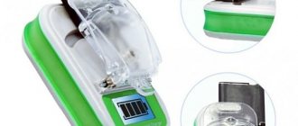
To install the display we need a metal press and a conductive sticker, all of this is included in the kit.
But before mounting the display on the board, it is better to first solder the display driver (a small board with a chip) and install a quartz resonator, three capacitors and a diode.
Now let's move on to mounting the display. There is double-sided tape on the board, onto which we fix the LCD screen. Then degrease the surface of the board and display using alcohol and a cotton swab. Remove the protective layer from the striped sticker and glue this sticker onto the glass of the screen. Next, we warm up the press, for example, using an iron; I heated it with a hairdryer from a soldering station. And while the press is still warm, apply it to the sticker.
Half the job is done. Now we glue the remaining part of the sticker onto the contacts located on the board and also press this area with a hot press. That's it, the screen is installed. =)
By the way, I made a mistake and decided to first heat not the press, but the sticker itself, but it curled up due to the flow of hot air, so I had to glue a new one. There are six of them in the set. After this you can move on to the big board. Here I started by installing resistors. Using a multimeter, I determined their values and, in accordance with the diagram, placed them on the board.
I then decided to install ceramic and electrolytic capacitors and two transistors. Do not forget to observe the polarity of electrolytic capacitors. Also note that the three capacitors are located horizontally relative to the board, otherwise they will not fit into the case.
And finally, we install a variable resistor and capacitor, two microcircuits, a button and a headphone jack. Be sure to ensure the correct placement of the chips. There is a key in the form of a circle on the board and on the microcircuits themselves.
Next, you can solder the wires to the contacts of the battery compartment. We solder the remaining ends of these wires onto the board.
Similarly, we connect the speaker and the radio receiver board.
Now we prepare the antenna. We take the gray wire from the set. We solder one end to the adapter. We insert the antenna into the housing and attach an adapter with a soldered wire to it, and secure the whole thing with a screw.
At this stage of assembly, you can connect the two boards using five different colored wires.
Next, we install the contact pads of the buttons on the board with the display. We do not solder them under any circumstances. You can use hot melt adhesive for fixation. That's what I did =)
Now you can install the buttons themselves into the radio body, but before that we cut off one (as in the photo). Since the sixth button is soldered to the main board.
We put the board with the display on top, not forgetting to remove the protective film =) And fix it with two screws. Two more screws are screwed in at the very end of the assembly, through the battery compartment.
We install the speaker into the housing, which we fix with hot glue (you can also use regular super glue). We put a “twist” on the adjustable capacitor and tighten it with a screw.
Now you can install the main board; the screws from the kit are used for fastening. Well, finally we solder the wire from the antenna to the board. Congratulations, the build process is almost complete! But don't rush to completely assemble the body. First, insert the batteries and check the frequency range that appears on the screen. We need to achieve readings from 74.0 to 108.0Mhz. In my case, the maximum frequency was within 83.0Mhz. If you also have problems, then turn the receiver with the board facing you. There are 4 regulators visible. We are only interested in the two right ones - upper and lower. When I turned the top one, I noticed how the sound quality changed, but when I scrolled the bottom control, the frequency range changed. I turned it all the way to the right and achieved those same 74.0-108.0Mhz. I can’t say anything about the two left controls. I twisted it, but didn’t notice any changes. Now feel free to assemble the case =) And I will try to explain what the buttons do and how to set the time and alarm clock. The top left button (Power On/Off) turns the radio on and off. When the radio is turned off, the clock appears on the display. Top right button (AL On/Off) - turns the alarm on and off. If the alarm is turned on, an icon will appear on the screen. To set the time, you need to hold down the third button (TimeSet) and by pressing the first button (MinSet) you can set the minutes, by pressing the second button (HeSet) you can set the hours.
If you press the fourth button (AlDisp), the screen will display the time for which the alarm is set. To set the alarm, hold down the fourth button, and then proceed in the same way as setting the clock. =) By the way, the alarm clock does not have its own signals, so the radio station that was last tuned will wake you up.
In conclusion, I want to say that I really liked the set; I haven’t seen anything like it for a long time. It’s made with high quality, it’s quite easy to assemble, but it doesn’t lose interest.
I highly recommend purchasing! Goodness =)
If you liked the review, don't forget to watch the video version!
And I say goodbye to you, I wish you good luck. And bye. =)
The product was provided for writing a review by the store. The review was published in accordance with clause 18 of the Site Rules.
Radio designer television antenna amplifier UHF
Frequency generator set
Next is a kit for more experienced radio amateurs to assemble a frequency generator. It costs $33. In assembled working condition it looks like this.
Frequency generator set
It will not only be interesting to assemble. It will still be a quite useful device in our business. Capable of generating frequencies from 0 to 200 kHz. The output is sinusoidal signals, rectangular, sawtooth, arbitrary shape, which you specify. This device is powered by a voltage of 15 V, and the output voltage range is from 0 to 10 V. In general, it is a useful thing. And putting it together without much difficulty.
Radio constructor television antenna amplifier MV
Adjustable power supply
Next on the plan is the “Assemble it yourself” set - “Adjustable power supply”. The set is large and costs $10. Here's a link to it.
You can assemble the power supply in the case. Indication of output voltage using seven-segment indicators. Moreover, the voltage is from 1.2 V to 37.5 V. There are electrical circuit and wiring diagrams. Everything you need for assembly is included. It is powered from an outlet. And the plug with wire is included in the package.
Radio set LED signal level indicator
Sound module
Sound recording and playback module for just a couple of bucks. It is easy to assemble. What you can do with it is record a sound lasting 10 seconds and play it back using a speaker.
Sound card set
Such a device is suitable, for example, for an audio postcard with a recording of congratulations or music. Or come up with something for jokes and various practical jokes. The circuit works like this: press and hold the record button. The red LED will light up and you will be recording audio for 10 seconds. After recording, click the play button and the recording will play. Subscribe to the channel "Radio Amateur TV".
Radio constructor actuator with photocell
Keith: design a soldering station
Kit - make a soldering station. They cost 19.5 dollars. Power 70 W. The soldering iron temperature adjustment range is from 200 to 480 degrees. The input voltage of the station is 12-24 volts. The instructions describe in detail how to assemble and use this station. Reviews praise this device; the soldering quality is decent.
DIY electronics in a Chinese store.