// connect the library const int pin = 10; // declare the OneWire pin number iButton(pin); // declare the OneWire object on the 10th pin // key number that we want to write in the iButton: byte key_to_write = { 0x01, 0xF6, 0x75, 0xD7, 0x0F, 0x00, 0x00, 0x9A }; void setup(void) {
Serial.begin(9600);
pinMode(pin, OUTPUT); } void loop(void) {
delay(1000);
// delay for 1 second iButton.reset(); // device reset 1-wire delay(50); iButton.write(0x33); // send the “read” command byte data; // array for storing key data iButton.read_bytes(data, 8); // read the attached key data, 8x8=64 bits if (OneWire::crc8(data, 7) != data) { // check the checksum of the attached key Serial.println("CRC error!"); // if the CRC is incorrect, report it return; // and interrupt the program } if (data & data & data & data & data & data & data & data == 0xFF) { return; // if the key is not attached to the reader, interrupt the program and wait until it is attached } Serial.print("Start programming..."); // start the process of writing data to the key for (int i = 0; i } // Initialize writing data to the tablet key iButton: void send_programming_impulse() {
digitalWrite(pin, HIGH); delay(60); digitalWrite(pin, LOW ); delay(5); digitalWrite(pin, HIGH); delay(50);
}
Don’t forget to set the number of your original key in the key_to_write
which we learned earlier.
Let's upload this sketch to Arduino. Open the serial port monitor (Ctrl+Shift+M). Let's connect a key to the circuit, which will be a clone of the original key. The serial port monitor will display a corresponding message about the result of programming.
If this sketch did not work, try replacing the code after Serial.print("Start programming...")
and until the end of the
loop()
to the following:
Additional sketch of writing an iButton key using Arduino
(expands) delay (200);
iButton.skip(); iButton.reset(); iButton.write(0x33); // reading the current key number Serial.print("ID before write:"); for (byte i=0; iHere the writeByte()
will be as follows:
int writeByte(byte data) {
int data_bit; for(data_bit=0; data_bit> 1; } return 0; }
It is pointless to show a time diagram of the operation of the key identifier recording sketch, because It's long and won't fit in the picture. However, I attach the *.logicdata file for the logic analyzer program at the end of the article.
Intercom keys come in different types. This code is not suitable for all keys, but only for RW1990 or RW1990.2. Programming keys of other types may lead to key failure!
If desired, you can rewrite the program for a different type of key. To do this, use the technical description of your key type (datasheet) and change the sketch in accordance with the description. Download datasheet for iButton keys
can be found in the appendix to the article.
By the way, some modern intercoms read not only the key identifier, but also other information recorded on the original key. Therefore, it will not be possible to make a clone by copying only the number. You need to completely copy the key data.
Purpose of the intercom key duplicator
Using the Arduino microcontroller, you can copy the intercom key if you accidentally lost it.
RFID – radio frequency identification.
The device performs the same function as the barcode or magnetic stripe on the back of a credit card. It provides a unique identifier for this object. And just like a barcode or magnetic stripe, RFID must be scanned to obtain information. RFID is used in this project to read data from RFID tags and send the information to the non-volatile memory of the MCU.
The ID read from the tags is compared with the stored information, and if it matches, the door opens.
The principle of operation of a duplicator on Arduino
Each key has an internal connection with the intercom door - this number serves as a key identifier. This intercom key number decides whether you have supplied the correct key. Therefore, the principle of operation of the intercom key duplicator on Arduino is quite simple: first you need to check the “allowed” key, and then assign the same number to another key clone.
By checking the number from its database of allowed data rates, it will open the door. The intercom keys that we will connect to the Arduino duplicator (sometimes called an iButton or Touch Memory) are read and written to the 1-wire interface. Therefore, the connection diagram is very simple.
Electrical Diagram
This is what the copier circuit looks like: a pocket for copying contact keys is connected to the Arduino nano, and the input and output of the rfid module is connected to legs 11 and 7. RGB LED for indicating read/write mode/BlueMode, buzzer for beeping. Encoder - to control the dializer. An OLED display is connected to the i2c bus.
Duplicator circuit
Adult duplicator board diagram from the EasyEda online editor
Gerber_PCB3_20200103004523
Making a duplicator with your own hands
The LCD has 16 pins, which is too many for the Arduino Nano intercom, so it is important to have an I2C adapter. This allows the display to be controlled from just two signal pins on the Arduino. This is useful due to the small number of pins that will need to be controlled from the MCU.
LCD contacts
LCD displays have a parallel interface, which means that the MCU must control multiple interface pins simultaneously to control the display. The table below provides a description of each contact in English:
Contact specification
First, let's make connections between the LCD and I2C. This requires an I2C LCD display adapter (LCD1602). The adapter converts a 16 x 2 LCD into a serial I2C LCD that can be controlled via Arduino with just 2 wires.
Connections between Arduino and LCD
Hardware
To type the code you will need the LiquidCrystal_I2C.h library in the Arduino IDE. The library allows you to connect an LCD display to Arduino. The built-in LiquidCrystal_I2C library makes it easy to display characters on the LCD.
You can download LiquidCrystal_I2C.h from our website here, or from Github - https://github.com/todeilatiberia/SmartDoor.
Follow the instructions below to install the new library in your Arduino development environment.
- First download files from Github
. - Extract each folder from the archives.
- Copy the ZIP files to the Arduino folder.
- Open Arduino and add Keypad.zip: Sketch Menu -> Enable Library -> Add ZIP Library
- Add Keyboard Library: Sketch -> Enable Library -> Keyboard
OSBoy notes.
On the Internet you can find enough ready-made Arduino-projects of devices for copying DS1990 intercom keys, popularly also known as ibutton, or simply “tablets”. But almost all the projects that I found turned out to be somewhat crude. Therefore, it was decided, using existing developments, to make our own project, completely finished and quite functional. This article was taken as a basis, and also some ideas were gleaned from here, so I don’t make much claim to authorship.
Hardware
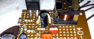
I assembled this device on an Arduino Nano (its Chinese equivalent) in a housing from a non-working USB hub. It turned out quite compact and convenient:
intercom key duplicator - installation
intercom key duplicator assembly
The USB cable is used both to power the device and to interact with the COM terminal. The case has a non-locking button for switching read/write/restore modes, an LED to indicate the current mode, and a contact pad (reader) for keys.
The device diagram is the simplest. The 1wire (ibutton) data line must be connected to the power supply (+5V) through a 2.2 kOhm resistor (most likely, it will work normally with other ratings of the order of 1...4.7 kOhm). We connect the LED through a limiting resistor of a suitable value. Since in the sketch we use the button input (D2) with a built-in pull-up resistor, we set the button to GND.
Intercom key duplicator - diagram
Software part
In the firmware, only the part of the code that is directly responsible for reading/writing data to the keys via the 1-wire protocol and, in fact, the operating principle of the device (so as not to reinvent the wheel) was left virtually unchanged. However, the rest of the software was actually completely rewritten and at the same time supplemented with various useful features. The sketch uses the standard Arduino “OneWire” library. For the current version of the sketch, see the end of the article.
Device capabilities:
- Reading the key ID and then writing to a rewritable “blank” (RW1990);
- Recording a “universal” ID pre-specified in the sketch (in this case, ID is used: 01:FF:FF:FF:FF:FF:FF:2F);
- Protection against accidental recording of an incorrect ID value;
- Recovering unreadable keys accidentally corrupted during an unsuccessful write;
- Entering ID manually in the terminal;
- Possibility of operation without a COM terminal (if there is a 5V DC power supply with a USB connector).
Working with the device
The device can be used either with a COM terminal (preferred) or without it. To work with the terminal, drivers for the Arduino board (FTDI, CH341 or others, depending on which chip is installed on your board) must be installed on your computer. If the board is successfully programmed in the Arduino-IDE development environment, then the required driver is already installed in the system. You can use any COM port terminal you like (for example, Arduino-IDE port monitor or Hyperterminal. Personally, I use PuTTY). In the terminal settings, you need to select the virtual COM port under which our board was identified, and the exchange rate set in the sketch (in my case - 115200).
So, we connect the device to the computer and launch the COM port terminal (the Arduino automatically reboots). The LED flashes several times during the boot process. After a couple of seconds, the device is ready for operation, the LED goes out, and the terminal displays a message indicating that the system is ready.
List of available commands via terminal:
- d — loading a “universal” key into the buffer (in this case: 01:FF:FF:FF:FF:FF:FF:2F);
- w — read/write mode switching;
- m — switch to manual ID entry mode;
- r — switch to recovery mode for unreadable keys;
- h — show help on commands.
To read the key ID , apply the key to the contact pad. At the same time, the LED begins to blink frequently, and the terminal displays the read ID, which is stored in a buffer (oldID variable) until another ID is loaded into it. The ID consists of eight bits, which are displayed in hexadecimal: 01 XX XX XX XX XX XX YY. Here the first bit is the Family code; for ibutton keys it will always be equal to 1. If the read Family code differs from 1, a corresponding warning will be displayed in the terminal and the device will refuse to record this ID. The next six bits are, in fact, the unique key identifier. And the eighth bit is the so-called “redundant code” CRC or, in other words, a checksum calculated using a special algorithm from the previous seven bits. The checksum is checked, and if its value is incorrect, then, again, a warning about this is displayed in the terminal and writing such an ID will be impossible.
To write an ID to a rewritable key , you need to send the “w” character in the terminal, or press a button on the device. At the same time, the LED lights up, indicating that the device is ready for recording. We apply the key to be written to the contact pad: the LED goes out, and after about a second it begins to blink rapidly, which indicates the completion of the writing process and switching the device back to reading mode. If in the terminal we see that the ID we just wrote down is being read, without any warnings, then everything was successful. With the same success, you can copy keys without using a terminal, watching only the LED.
If the ID being recorded was incorrect (with an incorrect Family code, or CRC), a corresponding message will be displayed in the terminal and the recording will be cancelled. Thus, the device protects the key from writing incorrect data to it. However, it may still happen that the data is recorded with errors. This can happen, for example, if the key is not pressed tightly enough to the pad when recording data. Moreover, the key in this case may become completely unreadable by some devices (including this duplicator) if a zero value is written to the first bit. And when experimenting with keys, this often happens, especially due to inexperience! So, without knowing, you might think that the key has died.
To recover an unreadable key, you must switch the device to the appropriate mode. To do this, you need to send the symbol “r” in the terminal, or turn on the device while holding the button pressed. The LED will start blinking rapidly, regardless of whether the key is attached or not (to exit recovery mode, send the “r” character again, or reconnect the device). We apply the key to the contact pad. If it is readable, then its ID is calculated in the same way as in normal reading mode. If the key is not readable, nothing will happen. Keeping the key attached, press the button. In this case, the “universal” ID written in the sketch (for me: 01:FF:FF:FF:FF:FF:FF:2F) or another one previously loaded into the buffer will be forced into the key. At the end of recording, the device will return to normal reading mode.
load a universal ID into the buffer by sending the “d” character in the terminal, or simply by rebooting the device (it is used by default if no other ID has been entered).
Among other things, the device provides the ability to make a duplicate key, even without having the original at hand! You just need to know its ID.
We switch the device to manual ID entry mode. To do this, you need to send the character “m” in the terminal. After this, a prompt appears to enter the ID, or exit manual mode (by pressing Esc). After this, you can enter any ID (in hexadecimal). In this case, the first bit (Family code) must always be equal to 1 and the program substitutes it automatically, and also automatically calculates the CRC and substitutes it into the eighth bit. Thus, we do not need to enter the Family code and calculate the CRC checksum; it is enough to enter only the values of bits from the second to the seventh.
As a result, we have a completely functional, useful device for a ridiculous amount of money. Now you can quickly copy the key to a standby blank anywhere, provided you have a 5V DC power source with a USB connector!
[ Show/hide sketch from 05/25/2017 ] #include const int switchPin = 2; // We will use the hardware interrupt INT0, so the button must be connected to the 2nd pin const int dataPin = 12; // Data pin of the key reader const int ledPin = 13; // Control LED pin volatile boolean writeMode = false; // Recording mode: 1 - enabled; 0 — disabled (read mode) boolean recoveryMode = false; // Recovery mode for unreadable keys (with the first zero byte written by mistake) byte oldID[8]; // Read key ID byte newID[8]; // Key ID to be written const byte defaultID[8] = { 0x01, 0xFF, 0xFF, 0xFF, 0xFF, 0xFF, 0xFF, 0x2F }; // By default, “Universal” ID is flashed: 01:FF:FF:FF:FF:FF:FF:2F byte crc; // CRC checksum OneWire ibutton (dataPin); void setup() { Serial.begin(115200); loadDefaultID(); pinMode(ledPin, OUTPUT); pinMode(switchPin, INPUT_PULLUP); // When you turn on the device, holding the button pressed, recovery mode is activated if (digitalRead(switchPin) == LOW) recoveryMode = true; attachInterrupt(0, int0, LOW); // when the button is pressed, the 0th interrupt is triggered, the interrupt handler (ISR) is the int0() function Serial.println("Device is ready. Send 'h' for help."); } // Loading the default “universal” ID void loadDefaultID() { for (byte x = 0; x < 8; x++) oldID[x] = defaultID[x]; } // Switching mode: Read/Write void changeMode () { // Reinsurance against writing an incorrect ID if (!writeMode) { crc = ibutton.crc8(newID, 7); // Calculate the checksum of the written ID if (newID[0] != 1 || newID[7] != crc) { Serial.println(F("ID is incorrect! Writing is not permitted."); writeModeOff(); return; } } writeMode = !writeMode; digitalWrite(ledPin, writeMode); if (writeMode) { Serial.print(F("Waiting for the key to WRITE the new ID: ")); for (byte x = 0; x < 8; x++) { Serial.print(newID[x], HEX); Serial.print(' '); } Serial.println(" ..."); } else { writeModeOff(); } } // Automatically disable recovery mode after writing and display an invitation to read a new key void writeModeOff() { if (recoveryMode) { recoveryMode = false; Serial.println(F("Recovery mode disabled.")); } Serial.println(F("Waiting for the key to READ the ID...")); } // Button press interrupt handler: switches mode: Read/Write (filtering out contact bounce) void int0() { static unsigned long millis_prev; if ( millis() - millis_prev > 100 ) changeMode(); millis_prev = millis(); } // Output the read ID to the terminal void printID() { for (byte x = 0; x < 8; x++) { Serial.print(oldID[x], HEX); Serial.print(" "); } crc = ibutton.crc8(oldID, 7); // Calculate the checksum of the read ID Serial.print(" CRC: "); Serial.print(crc, HEX); if (oldID[0] != 0x01) Serial.print(F(" Family code is not valid!")); if (crc != oldID[7]) Serial.print(F(" CRC is not valid!")); Serial.println(); } void loop() { // Processing commands sent through the COM port terminal if (Serial.available() > 0) { byte com; // Command sent through the COM port terminal com = Serial.read(); switch ( com ) { case 'h': { Serial.println(F("Help:")); Serial.println(F("d - load default ID")); Serial.println(F("w - switch read/write mode")); Serial.println(F("m - enter ID manually")); Serial.println(F("r — enable recovery mode (send 'r' again to disable)")); Serial.println(F("h - show this help")); break; } case 'd': { if (writeMode) { writeMode = false; digitalWrite(ledPin, LOW); } loadDefaultID(); Serial.println(F("Default ID is loaded.")); printID(); break; } case 'w': { changeMode(); break; } case 'r': { writeMode = false; recoveryMode = !recoveryMode; Serial.println(recoveryMode ? F("Recovery mode enabled.") : F("Recovery mode disabled.")); break; } case 'm': { byte inputID[8]; // Manually entered key ID char inputChar; // Code of the entered character char inputNum = 2; // Serial number of the entered symbol (from 0 to 15). We start entering from the 2nd character, because... 0th and 1st are fixed. char charEncode; // Hexadecimal number (from 0 to F) to which each ASCII character entered is converted boolean even = 0; // Sign of parity of the serial number of the entered character Serial.println(F("Enter the new ID, or press 'Esc' to cancel.")); inputID[0] = 1; Serial.print(F("The new ID is: 01 ")); while (inputNum < 14) { if (Serial.available() > 0) { inputChar = Serial.read(); if (inputChar == 27) { Serial.flush(); Serial.println(); Serial.print(F("Canceled...")); break; } else { if ( inputChar >= 48 && inputChar <= 57 ) charEncode = inputChar - 48; else if ( inputChar >= 65 && inputChar <= 70 ) charEncode = inputChar - 55; else if ( inputChar >= 97 && inputChar <= 102 ) charEncode = inputChar - 87; else inputNum = -1; if ( inputNum != -1 ) { Serial.write(inputChar); if (!even) inputID[inputNum/2] = charEncode << 4; else { inputID[inputNum/2] = inputID[inputNum/2] + charEncode; Serial.print(' '); } even = !even; inputNum++; } } } } if (inputNum == 14) { inputID[7] = ibutton.crc8(inputID, 7); // Automatic calculation of the checksum of the entered ID for (byte i=0; i<8; i++) oldID = inputID ; } Serial.println(oldID[7], HEX); printID(); break; } } } for (byte x = 0; x < 8; x++) newID[x] = oldID[x]; // Check if the key is attached if (!ibutton.search (oldID)) { ibutton.reset_search(); delay(50); if (!recoveryMode) return; } // Read mode if (!writeMode) { digitalWrite(ledPin, HIGH); delay(50); printID(); digitalWrite(ledPin, LOW); } // Write mode if (writeMode) { delay(200); digitalWrite(ledPin, LOW); ibuttonCommand(0x33, 1, 1); Serial.print("Old ID: "); for (byte x = 0; x < 8; x++) { Serial.print(ibutton.read(), HEX); Serial.print(' '); } ibuttonCommand(0xD1, 1, 1); // set the line to logical 0 digitalWrite(dataPin, LOW); pinMode(dataPin, OUTPUT); delayMicroseconds(60); pinMode(dataPin, INPUT); digitalWrite(dataPin, HIGH); delay(10); Serial.print(" New ID: "); for (byte x = 0; x < 8; x++) { Serial.print(newID[x], HEX); Serial.print(' '); } ibuttonCommand(0xD5, 1, 1); Serial.print("Writing..."); for (byte x = 0; x < 8; x++) { writeByte(newID[x]); Serial.print('*'); } Serial.println(F("OK!")); ibuttonCommand(0xD1, 0, 1); // set the line to logical 1 digitalWrite(dataPin, LOW); pinMode(dataPin, OUTPUT); delayMicroseconds(10); pinMode(dataPin, INPUT); digitalWrite(dataPin, HIGH); delay(10); changeMode(); } } // Sending an iButton command void ibuttonCommand(uint8_t command, boolean sk, boolean rs) { if (sk) ibutton.skip(); if (rs) ibutton.reset(); ibutton.write(command); } // Write a new ID byte byte void writeByte(byte data) { for (int data_bit = 0; data_bit < 8; data_bit++) { digitalWrite(dataPin, LOW); pinMode(dataPin, OUTPUT); if (data & 1) delayMicroseconds(60); pinMode(dataPin, INPUT); digitalWrite(dataPin, HIGH); delay(10); data = data >> 1; } }
It is possible that the device’s firmware will continue to be improved. If you notice any bugs or shortcomings in the program, constructive criticism is always welcome!
Software part
We will connect a keyboard to display the numbers on the LCD for Arduino and copy the key we enter from the keyboard.
Keypad.h is a library that allows the Arduino to read a matrix type keyboard.
This project uses a 4×4 keyboard.
The table shows the connection between the Arduino board and the keyboard. The keyboard pins are connected to the digital output pins of the Arduino. Pin D6 was used for the buzzer because it was a PWM pin.
| Keyboard output | Arduino pin |
| 1 | D2 |
| 2 | D3 |
| 3 | D4 |
| 4 | D5 |
| 5 | A0 |
| 6 | D7 |
| 7 | D8 |
Connection between Arduino, LCD and keyboard
LCD and keyboard connected to Arduino
Then let's add RFID. In this case, the RFID board uses the SPI communication protocol, where the Arduino will act as the master and the RFID reader as the slave. The card reader and tags are designed to communicate at a frequency of 13.56 MHz.
This is an important step as it helps us read the data from the card and it will decide if the ID matches the information stored in the EEPROM. If it matches, it will give us access and display "Unlocked". Otherwise, the LCD will display “Locked”.
Connection between Arduino, LCD and RFID
Intercom on Arduino, LCD and RFID
The next step is to add a buzzer and 2 LEDs to simulate a controlled access system. Check out the chart below. The buzzer is set so that it buzzes whenever we gain access (unlocked). The red LED is always on when it is locked, but the green LED is on when it is unlocked.
To protect the modules, you need to use 3D printing of the housing. If you don't have a 3D printer, you can simply use a plastic housing that allows you to slot all the components inside. This is very useful because the modules will be placed inside and the only parts outside the box will be the LEDs, keyboard and LCD.
Wiring diagram showing the connection between Nano, LCD, Keypad, RFID and Beep
The code for downloading to the microprocessor is available at the link:
www.deviceplus.com/how-tos/arduino-guide/make-your-own-arduino-rfid-door-lock/
Intercom key programming
It is quite difficult to intentionally damage the intercom key, but it is possible. So what could happen? A magnetic key for the intercom (duplicate) will be needed if contactless cards or bracelets are broken due to kinks or kinks. It is impossible to demagnetize such keys when they are near a phone or plastic cards.
The “tablets” can be damaged by exposure to strong voltage, for example, by placing them in the microwave. They are quite durable and rarely fail. However, if you have several keys for different entrances, they can be combined using the so-called universal intercom key.
Three ways to make a copy of the key:
- The production of intercom copies is carried out by a specialized organization or by a master who will do it in a few minutes upon presentation of the original. You can make a duplicate quickly and efficiently at the StarNew office in Moscow (metro Dubrovka), where you can easily select a blank for every taste and age: these can be images of cartoon characters, stylish leather processing, plastic.
- You can make an intercom key yourself. This requires knowledge of the basics of programming and electromechanics. However, having a duplicator makes the task much easier. It reads the code of the original intercom key and then writes it to the blank. You can get a copy of the key if you know the model and brand of the intercom. Large selection of duplicators and blanks on the website.
- It is possible to rewrite the individual code into the tablet chip yourself. How to program a copy of the intercom key, watch the video
The more apartments we visit (parents, loved ones), the more keys for the entrance doors are required. You can use one intercom key by registering it in the combination lock reader or adding it to the list of all controllers. The table will help you select a blank, an intercom key, and a suitable duplicator.
Testing and setting up a finished duplicator
For the project described above, you will need a special case to carefully place all the components and store them without damage.
You can design the enclosure using SketchUp, which has a user-friendly interface with simple buttons such as Eraser, Lines and Tape Measure Tool.
The box dimensions are: 120 x 125 x 37 mm .
If you are new to Sketchup, you should check out the following SketchUp tutorials:
https://www.sketchup.com/learn/videos/58
Box for the device body (top view)
Box for the device body (bottom view)
Before designing an enclosure for a project, the following aspects must be considered:
- Top view : - 2 holes for LEDs (5.2 mm). - 1 for LCD display (42.2 × 7.3 mm). — 1 hole for cable (16 × 10.5 mm).
- Bottom view : - 1 opening for keyboard (27 × 10 mm).
After this, you can compare the dimensions and build a plastic case. Moreover, you can change the design at your discretion.
Complete housing with modules located inside