Friends, allow me to present a GSM alarm project on Arduino. There are quite a few “Arduino + modem + sensors” type projects on the network, but I often see some incompleteness in them (especially from a software point of view): lack of flexibility in settings and configuration. In the presented solution, I tried to make the device as ready as possible for “combat” conditions, providing everything that the average user might need (in my opinion).
TL; DR has been implemented in software and hardware, the test in real conditions has been launched, the sources and binaries have been published, but the case has not been mastered.
Device and characteristics
The device sends SMS when the following events occur:
- door opening (reed sensor);
- sudden change in lighting (photoresistor);
- motion (PIR sensor);
- temperature out of the specified range;
- low battery voltage.
Example SMS with event
Also, once a day you can set the time of the daily report
The device is powered by 3 AA batteries. Estimated operating time ≥6 months.
Setting up the device, reading event logs and plotting a monthly temperature graph is done using the utility (Python 2.7 + Tk + pyserial + matplotli).
Main window of the setup utility
Event log window
Temperature log window
Digitrode
To protect their home from uninvited guests, more and more people are installing alarms. They allow timely warning of intrusion into the premises. Today there are various types of alarms, but recently the popularity of GSM alarms has begun to grow, since they allow you to receive information about intrusion at any distance from the object, the main thing is that the owner has a phone with him at the time, and this phone is online. Unfortunately, these systems are not yet too cheap to give preference exclusively to them. But nowadays you can make a simple GSM alarm yourself. And the popular Arduino board will help in this matter.
This project is a security (alarm) system to notify of intruders entering the house. The system uses GSM technology.
An intrusion detection module is connected to the microcontroller board of this security system, which can be based, for example, on an IR sensor or an ultrasonic proximity sensor. When a signal is received from such a module, an SMS message is sent to the user’s phone indicating that their home has been broken into.
The figure below shows a block diagram of the security system.
The main elements of the system are a microcontroller board (for example, Arduino Uno) and a GSM/GPRS module SIM900A. The entire system can be powered from a single 12V/2A power supply.
The image below shows the circuit diagram of an Arduino based GSM home security system.
The operation of the system is very simple and does not require much explanation. When the power supply is applied, the system goes into standby mode. However, when J2 is short-circuited, a warning message is automatically transmitted to a preset mobile phone number. Any detection sensor can be connected to the J2 input connector. It should be noted that a low level on pin 1 of J2 is active and turns on the security system.
In addition, the system has added the ability to make a call by pressing the S2 button. Using the S3 button you can reset this call.
Below is the code for Arduino.
//Connect the Tx pin to pin D3 of the GPS module //Connect the Rx pin to pin D4 of the GPS module //connect the SMS sending signal to pin D7 (active level low) //Connect the CALL signal to pin D8 (active level low) //Connect the call reset signal END to pin D9 (active level low) #include NewSoftSerial mySerial(3,4); // configure the RX and TX pins for communication with the GSM module #define msg_key 7 #define call_key 8 #define end_key 9 String number ="0000000000"; // Here, instead of zeros, you need to enter a 10-digit mobile number void setup() { Serial.begin(9600); mySerial.begin(9600); pinMode(msg_key,INPUT); pinMode(call_key,INPUT); pinMode(end_key,INPUT); digitalWrite(msg_key,HIGH); digitalWrite(call_key,HIGH); digitalWrite(end_key,HIGH); } void loop() { //send sms every time msg_key is triggered if (digitalRead(msg_key)==LOW) // Check if the send sms button is pressed { mySerial.println("AT+CMGF=1"); // Set the mode as text mode delay(150); mySerial.println("AT+CMGS=\"+00″+number+"\""); // Specify the recipient's number in international format, replacing zeros delay(150); mySerial.print("Warning! Intruder Alert!"); // Enter a message delay(150); mySerial.write((byte)0x1A); // End of message character 0x1A : equivalent to Ctrl+z delay(50); mySerial.println(); } //Make a call when call_key is triggered else if (digitalRead(call_key)==LOW) //Check if call_key is already pressed { mySerial.println("ATD+91″+number+";"); //Determine the number to call while(digitalRead(call_key)==LOW); delay(50); } //Reset call else if (digitalRead(end_key)==LOW) //Check if the call reset button is already pressed { mySerial.println("ATH"); while(digitalRead(end_key)==LOW); delay(50); } }
Thus, you can quite easily create a GSM alarm system based on the Arduino board with your own hands. Such an alarm system, in terms of its cost, will certainly be cheaper than branded analogues on the market today, and it will function in an almost identical way.
© digitrode.ru
Tags: Arduino, GSM
Assembling the device
The cost of the device parts at the time of publication of this article is approximately 1000-1200 rubles (excluding the order of the board).
For ease of assembly and reliability in operation, it is better to order a board. Chinese friends from a well-known site offer to make 10 pieces with delivery for ~$7, and sometimes less. But you can always assemble it on a breadboard, as I did with the first prototype:
Prototype.
Arduino and compatible modules were ordered from aliexpress. You will need:
- Arduino Pro Mini 3.3v 8MHz (5v 16MHz is also acceptable, but requires different firmware);
- MH-SR602 MINI Motion Sensor;
- SIM800C(L) GSM Module;
- CP2102 MICRO USB to UART TTL Module;
- DS3231 RTC Module For Raspberry Pi;
- 3 AA battery holder With ON OFF Switch;
- various loose parts (resistors, capacitors, buzzer, etc.).
The list specifically contains names that give the desired result when entered into a search.
Device diagram To reduce power consumption, you must remove the power LED resistor and voltage regulator from the Arduino board. The board design was made in Ki-CAD.
Installation
- Connect the 5V and GND pins of the Arduino board to the power and GND pins of the sensors. You can also supply them with external power.
- Connect the output pins of the sensors to the pins of the Arduino board.
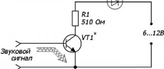
- Connect pin 3 of the Arduino to the base of the transistor via a 1k ohm resistor.
- Apply 12V to the collector of the transistor.
- Connect the positive lead of the 12-volt buzzer to the emitter and the negative lead to the ground bus.
- Connect pin 4 to pin 5V via a button. For safety reasons, in order to avoid large current flow, it is always better to do this through an additional small resistor.
- Connect the Arduino board to your computer via a USB cable and load the program into the microcontroller using the Arduino IDE.
- Power the Arduino board using a power supply, battery, or USB cable/
Usage
- After assembly and firmware, the device requires loading the configuration (using the utility).
- When connected to USB, normal operation of the device is suspended and the queue of unsent messages is cleared.
- If SMS sending fails, the device will try again after 2 minutes, then after 5, 10, 20, twice after 40 and then every 12 hours.
- Once a call is received, it will be completed in 3 minutes.
- The audible alarm sounds for 30 seconds.
- The events “door opening”, “movement” and “lighting changes” are triggered no more often than once every 20 minutes.
- If the device is not powered for more than 3 hours, the recorded temperature measurement history is reset.
Circuit operation
The device diagram is shown in the following figure.
In the diagram you can see that the trigger pin of the ultrasonic sensor is connected to pin 12 of the Arduino board, and the echo pin of the sensor is connected to pin 11 of the Arduino board. The Vcc pin of the sensor is connected to the 5V pin of the Arduino and the GND pin of the sensor is connected to the GND pin of the Arduino. One pin of the buzzer is connected to the GND pin of the Arduino and its other pin is connected to pin 8 of the Arduino board.
The operating principle of the device we are considering is very simple - when someone comes within the range of the ultrasonic sensor, the Arduino board calculates the distance to that object and if the measured distance is within a certain range, the Arduino transmits a high level signal to the buzzer and the buzzer starts sounding an alarm. The block diagram of the project is presented in the following figure.
You can check the operation of the circuit by placing an object in front of the ultrasonic sensor; all these processes can be seen in more detail in the video at the end of the article.
Field tests
I apologize for the editing aesthetics.
Installation on the front door. The part of the structure on the right (directly on the door itself) is a magnet for triggering the reed switch
The device was installed at a place of permanent use (garage) 4 months ago. For enhanced testing purposes, the schedule function is not used (an SMS is sent for each event). On average, there are 5 SMS per day: two when entering the garage (the door opening sensor and light sensor are triggered), two when leaving and one “daily report”. Currently the batteries (3x AA) maintain a voltage of 4.1V when the modem is turned on.
Code
const int buzzer=3; // pin 3 is the output to the buzzer const int pushbutton=4; // pin 4 is the input for the button void setup() { pinMode(buzzer,OUTPUT); // set pin 3 to output pinMode(pushbutton,INPUT); // set pin 4 to input } void loop() { // read the output of both sensors and compare the result with the threshold value int sensor1_value = analogRead(A0); int sensor2_value = analogRead(A1); if (sensor1_value > 400 || sensor2_value > 400) { while(true) { digitalWrite(buzzer,HIGH); // enable alarm if(digitalRead(pushbutton) == HIGH) break; } } else { digitalWrite(buzzer,LOW); // turn off the alarm } }
Problems
During operation, the room temperature dropped from +10°C to -15°C and two problems were discovered.
- The PIR sensor used begins to give false alarms at low temperatures. At +5°C, use became completely impossible: the number of false alarms exceeded one per day. An attempt to replace the sensor with another one did not solve the problem, so now this sensor is temporarily disabled. It is not yet clear what to do with this.
- The temperature sensor built into the DS3231 at -10°C and below began to go crazy: it periodically produces random values, for example, “-84°C” or “+115°C”. Interestingly, the RTC works fine. At the moment it is not clear whether this is a problem specifically for my copy or not. I'm waiting for a second identical module to be checked; if the problem with it repeats, DS18B20 will be added to the device.
Otherwise the flight is normal.
What is an Arduino module?
Arduinos are implemented in the form of small boards that have their own microprocessor and memory. The board also contains a set of functional contacts to which you can connect various electrified devices, including sensors used for security systems.
The Arduino processor allows you to load a program written by the user yourself. By creating your own unique algorithm, you can provide optimal operating modes for security alarms for different objects and for different conditions of use and tasks to be solved.
Arduino GSM module
Advantages. Flaws
Pros of a homemade security system:
- Minimum cost of initial components compared to industrial options.
- Autonomous operation (only periodic recharging of the phone).
- Prompt response.
- Possibility to connect several subscriber numbers.
- Options for connecting touch sensors.
- Wireless installation.
Minuses:
- The system is easily blocked upon detection. Requires hidden installation.
- Local triggering.
- Suppression, signal modification.
The use of a do-it-yourself GSM system is justified when it is necessary to install a security device with minimal resources, and the significance of the object is not high. For a home, apartment, or office, it is best to use industrial security modifications that are more reliable, efficient, and functionally diverse.