Probably many of you watched concerts of different styles and it was impossible not to notice how the electric guitar plays, how the masters of this instrument perform stunning solo parts. Perhaps many would like to try to play something themselves, play with the sound of an electric guitar, pluck a few strings and feel the power of this instrument...
What is a pickup
What is a guitar pickup? In simple terms and briefly, these are metal cores with magnets placed inside an inductor.
Steel strings, changing their position above the metal cores, create magnetic vibrations. With the help of an inductor, these changes in the magnetic field are converted into weak electrical signals.
The leads of the inductor are connected to the sensitive input of the device for amplifying and processing audio signals. As a rule, this is a special input with a high signal gain, an example would be the microphone input of a personal computer sound card or other low-frequency signal processing device (20-20000 Hertz).
The microphone input has a high gain and is excellent for these purposes; we will use it in the experiment.
Note:
Phase/antiphase switching is also used in tone block mods through Push-Pull potentiometers and toggle switches. Although you can wire it to normal volume, although this is a dubious idea.
These are all the options for connecting a humbucker. Some of them most likely will not be useful to you. The same Jimmy Page took his modified Les Paul to live performances, and there it helped him a lot, but when recording, you can achieve the desired sound with equalizers and post-processing. It is also worth remembering that frequent re-soldering of the guitar can have a bad effect on the potentiometers, and it is highly advisable to remember the standard humbucker connection.
Carcass for pickup
First we need to make a frame for the future guitar pickup. Below is a drawing of such a frame:
Rice. 1. Drawing of the frame design for a homemade guitar pickup.
As can be seen from the drawing, two plates are attached to the base with six holes at the top and bottom, thus forming a shuttle for winding the inductor wire.
Now I’ll tell you step by step how you can make such a pickup for a guitar, everything was done in haste, so it didn’t turn out very neatly, but it was quite functional - I was pleased with the end result.
Let's start production
First, the frame was made of wood, the upper and lower plates were cut from double-sided thin foil fiberglass. It is advisable to take a tree that is hard and dense; ash and beech are good choices. Instead of wood, you can use other materials without magnetic properties - plastics, plastic, etc.
Rice. 2. Wooden guitar pickup frame.
Rice. 3. Wooden guitar pickup frame with fiberglass plates.
Why plates made of foil fiberglass? - later, the contact with the foil for each of the plates will be connected to the ground (common wire), thus forming an additional screen and protection from interference and interference.
I did not round the corners of the fiberglass plates; later this area will be useful for mounting in the resonating hole of an acoustic guitar.
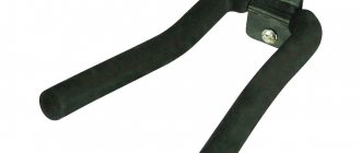
Next, it was necessary to find material for the cores - steel rods with a diameter of about 4 mm. For this purpose, a steel guide from an old dot matrix printer was used; it has a slightly large diameter - 5mm, but nevertheless it is an excellent material for cores.
Rice. 4. Steel guide from an old dot matrix printer.
Having prepared all the materials and knowing the diameter of the cores (5mm), you can drill six holes in the base, and then in the side plates of the future frame.
Using a ruler and pencil, six holes were marked, as shown in the drawing in Figure 1. To make sure that everything is correct, the base of the frame was immersed under the strings of the guitar, in this position you can check whether the axes of the intended holes correspond to the axes of the strings - I had to make a little adjustment.
For convenience and safety of drilling, the wooden base was wrapped twice in thin cardboard and then clamped in a vice.
You need to clamp it carefully, with little force, the main thing is to hold it firmly. We drill holes slowly, with a very sharp new drill and at high speed. With the use of a hand drill, this turned out to be not an easy task...
Rice. 5. Drilling holes in the wooden base of the pickup frame.
After drilling several holes with a hand drill, it became clear that things were bad. It was impossible to get the holes clearly in the center. A drilling machine would work well here, but I didn’t have such a unit.
It was decided to abandon the use of wood; a material with a higher density and, again, without magnetic properties was needed - a piece of organic glass was found.
With plexiglass we managed to drill all the holes more or less accurately the first time.
Rice. 6. Drilling holes in the base of the plexiglass pickup frame.
The result was this frame-base for the future pickup:
Rice. 7. Ready frame-base for the future pickup.
The base of the frame was attached to one of the fiberglass plates, using an awl to mark where the two outer holes on the plate needed to be drilled. We do the same with the second plate and drill the intended holes in them.
It's time to make the cores. As previously written, for the cores I used guides from an old dot matrix printer with a diameter of 5mm.
It is necessary to cut off six cores of equal height - for this we take the height of the plexiglass base of 10 mm and add about 4 mm to it (the thickness of two PCB plates + reserve), as a result it turns out that we need cores with a height of about 14 mm (the excess can then be filed off with a file and accurately fit).
After the cores are ready, we take two of them and insert them into the outer holes of the base, place one of the plates on the cores, and drill all the other holes in the fiberglass plate using the holes in the plexiglass. After this, we place the second plate on the other side and also drill holes in it.
This is what happened as a result of the work:
Rice. 8. Frame blank with drilled holes.
The edges of each of the plates, along the entire perimeter, need to be sanded a little so that they are not sharp and, when subsequently laying the wire on the reel, do not damage the enamel on it.
Rice. 9. Pickup frame with cores assembled.
To securely fasten the frame, I decided to screw the plates to the base using small self-tapping screws, the kind that can often be found in small-sized Chinese-made toys.
First, I drilled holes in the plates and the plexiglass base, using a drill slightly smaller in diameter than the diameter of the screws.
Rice. 10. Fastening the plates to the base using self-tapping screws.
The frame of the future acoustic guitar pickup is ready:
Rice. 11. Frame for a homemade pickup assembly.
X2DOUBLE G0 pickup. We turn the guitar into a transacoustic one with our own hands.
When I first saw and heard the Yamaha acoustic guitar of the “TransAcoustic” series, I was surprised by its sound and the effects that the guitar produced when not connected to the amplification path. I started to figure out what it was and how it worked, and in the vastness of AliExpress I came across a ready-made solution that allows you to turn any ordinary acoustic guitar into a transacoustic guitar with your own hands without radically altering it, which I want to share in the review below. In addition, at the end of the review, I’ll tell you about the problem that arose during the testing of the device and its solution, and I’ll also show a video with examples of the sound of a guitar with a pickup installed. I already mentioned the X2DOUBLE G0 pickup installed on my guitar in my review of the Doff D022 guitar: that’s why I decided to continue. On the Internet, I came across companies selling guitars and equipment that are ready to sell both a set of such a pickup for installation and install it on your instrument, although this pickup will have an additional Enya inscription, and the cost without installation will be about 10 thousand. rubles Apparently, Enya is a customer of X2DOUBLE and installs their pickups on his instruments.
I think it’s worth explaining here what a transacoustic guitar is. Such a guitar, in addition to reproducing the usual sound, allows you to get sound with chorus, delay and reverb effects without connecting to combo amplifiers and other separate devices. The signal that the pickup picks up from the strings of the guitar is processed inside the device itself by one effect or another, amplified and reproduced through a vibration speaker glued to the back of the guitar. Thus, the effect-processed sound comes from the body of the guitar itself, which at first seems very unusual.
This pickup was ordered at the 11/11 sale, plus a coupon was applied, and in the end the cost was a little more than 6 thousand rubles.
The package took a little over a month to reach me. The box was wrapped in bubble wrap and in a regular gray postal bag.
Inside there was an attractive box, and as a gift the seller added a guitar pick and a Sagitar branded napkin.
Inside the box were instructions and a kit for installing the pickup on the guitar: the pickup itself, a cable with connectors for connecting to sound amplification equipment, a microUSB cable for charging (yes, yes! Now an acoustic guitar can be charged!)))), a vibration speaker and a mounting kit .
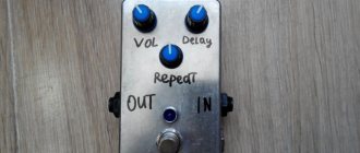
On the front panel there is a button for turning on the “Trans” effects, a button for switching the phase of the signal from the microphone “Phase” - it works when the pickup is connected with a cable and helps reduce self-excitation of the instrument, a “MicroUSB” charging connector, a device operation indicator that glows red when the battery is low and when charging and green during normal operation, three tone controls “Bass”, “Middle”, “Treble” and two “Mic Tone” controls – adjusting the frequency of the signal captured by the built-in microphone and “Trans Level” – adjusting the level of the mixed signal with effects. A small Phillips screwdriver is included to turn these adjusters.
On one side there is a regulator for the overall sound level “Volume” and “Mic” that regulates the level of the mixed signal captured by the microphone. On the other side there is a level control for the reverberation effect “Reverb” and one control for two effects “Chorus/Delay”. The first half of the turn of this knob changes the depth of the Chorus effect, and in the second half of the turn the frequency of the Delay effect is turned on and adjusted. On the reverse side there are two sockets for connecting a vibration speaker and a cable for connecting to sound-reproducing equipment, a battery in 18650 format and a microphone
More details about the battery:
Completely discharged, when charging in the device, judging by the testimony of the “white doctor”, it consumed a current of 0.46A and absorbed 2806 mAh
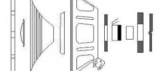
By removing two screws, the device is disassembled into 2 parts. At the top there is a pickup coil with magnets, at the bottom all the electronics for signal processing.
Let's see what's inside:
Made carefully, it is clear that the execution is factory, and not on the knee.
A vibration speaker with a branded sticker, but I think it’s no different from those that are sold in bulk on Ali. Glued with 3M tape
The connector for connecting the cable is made of high quality, but I didn’t like the blue color; it looks alien against the wood of the guitar. To install on the guitar you will need a drill or cutter with a diameter of 12mm:
As an experiment, I decided to install a pickup on my old Cremona D-670 dreadnought.
And later, when I got a Doff D-022 guitar, I reinstalled it on it.
So we take the guitar, remove the strings from it (you don’t have to remove them completely, secure them to the neck with a capo or tape, loosen them and remove them from the back stand and carefully fasten them to the neck so that they don’t get in the way), remove the strap holder from it and drill a hole first with a 4mm drill -6mm, and after 12mm. When drilling, do not press hard so as not to crack the lower ring. Although I think it is difficult to create such conditions for it to split.
We insert any cable with a large jack at the end into the resulting hole and pull it out through the hole in the resonator. Next, insert the Jack into the connector to be installed and pull the connector into the hole
You can do without a cable with Jack by simply passing a piece of wire and taping it to the connector with electrical tape, but it is unlikely that you will be able to do without this at all, because My hand with the connector inserted into the resonator hole did not reach the drilled hole from the inside. Next, we put on the washer and tighten the fastening nut, while the connector can be fixed with something thin, including the supplied screwdriver, so that it does not turn.
By positioning the nuts on the connector, you can adjust the length of its threaded part to the thickness of the guitar's claw.
Next, screw on the cap:
But I didn’t like the supplied blue one and replaced it with chrome, which I had from a similar connector
Next, we figure out how the wires from the connector and vibration speaker will pass to the pickup and glue the standard wire clamps inside the guitar:
They are also glued to standard 3M tape.
I already had a Fishman pickup kit installed on my Cremona, so I used a previously installed mount for the wires from it.
We glue the vibration speaker onto the back deck, in accordance with the diagram class=”aligncenter” width=”800″ height=”534″|fcw3qayjh5a| src=”https://pic.mysku-st.ru/uploads/pictures/06/67/96/2020/02/07/5f53e9.jpg” class=”aligncenter” width=”800″ height=”534″ [/img]
We thread the wires into the clamps
Connecting the wires to the device
Install the device into the hole of the guitar and tighten the screws.
Ready! And then I pull the strings on the guitar and... I hear extra sounds when the pickup is working. Moreover, this problem with overtones arose only when the pickup was working without a connection. When connected with a cable to a combo amplifier, everything sounded as it should, without distortion. Therefore, I concluded that the problem was in the output path, which amplified and transmitted the signal to the vibration speaker.
I made a video with the problem, attached it to a dispute on Ali with partial compensation for the cost of the goods, but Ali’s support solution was to return the goods to the seller and a full refund. But this option did not suit me, because... Shipping costs money, plus a loss of time, and you can buy it later at the same price as you bought it on 11.11. It wouldn’t have worked with a coupon, so I put Ali’s decision on the brakes, the dispute was automatically closed, and I kept the pickup. After thinking about what the problem might be, I decided to experiment. In the process, I found out that distortion begins to disappear when a certain distance is formed between the upper part of the pickup with a coil and magnets and the main block with the signal processing and amplification circuit. Most likely, the electromagnetic field created by the coil when receiving a signal from the strings influenced the amplifier path. At first I wanted to shield the part with the coil, by analogy with how they do it with single coils in electric guitars to reduce the background, but then I settled on a solution of making 4mm spacers from plastic, after installing which the distance between the parts of the pickup increased, which completely suited me - overtones and the distortion completely disappeared.
I already wrote above that after I got my Doff D022 guitar, this kit was reinstalled on it. But this guitar not only has a smaller body, but also a smaller sound hole, so I had to tinker with the installation, because... the body fits tightly there, and turning the adjuster wheels is not so convenient, but possible. In fact, the minimum diameter of the resonator hole of a guitar on which such a pickup can be installed can be considered 85mm
On Cremona the diameter is 12 mm larger and is 97 mm.
Well, at the end I’m attaching a video in which I tried to demonstrate how the effects work and the sound of the guitar with them. The guitar in the video sounds live, without connecting to any devices.
When you connect the guitar to sound-reproducing equipment, all effects retain their effect, but the ability to mix in the signal captured by the built-in microphone is also added, which also affects the reproduced sound.
That's probably all! I am ready to answer any questions you may have in the comments below.
Magnets for pickup
The next important part of a homemade pickup is MAGNETS. We need powerful magnets of small height, at first I thought of using magnets from old Soviet latches for furniture, but they are quite large in height and I had to go to the store.
A solution was found very quickly - neodymium magnets from old hard drives (hard drives), they are very strong and small-sized, quite a good solution!
Rice. 12. Neodymium magnets from old hard drives for the pickup.
Knowles SPW2430HR5H-B
Many different ideas have been proposed to increase the acoustic power of a piezodynamic or ultrasonic transducer. Most of them are based on rather complex circuits that increase the overall cost of the solution; for example, raising a low logic supply voltage to a higher voltage or using an H-bridge.
In contrast, this paper shows how the acoustic power of a piezoelectric transducer can be increased while minimizing the number of parts and cost. Before we begin discussing the new approach, let's look at some of the most commonly used piezoacoustic circuits and their disadvantages.
The simplest piezoelectric element driver circuit consists of a converter and a key transistor (Figure 1). The voltage on the converter cannot be greater than the voltage of the power supply, which determines the upper limit of the acoustic power. Resistor R2 serves to discharge the converter capacitance. The RC time constant must be short relative to the period of the resonant frequency of the converter. Low resistor values reduce electrical efficiency while damping the mechanical (acoustic) resonance of the transducer, which, of course, reduces acoustic efficiency.
Picture 1.Although this piezo emitter control scheme is simple, it is very inefficient.
The most common improvement is to replace R2 with a throttle, as shown in Figure 2.
| Figure 2. | Replacing resistor R2 with a choke increases acoustic power and efficiency. | |
The inductance value is often chosen to obtain electrical resonance with the capacitance of the transducer (emitter) at the acoustic resonance of the transducer. This approach can provide higher acoustic power than a parallel resistor, but it still leaves plenty of room for improvement. In the best case, the peak voltage across the converter can be as high as 40V, while the more typical value for a 5V supply is 20V.
This is because the collector-base junction of the transistor is forward biased during the negative half-voltage wave on the parallel resonant circuit formed by the inductance and capacitance of the transducer, which limits the voltage swing, reducing the acoustic output.
| Figure 3. | Using a diode can eliminate negative surges. | |
Adding a diode isolates the collector-emitter junction (or, if a MOSFET is used, the parasitic diode junction) from this negative half-wave, providing a much larger voltage swing across the converter and increasing acoustic power (Figure 3). Although the diode's forward voltage reduces the applied supply voltage, the increased voltage at resonance more than compensates for this small loss.
To make any further improvements, we must consider that there are actually two resonances in this small system:
- Acoustic resonance of the transducer, mechanical and volumetric resonances.
- Electrical resonance of the inductance and capacitance of the converter.
The electrical resonance frequency does not have to coincide with the acoustic resonance frequency. In fact, if it is approximately 2 times greater than the acoustic resonance frequency, the peak voltage at the transducer can be significantly increased.
| Figure 4. | Illustration of the behavior of the circuit in real conditions. | |
This is illustrated in Figure 4, where the waveforms were obtained with the following circuit parameters:
- Power supply voltage: 5 V DC;
- Inductance: L1 – 3.2 mH;
- Piezo transducer capacity: 2 nF;
- The frequency of the signal source (40 kHz) is equal to the resonant frequency of the emitter;
- The duty cycle of the signal source pulses is selected so as to eliminate large current surges when turned on.
Note that point 5 indicates a potential problem lurking in this new solution that needs to be addressed. If the signal source is able to turn on the transistor after the converter voltage becomes positive, there will be a large short burst of current that can reduce electrical efficiency and potentially destroy the transistor over time. Increasing the duty cycle so that the transistor turns on when the resonant voltage is slightly negative eliminates this overshoot.
Now that we've covered everything, let's see how our circuit performs in real life using a handy four-channel smart oscilloscope:
- Yellow – control voltage with a peak value of 5 V, a frequency of 40 kHz and a duty cycle of approximately 48%;
- Violet – voltage on the converter at electrical resonance: 92 V peak-to-peak, 80 kHz;
- Green – transistor emitter current with a peak level of approximately 80 mA and a frequency of 40 kHz;
- Blue – acoustic power of the transducer, measured with a MEMS microphone.
The high peak voltage at the converter is achieved by using an inductor with an inductance lower than that required for resonance at 40 kHz, allowing the current to rise approximately twice as fast. In the example under consideration, this provides double the current to “charge” the magnetic field of the inductor.
In this system, this leads to greater displacement of the transducer surface, and, accordingly, increases the acoustic power.
This article should not be considered a comprehensive treatise on resonant circuits. It simply demonstrates a procedure for increasing the acoustic power of any resonant piezoelectric transducer or emitter using a very simple and inexpensive circuit.
Briefly this procedure can be summarized as follows:
- We determine the acoustic resonance frequency of the transducer;
- We form a sequence of control pulses of the same frequency, starting with a duty cycle of 50%;
- If necessary, we adjust the duty cycle to eliminate current surges when turned on;
- We determine the value of the converter capacitance;
- We choose a value of inductance with which the frequency of electrical resonance will be approximately twice as high as the frequency of acoustic resonance.
It can be difficult to model the acoustic/electrical circuit presented here in a simulator because the transducer contains two or more potentially resonant elements. These include the mechanical resonance of the transducer element, the acoustic resonance of the transducer body (called Helmholtz resonance) and, of course, the electrical resonance of the transducer capacitance with the external inductance.
Acoustic loading by radiation from the transducer port or its diaphragm adds another complexity to the modeling. A simple electrical simulation of this circuit results in 240 Vpp-p at the converter, which is more than twice the voltage obtained in the actual circuit. Most of the losses that reduce the peak voltage of the converter in this system compared to the simulated results may be due to acoustic loading.
Using this simple procedure, you can easily achieve maximum acoustic output from the transducer with minimal time and effort.
Coil winding
Once the magnets have been found, you can confidently proceed to winding the inductor for the future pickup. It is advisable to wind approximately 2000-3000 turns of thin enameled copper wire with a diameter of 0.08-0.1 mm.
I decided to wind the coil until it was filled with wire with a diameter of 0.15 mm - it is convenient for winding and reduces the likelihood of breaking the wire during the winding process.
When wound with thin wire with a diameter of 0.08-0.1 mm, the quality of the pickup will most likely be better and will accommodate 2-3 thousand turns.
The wire can be found at the bazaar or ordered from an online store. As a last resort, you can unwind it from some kind of transformer or coil from an electromagnetic relay.
Rice. 13. Coil with wire for winding the coil of the future pickup.
We clean the beginning of the wire from the enamel and tin it using a soldering iron. We cut off a piece of insulated conductor 12-15 cm long, remove about 5 mm of insulation from one of its ends and tin it with a soldering iron.
We screw the beginning of the enameled copper wire to the tip of the conductor and solder them. We cut a strip of insulating tape and isolate the soldering area.
Rice. 14. We begin winding the pickup coil.
We place the insulated end of the wire into our frame and wrap it with several dozen turns for reliable fixation. Now you can safely wind the rest of the coil without fear that the wire will crawl out or go to the side.
Here is an example of fixation (the magnets are not yet fixed, they are simply held due to the force of attraction to the cores):
Rice. 15. Fixing the beginning of the coil in the pickup frame.
After an hour or two of winding (a slightly tedious process), the pickup inductor was filled to capacity with wire.
Rice. 16. The pickup coil is ready.
We tin the end of the coil conductor with a soldering iron and solder it to the second insulated conductor. Use electrical tape to insulate the connection. Using a thread, we wind the insulated junction of the conductors to the coil to securely fix it.
Note #2:
Carefully check that the North Finish and South Finish are securely connected to each other and are isolated from the rest of the circuit. A broken wire and a poor connection in this exact place have more than once been the cause of poor performance of guitars that I have soldered.
A very popular modification of humbuckers. Cut-off - turning off one sensor coil from the circuit so that the other starts working as a single. As a rule, toggle switches and push-pull potentiometers are used for this, so that it is possible to switch to the cutoff mode and back.
Of course, the beginning and end of the northern coil is North, and the southern coil is South. You can solder them like regular singles. (A link to wiring diagrams is given at the beginning of the page).
Let me remind you that you can read about how to make a cutoff via push/pull here:
- Push/Pull cutoff in a nutshell
Parallel connection is a scheme in which we do not get a humbucker, but two single coils operating simultaneously and located next to each other, on the same base. In this case, the properties of the humbucker itself are lost, but some people like this sound. Here is the diagram (picture clickable):
This is really not for everybody. But among these fans there were some very respected people, for example Jimmy Page. =)
Also, one of the striking examples of such a sound is the clean guitar part in the Metallica song - To Live Is To Die.
You can also reverse the phase when connected in parallel. For those gentlemen who know a lot about perversions.
Shielding the pickup
The next very important and “tasty” stage is shielding the pickup coil. The screen is needed to protect the coil from interference and interference. Without a screen, there is a chance that instead of the sound of a guitar you will hear some kind of radio, to which you will act as an antenna. ))
We will shield the coil using foil removed from the chocolate bar (it’s not for nothing that I said that the stage is “delicious”). After you have savored the chocolate and rested after a long winding of the reel, you can get down to business.
Cut a strip of foil large enough to wrap around the pickup coil. You can take several strips, the main thing is to completely hide the coil under the foil.
Rice. 17. The chocolate was delicious, and we will need the foil.
IMPORTANT: when shielding, you should not get a closed turn around the coil - the foil strip should not close into a ring, otherwise you will get an additional single-turn coil from the screen, which will interfere with the normal operation of the pickup!
In the place where the foil ring closes after laying, you need to insulate the ends of the strip from each other using a dielectric. Simply put, make sure that the ends of this annular screen do not short-circuit with each other. You can use electrical tape, tape, thin film, etc. as insulation.
You also need to make a connection to the screen - take a piece of insulated wire and attach its stripped end of insulation to the foil, and then secure it all with tape or tape.
The connection is best made at a point that is evenly spaced from the ends of the foil, which are isolated from each other and do not close together.
__________________ connect / \ here ———>| \_________________/
To prevent the resulting screen from spreading and to hold securely, you can wrap it on top with electrical tape or thread.
In my case, the situation is slightly different: since the side plates are made of foil fiberglass, the foil has contact with the copper surfaces of the two plates (top and bottom). In this case, the foil coil can be closed, since the result is a “closed container” (a parallelepiped from the screen).
Rice. 18. The pickup coil is in a screen made of foil and side copper walls of fiberglass, shielded on all sides.
As a result, we have an almost finished pickup with three conductors coming out of the structure: two from the coil, and one more from the screen.
Rice. 19. The pickup with a coil shielded on all sides is almost ready.
The last thing to do is attach the magnets to the bottom of the pickup. The fastening must be done so that each core is in contact with the magnet; later the magnets can be fixed with fusible silicone or simply wrapped with thread.
Rice. 20. Ready-made homemade acoustic guitar pickup.
The pickup is actually ready for testing and operation!
How to make a pickup for an electric guitar?
A true musician values his instrument and takes care of it. The best accessories are selected for the guitar. But if there is not enough financial resources for the best, then you have to get out. You can make a device such as a sound pickup yourself.
Required tools and materials
How to make a pickup for an electric guitar at home with your own hands - we will study in this article. To get started you will need the following:
- Choosing pickups for an electric guitar to suit the style of music
- Material for the frame. It can be wood, plastic, plexiglass.
- Bolts of the required size.
- Varnished wire with a diameter of 0.2 millimeters.
- Magnet.
To fasten parts you can use Moment glue.
Step-by-step instruction
After preparing the materials, the stage of manufacturing the ideal sound device begins. Step-by-step instruction:
- The main stage is the manufacture of a housing for winding wire. 4 internal plates and two external ones are cut from durable material. Each internal plate is 60 millimeters long and 6 millimeters high, while the outer plate is 65 millimeters and 16 millimeters, respectively. All parts are glued together. After gluing, the thickness of the internal plates is 10 millimeters. After the glue has completely dried, holes with a diameter of 4.6 millimeters are drilled in the body at a distance of 10 millimeters from each other. Bolts are inserted into the holes.
- The second step is winding the wire. It must be wound tightly - at least 2000 turns. For store-bought pickups, the number of turns can reach 8000. One end of the wire is brought out to remove the contact. When winding, do not rush. The winding must be intact, without breaks. If the wire breaks, you have to go back to the beginning. It is advisable to wrap the finished coil in brass. This is done to remove noise and reduce background. Wiring needs to be soldered to the coil.
- Then the magnet is installed. Attached to the bottom of the reel with glue.
After the glue has completely dried, the device is ready. You can install it on a musical instrument and try it out.
Connecting a pickup
To connect the pickup to the microphone input of the computer, I used a 3.5 mini-jack plug (as in standard headphones from a player).
A thin shielded coaxial cable was used as a connecting cable (a 2-meter piece was lying around somewhere, so I used it), it is advisable, of course, to buy a shielded microphone cable, but for experimental purposes, this option will do. )
Here is the diagram according to which the pickup was connected:
Rice. 21. A simple experimental circuit for switching on a homemade pickup.
To adjust the volume, the pickup can be connected through a variable resistor, but this will most likely be superfluous here; such a circuit turned out to be quite workable, and the volume can be adjusted without problems in a computer mixer.
Well, that’s all, such a pickup is quite suitable for trying out what an electric guitar is, and for playing complex compositions and fast solos you can’t do without a full-fledged electric guitar with sensitive and high-quality pickups.
The pickup was secured to the resonator hole of the acoustic guitar using electrical tape and pieces of rubber. Rubber pads are needed to raise the pickup a little higher to the strings, so that when the strings are clamped they do not touch the pickup cores, and also to avoid scratching the varnished surface of the guitar body.
This way I didn't have to drill or cut anything into the body of the guitar. You can remove the pickup at any time without leaving any trace of its presence on the guitar.
Rice. 22. Homemade acoustic guitar pickup.
Rice. 23. Homemade acoustic guitar pickup, angled view.
Rice. 23. Homemade acoustic guitar pickup, general view.
How to install a pickup on an electric guitar?
To replace the device on an electric guitar, you need to do the following:
- Remove the strings.
- Turn the instrument over and remove the cover. To do this, the bolts are unscrewed, and the cover is removed using adhesive tape - glued to the cover and pulled.
- A marker marks the connection points of the device.
- A soldering iron is used to unsolder the wires from the connection points.
- The cable of the installed device is wrapped around copper wire.
- The wire is pushed through the wire into the electronics compartment.
- The copper wire is removed.
- The device is secured in place using screws.
- All wires are soldered in place.
- The operation of the device is checked. The instrument is connected to a power source and light taps are made on the device. A clear sound should be heard.
Finally, the lid is screwed on and the strings are tightened.
In conclusion
You can come up with a good mount for the pickup and make everything better. But my goal was simple - to play around and try, to make it quickly and so that it would function, the goal was achieved 100%. The pickup turned out to be quite sensitive, and there was no obvious interference or background.
I feed the signal from the guitar to the microphone input of the computer’s sound card, and then run it through the Guitar Rig 4 program to obtain various combinations of effects - from simple amplification and echo to deep Distortion. ))
I wish you all creative and musical success!