Gears are found in many mechanisms today. And not only big and powerful ones. For example, plastic gears are found in many household appliances. What to do when they fail?
Indeed, making them is not such a big problem. It will be much more difficult to turn gears out of metal. Moreover, if the gear bears a large load. To quickly produce a shaft or gear, in this case professionals who have specialized industrial equipment will help.
Running method
The rolling method is the most common option for manufacturing gears, since this method is the most technologically advanced. In this manufacturing method, the following tools are used: cutter, hob cutter, comb.
Rolling method using a cutter
For the manufacture of gears, a gear shaping machine with a special cutter is used (a gear equipped with cutting edges). The procedure for manufacturing gears takes place in several stages, since it is not possible to cut off the entire excess layer of metal at one time. When processing a workpiece, the cutter performs a reciprocating movement and after each double stroke, the workpiece and the cutter rotate one step, as if “rolling” over each other. When the gear blank makes a full revolution, the cutter performs a feed motion towards the workpiece. This production cycle is carried out until all the required metal layer has been removed.
Rolling method using a comb
A comb is a cutting tool, its shape is similar to a rack, but one side of the comb teeth is sharpened. The blank of the gear being manufactured produces a rotational movement around its axis. And the comb performs a translational movement perpendicular to the axis of the gear and a reciprocating movement parallel to the axis of the wheel (gear). Thus, the comb removes the excess layer across the entire width of the gear rim. Another option for the movement of the cutting tool and the gear blank relative to each other is possible, for example, the workpiece performs a complex intermittent movement, coordinated with the movement of the comb, as if the profile of the cut teeth is engaging with the contour of the cutting tool.
This method allows you to produce a gear using a hob cutter. The cutting tool in this method is a hob cutter, which, together with the gear blank, produces a worm gear.
One gear cavity is cut with a disk or finger cutter. The cutting part of the cutter, made in the shape of this cavity, cuts the gear. And with the assistance of the dividing device, the gear being cut is rotated by one angular step and the cutting process is repeated. This method of manufacturing gears was used at the beginning of the twentieth century, it is not accurate, the cavities of the produced gear are different, not identical.
Alloy selection and production on a rotary table
Initially, you need to do a little calculation. It is necessary to calculate by what amount the part will need to be rotated in order to grind the required number of teeth equally spaced from each other.
This is very simple to do - you need to divide the total length of the turntable by the number of teeth. It is convenient to write down the movements for each tooth in a separate note. Now all that remains is to securely secure the workpiece and perform cutting.
Naturally, if you make a gear out of metal, then only one that will be practically eternal. This implies the use of a durable alloy. It is recommended to use d16t duralumin.
Even under significant loads, this alloy performs well. The main thing is that after installing the gear in the mechanism, lubricate it and change it regularly. In this case, the resource of the gear will be simply cosmic.
Not everyone has a turntable and a special mandrel for it in their garage. The production of gears by professionals will be the best option (it will save a lot of time).
Subtleties of tooth modeling. Optimal number of teeth
Think about it: if you want a 2:1 gear ratio for a linear mechanism, how many teeth should there be on each gear? Which is better - 30 and 60, 15 and 30 or 8 and 17?
Each of these ratios will give the same result, but the set of gears in each case will be very different when printed.
More teeth give a higher friction coefficient (the number of teeth meshing at once) and provide smoother rotation. Increasing the number of teeth means that each of them must be smaller to fit the same diameter. Small teeth are more fragile and more difficult to print accurately.
On the other hand, reducing the number of teeth provides more volume for increased strength.
Printing small gears on a 3D printer is like painting fine lines in a coloring book with a thick brush. (This is 100% dependent on the nozzle diameter and the horizontal resolution of the printer. Vertical resolution does not play a role in the minimum size restrictions).
If you want to test your printer by printing small gears, you can use this STL:
The printer we tested performed everything at the highest level, but with a diameter of about half an inch, the teeth began to look somewhat suspicious.
The advice is to make the teeth as large as possible, while avoiding warnings from the program about having too few teeth, and also avoiding intersections.
There is one more thing to consider when choosing the number of prongs: prime numbers and factorization.
The numbers 15 and 30 are both divisible by 15, so with that many teeth on two gears, the same teeth will continually bump into each other, creating wear points.
A more correct solution is 15 and 31. (This is the answer to the question at the beginning of the section).
In this case, the proportion is not observed, but uniform wear of the pair of gears is ensured. Dust and dirt will be distributed evenly throughout the gear, as will wear.
Experience shows that it is best if the ratio of the number of teeth of the two gears is in the range of approximately 0.2 to 5. If a higher gear ratio is required, it is better to add an additional gear to the system, otherwise you may end up with a mechanical monster.
How many teeth are there?
Such information can be found in any Mechanic's Handbook. 13 is the minimum recommendation for gears with a pressure angle of 20 degrees, 9 is the recommended minimum for 25 degrees.
A smaller number of teeth is undesirable because they will intersect, which will weaken the teeth themselves, and the problem of overlap will have to be solved during the printing process.
How to replace epoxy glue
The good thing about the above method is that it has been tested many times and is considered reliable. However, cases often arise when there is no high-quality two-component glue at hand. What can replace it with and are there any analogues?
As one option, you can use ordinary epoxy resin mixed with a special hardener. It forms quickly and is characterized by excellent flexibility, which, with the proper skill, allows you to exactly replicate the original teeth of a broken gear.
Epoxy resin for creativity
To enhance the effect, it is recommended to add dry cement in a 2:1 ratio to epoxy resin, carefully prepared exactly according to the instructions. By thoroughly stirring the mixture, you can obtain a composition so strong that it will help completely restore a broken plastic gear.
Now you know how to use two-component epoxy glue and its analogues to repair plastic parts. If you need help from people dealing with similar things, write about it in the comments. This way you can ask for valuable advice from those who have already repaired plastic gears and have experience in this field.
Special advantages of layer-by-layer printing and examples of the use of gears
So, what is the advantage of 3D printing gears over traditional gear manufacturing methods, and how strong are the gears?
Printed plastic gears are cheap, the process is fast, and you can easily get a customized result. Complex gears and 3D variations are printed without problems. The prototyping and creation process is fast and clean. The most important thing is that 3D printers are common enough that a set of STL files from the Internet can supply thousands of people.
Of course, printing gears with common plastics is a compromise in surface quality and wear resistance when compared to cast or machined plastic gears. But if designed correctly, printed gears can be quite an effective and reasonable option, and for some applications, ideal.
Most production applications look like a reducer
typically for small electric motors, handles and winding keys. This is because electric motors work great at high speeds, but they have problems with a sharp drop in speed, and it is problematic to do without a gear drive in this case. Here are examples:
Materials for work
Let's consider devices and materials that will be useful during the restoration of plastic parts. The main working tool is two-component glue. It is much more effective than superglue, has excellent adhesion and is universal in use.
Two-component adhesive should be used specifically for plastic parts. Otherwise, the composition may turn out to be too caustic and aggressive, which will inevitably lead to deformation of the plastic surface.
Among other equipment needed for work, you will need:
- degreaser - helps eliminate the oily film that reduces adhesion between gear parts;
- a small container in which you can place the gear for secure fixation;
- machine oil - it is recommended to use purified oil, but any other will do.
In addition, you will need available means with which you can mix the components of the solution to be prepared further and apply it to the surface of the gear. To do this, you can use small wood chips, toothpaste, or even a thick piece of cardboard. Work with what is most convenient.
Step 1. Degrease the surface
A key stage that requires a competent approach. Plastic gears often retain lubricant, which reduces friction between parts and prevents wear of the moving mechanism. Lubricant plays an important role in the design of the device, but does not allow broken parts to glue together, so it is necessary to remove it without leaving any residue.
When choosing a degreaser, make sure it has an optimal, non-aggressive composition. Caustic components often lead to “boiling” of the plastic: the surface bubbles, deforms, and deteriorates. Even ordinary acetone sometimes turns out to be very toxic and caustic.
You can eliminate fatty substances without any residue in the following way:
- fill the container with warm water;
- place the gear;
- add a fat dissolving agent;
- We wait for a while;
- brush the surface of the gear with the bristles of a toothbrush.
Even after the first procedure, you can notice that the surface has become cleaner and the characteristic slipperiness has disappeared. After drying the part, you can proceed to the next step.
Step 2. Prepare the glue
Two-part adhesive is the best choice for repairing plastic parts. To do this you need:
- squeeze the glue out of both tubes strictly according to the proportions indicated on the packaging;
- mix into a homogeneous paste using wood chips in some convenient container.
Some types of gears
External and internal spur gears, parallel helical (helical), double helical, rack and pinion, bevel, helical, flat top, worm
Spiral gear (herringbone).
It is commonly seen in printer extruders, they are complex to operate but have their advantages. They are good for their high coefficient of adhesion, self-centering and self-leveling. (Self-leveling is annoying because it affects the operation of the entire structure). This type of gear is also not easy to produce using conventional equipment such as hobby printers. 3D printing knows much simpler methods.
Worm gear.
Easy to model, there is a great temptation to use it. It should be noted that the gear ratio of such a system is equal to the number of gear teeth divided by the number of worm openings. (You need to look from the end of the worm and count the number of starting spirals. In most cases it turns out from 1 to 3).
Rack and pinion gear.
Converts rotational motion into linear motion and vice versa. Here we are not talking about rotation, but about the distance that the rack travels with each turn of the gear shaft. It is very simple to calculate the density of the teeth: you just need to multiply their density on the rack by pi and by the diameter of the gear. (Or multiply the number of teeth on the rack by the tooth density on the pinion).
Garden items
When answering the question of what can be made from wood, it is worth mentioning cool crafts for the garden plot, which are made extremely easily and quickly. If you make a sketch, it will not be difficult for even a school-age boy or girl to create them. The material used is usually ready-made planks or untreated wood. Here are some ideas, as well as step-by-step instructions for making them:
- Pots for bush-type plants. Many people have heard that ficus benjamina and other trees and shrubs can be grown in garden conditions, but not in open ground, since their root system does not tolerate large spaces. However, if the farm has a jigsaw with various attachments, then you can make a pot directly from hemp. You just need to cut out the core and you will get an original flowerpot for your favorite plant.
- Log box. Many gardeners have encountered a problem when there is simply no place to place gardening tools on their property. To fix this, just make a mini-box out of logs, connecting them together with slats on the inside. Wood is also nailed underneath. At first glance, such a box looks very expensive, but in fact its cost is no more than 200 rubles.
- Pots for the veranda. In the descriptions of some plants, many girls involved in gardening have probably seen more than once that crops can be grown in flowerpots - hanging pots. Such a product can be very easily made at home using a decimal board (10 mm). The product is attached to a regular nylon thread, which is threaded into holes prepared in advance using a drill.
And in various online master classes you can often see how a person makes transformable furniture from wood. For example, you can make benches that transform into a table or stool, inside of which there is an opening hole for storing valuables. At first glance, creating such products is incredibly difficult. Nothing like this! You just need to know how to use a jigsaw and install the canopies evenly, allowing the furniture to transform in the desired direction.
Method of making gears from plastic
As mentioned above, plastic gears are often used in household appliances, hand tools, etc. The following are the stages of their manufacture:
- in a graphic editor, a part (gear) is designed in the image and likeness;
- The file also records gear measurements (dimensions of individual parts);
- the file itself is sent to the nearest laser cutting machine (often this machine is owned by advertisers who use it to create souvenir products).
At the same time, plexiglass is used as a new material for production. You can be sure that the new gear will be much stronger, and the manufacturing accuracy will be excellent in any case (laser cutting cannot do otherwise).
As you can see, in the case of plastic everything is quite simple. And the cost of a single part (one gear) is unlikely to exceed $6. Of course, it may be a little expensive. But do not forget that we are talking about piece production.
For metal you will have to take a slightly different approach.
Methods for manufacturing gears and gears
For the manufacture of gears, the following materials are used: iron, cast iron, bronze, simple carbon steel, special steel compositions with an admixture of chromium, nickel, vanadium. In addition to metals, softening materials are used: leather, fiber, paper, they soften and reduce noise. But metal gears can also operate silently if their profile is made with precision.
: Formulas and calculations
Formulas for drawing and making gear teeth can be found in abundance on the Internet, but for a beginner they seem very complicated.
I decided to simplify the problem and the solution works very well on both large and small scales. On a small scale this is best suited for machine cutting with laser cutters, for example very small gears can be successfully produced this way.
How to make a gear according to a sample with your own hands
One of the most complex and yet widespread mechanical systems is the gear train.
It is a great way to transfer mechanical energy from one place to another and a way to increase or decrease power (torque) or increase or decrease the speed of something. How to make a gear with your own hands? The problem is always that creating effective gears requires quite a lot of drawing and math skills, as well as the ability to create complex parts.
For the hobbyist there is no need to have maximum efficiency, so we can get a much easier system to make, even with the tools at hand.
A gear is a series of teeth on a wheel. (Note in the diagram above, they labeled the wrong number of teeth on the gears - sorry)
Specific problems of layer-by-layer printing
- Printed gears usually require little post-processing before use. Be prepared for wormholes and the fact that the teeth will need to be processed with a blade. Reducing the diameter of the central hole is a very common problem even on expensive printers. This is the result of many factors. This is partly due to thermal compression of the cooling plastic, and partly because the holes are designed in the form of polygons with a large number of angles that contract around the perimeter of the hole. (Always export gear STL files with a large number of segments).
Slicers also contribute because some of these programs can choose different points to go around the holes. If the inner edge of the hole draws the inner edge of the extruded plastic, then the actual diameter of the hole will have a slight shrinkage, and it may take some force to insert something into this hole later. So the slicer may quite intentionally make the holes smaller.In addition, any discrepancy between the layers or the discrepancy in the width of the intended and actual extrusion can have a quite noticeable effect by “tightening” the hole. You can combat this, for example, by modeling holes with a diameter of approximately 0.005 cm larger. For similar reasons, and to ensure that the printed gears fit next to each other and can work, it is recommended to leave a gap of approximately 0.4 mm between the teeth in the model. This is a bit of a compromise, but the printed gears won't get stuck.
- Another common problem is getting a solid fill, which is quite difficult for small gears. Gaps between small teeth are quite common, even when the slicer is set to 100% infill. Some programs deal with this relatively successfully in automatic mode, but you can manually solve this problem by increasing the overlap of layers. This problem is well documented on RichRap, and there are various solutions to it in the blog.
How to make gears from plywood
Hello, dear readers and DIYers!
There are many mechanisms that use gears. Surely, you understand the importance of this detail, and you want to learn how to make such parts yourself.
In this article, Matthias, author of the YouTube channel “Matthias Wandel”, will tell you about a simple method for producing such gears from wood, more precisely from plywood.
The author has previously made similar gears; they are successfully used in various mechanisms and devices of his machines.
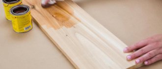
Materials needed for homemade work. — Sheet plywood — Bolts, washers, screws — Wood glue, acrylic varnish, sandpaper.
Tools used by the author. — Band saw, drill press — Three-point wood drills — Belt sander — Digital protractor — F-clamps, vice, printer — Screwdriver with bit set — Protractor, file, mallet, awl, scissors, pencil.
Manufacturing process. First you will need to create a paper template - a sketch of the future gears. You can create similar templates yourself by following the following link.
In this electronic online gear template generator you can select the desired size and configuration of gears for your projects.
The printed template is cut out and glued onto a plywood sheet. At the same time, the less glue you use, the better - after cutting out the part, the paper will have to be removed in any case. Not carpentry glue, but contact aerosol glue or a stationery glue stick are great for this.
The approximate shape of the wheel is then cut around the template using a band saw. The circle is made with a small margin for subsequent processing.
When the circle is ready, the centers of future holes are pricked around the circumference of the circle between each pair of teeth. A mark is also made in the center of the gear.
The resulting recesses are designed to guide the central tip of a three-point drill through wood with a diameter of 8 mm so that between each pair of teeth neat holes are obtained with the minimum possible displacements. To perform this operation you need to use a drilling machine or a drill with a special guide.
Next, the tape machine table is set at an angle of 5 degrees. This is necessary in order to give the gear teeth an appropriate bevel, thanks to which they can rotate much softer and smoother. This operation can be done using a protractor, a digital protractor, or a smartphone with the appropriate program.
Before cutting the teeth, it is advisable to place a sheet of plywood or a wooden panel under the workpiece and position it so that the saw blade is in contact with it. This way the author reduces the number of chips on the back side of the workpiece. This sheet is fixed on the table with a pair of clamps.
With the table tilted to the right, the author cuts out the left side of each tooth. In this case, the teeth will taper slightly towards the side.
Then the band saw table should be tilted in the opposite direction, to the left. However, as you know, most band saw models do not provide for tilting the table to the left.
Therefore, the master returns the table to its original, horizontal position. Then he places a wooden board of such thickness under the plywood lying on the table to create a plane inclined at approximately an angle of 5 degrees.
The plywood lining is again fixed with clamps at the edge and in the place where the board is placed.
Only after this the right side of each clove is cut out. Thanks to the holes previously drilled on the drill press, there is no need to align the teeth at their base.
Lastly, the teeth are equalized in length.
As you can see in the photo, thanks to the plywood, not a single chip appeared on the back side of the workpiece.
Before further processing, you need to drill a hole for the axle. In the author's case, this will be an M8 bolt.
Once the center hole is drilled, you can discard the paper template. The author did this on a belt sander, but you can get by with a wide chisel.
The author tests the finished gear on his own mechanism (replacing the previously manufactured one). In this case, no jams or jams were recorded. The wheel rotates smoothly.
If the gears get a little stuck, you can sharpen their teeth a little with a file. The photograph shows that the teeth taper somewhat towards the viewer. This effect was achieved by tilting the band saw table.
The next task of the master is to make the handle for this gear. To do this, he glues a small wooden block to the side of the gear. The handle will be attached to it using a bolt.
The finished product is coated with a layer of transparent varnish. The author pays special attention to the surfaces of the teeth. This will further strengthen the wood fibers of the teeth and slow down their wear.
For the handle itself, a piece of wooden dowel with a diameter of about 20 mm will do. A through hole for a screw is drilled in it and countersunk. The latter is selected with a smooth shank. The author shortens a long screw with a grinder, taking into account the length of the handle and the thickness of the gear with the lining.
You also need to remove the chamfer by restoring the threads on the end of the screw. This can be done on a sharpening machine or with a file.
Then, for the same screw, a hole is drilled in the wheel itself. The hole should be slightly smaller in diameter than the screw itself, since we need a fairly tight fit.
The self-tapping screw is not screwed in completely so that the handle can turn easily.
And here is the final test. The gear is securely fixed to the tool. Everything is working! Maybe a little loud, but it works.
I thank the author for a very simple method of making gears from plywood.
Good mood, good health, and interesting ideas to everyone!
Subscribe to the telegram channel
site so as not to miss new articles.
The author's video can be found here.
Source
Tags
Gears
Plywood products
Plywood is one of the most convenient materials, as it is easy to process. In addition, a sheet of plywood is much wider than any slats, so you can make a variety of products from it using a carpentry jigsaw. Here is just a small list of popular new products taken from YouTube that can be used to make cool wood crafts:
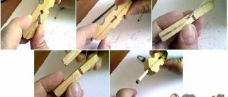
- rifled weapons of various calibers, which, although they do not fire shot, look very unusual;
- incredible wooden windmills created by gluing together only 10-15 parts;
- antique wooden carts that even a child can create;
- animals for the garden plot, cut from a piece of plywood.
How to choose?
Before buying oil, you need to study all the varieties, determine what it is needed for and make sure that it meets the following requirements:
- Inertness to polymers (the lubricant should not react with plastic so as not to harm moving parts; even universal mixtures can damage the plastic surface).
- Composition stability (lubricant for plastic gears should adhere well to the plastic surface and not change viscosity and thickness at low and high temperatures).
- Versatility (very often, driving mechanisms use elements not only of plastic, but also of metal and rubber, so the product must be suitable for different materials).
- Compatible with fluoroplastic (most plastic gear mechanisms are made from this material, so if there is no information about the material, this lubricant will almost certainly work).
- Non-flammable (plastic gearboxes get very hot, so the lubricant should not spontaneously ignite due to high temperature).
- Environmentally friendly (it must be safe for humans, since plastic friction pairs are often found in kitchen and other appliances with which humans come into direct contact).
- Resistance to moisture (it should protect the mechanism from water and not be washed off by it).
- Good adhesion (the plastic surface is very smooth, so ordinary oils do not adhere well to parts).
Differential setting
After installing the part and cutter on the machine, it is necessary to configure the transmission between the main and secondary spindle. Different machines do this in their own way:
a) changing the guitar's idle gears
b) shifting the gearbox
c) synchronization of electric drives with frequency control.
In machines with a gear guitar, the setting comes down to representing the ratio of the module to the gear ratio, which is individual for each machine model, as the ratio of the products of numbers indicating the number of teeth in the idler gears. In modern machines, synchronization of the gear with the cutter is performed automatically in accordance with the specified processing parameters.
Restoring a plastic gear
efesdev | April 24, 2012 | 59456
restoration of plastic gear
After the next maintenance, somehow the climate in the car started to work incorrectly. The air intake damper, which is responsible for recirculating air inside the car, did not completely cut off air from the street. The malfunction was not long in coming. A crashing sound began to be heard in the glove compartment area. At the station they said that the motor actuator (damper drive) had run out.
Namely, four teeth on the gears in the gearbox of this drive broke off. The asking price is $150 and replacement of the entire gearbox is complete. The reason is incorrect installation of the cabin filter. Leaves and other debris fell into the sump, preventing the valve from closing. The position sensor constantly turned on the engine. The search for people who can grind the gear was not successful; during disassembly they included such a price that it would be easier to buy a new gearbox. The idea came to make the entire gear by casting, but then I decided to make everything much simpler.
So we take paraffin and heat it up. We make an impression, then unfold the gear and make an impression of the missing teeth. We insert the gear and fill it with epoxy. It hardens, we process it with a file and you will be happy! Everything works without any issues. This idea was prompted by an article on a friendly website. This is how the man made the missing handles. Casted from epoxy, then painted in color.
Other articles in the section “Neizada Hands”,
Restoring a plastic gear
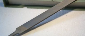
Restoration of teeth
We make such a peculiar tubercle.
We place the gear on an improvised stand so that the glue thickens even more. Again, everything is individual, I personally needed about 20 minutes for the consistency to noticeably thicken.
You can speed up the reaction and reduce the thickening time by heating. For example, take a hairdryer and start heating the glue on the gear.
Restoration of teeth
As a result, another gear will roll the track on the thick glue.
Now you understand that before rolling the teeth, the epoxy glue on the gear must cure to the consistency of hard plasticine. The lubrication will prevent the glue from sticking to another gear.